EP0192082B1 - Lead connector - Google Patents
Lead connector Download PDFInfo
- Publication number
- EP0192082B1 EP0192082B1 EP86100997A EP86100997A EP0192082B1 EP 0192082 B1 EP0192082 B1 EP 0192082B1 EP 86100997 A EP86100997 A EP 86100997A EP 86100997 A EP86100997 A EP 86100997A EP 0192082 B1 EP0192082 B1 EP 0192082B1
- Authority
- EP
- European Patent Office
- Prior art keywords
- connector
- contacts
- contact
- lead
- contact surfaces
- Prior art date
- Legal status (The legal status is an assumption and is not a legal conclusion. Google has not performed a legal analysis and makes no representation as to the accuracy of the status listed.)
- Expired
Links
- 239000004020 conductor Substances 0.000 claims description 13
- 230000008878 coupling Effects 0.000 claims 1
- 238000010168 coupling process Methods 0.000 claims 1
- 238000005859 coupling reaction Methods 0.000 claims 1
- 230000004936 stimulating effect Effects 0.000 description 8
- 230000000638 stimulation Effects 0.000 description 8
- 239000010963 304 stainless steel Substances 0.000 description 1
- 229910000589 SAE 304 stainless steel Inorganic materials 0.000 description 1
- 230000000712 assembly Effects 0.000 description 1
- 238000000429 assembly Methods 0.000 description 1
- 239000000560 biocompatible material Substances 0.000 description 1
- 229920002379 silicone rubber Polymers 0.000 description 1
- 239000004945 silicone rubber Substances 0.000 description 1
- 238000004088 simulation Methods 0.000 description 1
Images

Classifications
-
- H—ELECTRICITY
- H01—ELECTRIC ELEMENTS
- H01R—ELECTRICALLY-CONDUCTIVE CONNECTIONS; STRUCTURAL ASSOCIATIONS OF A PLURALITY OF MUTUALLY-INSULATED ELECTRICAL CONNECTING ELEMENTS; COUPLING DEVICES; CURRENT COLLECTORS
- H01R29/00—Coupling parts for selective co-operation with a counterpart in different ways to establish different circuits, e.g. for voltage selection, for series-parallel selection, programmable connectors
-
- A—HUMAN NECESSITIES
- A61—MEDICAL OR VETERINARY SCIENCE; HYGIENE
- A61N—ELECTROTHERAPY; MAGNETOTHERAPY; RADIATION THERAPY; ULTRASOUND THERAPY
- A61N1/00—Electrotherapy; Circuits therefor
- A61N1/18—Applying electric currents by contact electrodes
- A61N1/32—Applying electric currents by contact electrodes alternating or intermittent currents
- A61N1/36—Applying electric currents by contact electrodes alternating or intermittent currents for stimulation
- A61N1/372—Arrangements in connection with the implantation of stimulators
- A61N1/375—Constructional arrangements, e.g. casings
- A61N1/3752—Details of casing-lead connections
Definitions
- Prior Art-It is well known that more efficacious electrical stimulation of certain portions of the body may be obtained by using multiple electrode leads. Various combinations of electrodes may then be used for stimulating different portions of the body.
- One example of this type of stimulation involves a four-electrode lead which is inserted in the epidural space adjoining the spinal column.
- spinal leads were inserted in place and then stimulated transcutaneously until the proper location was found. Once a lead was implanted, there was no possiblility of changing the location of stimulation. With a multielectrode lead, the location can be altered.
- One layer of lead used in such assemblies is the Medtronic@ Pisces-Quad® epidural lead which employs four cylindrical barrel electrodes spaced along the lead.
- a female connector for pacemaker leads is illustrated in United States Patent No. 4,236,525 to Sluetz et al, issued December 2,1980, in which the polarity of the two distal electrodes is reversed by repositioning the lead within the female connector assembly. In this design, both contacts in the female portion are always both used. The system allows for selecting two of the three contacts on the male lead to reverse polarity of two stimulating electrodes.
- the present invention is a means for programming the selection of electrodes on a lead by use of a multi-contact connector.
- the connector includes a bore therethrough with multiple contacts arranged along a longituidinal axis in the bore.
- a lead having multiple lead contacts is positioned axially within the bore to determine which lead contacts electrically connect with certain connector contacts.
- this system allows a four-electrode lead to be connected to any combination of two electrodes with a two-conductor simulation generator.
- one set of contacts is equidistantly spaced.
- the other set of contacts is staggered so that it is spaced in increments of the equidistance space. Positioning then puts two of the equidistantly spaced contacts in contact with two of the differently spaced contacts.
- This invention allows combinations of electrodes to be selected.
- the polarity selection taught by Sluetz may be incorporated so that all permutations may be selected.
- At least three connector contacts are positioned along the bore. Two of the contacts are spaced apart a distance equal to the spacing between lead contacts. Two contacts are spaced apart at distance equal to twice the distance between lead contacts.
- any two of a plurality of connector surfaces on a stimulating lead can be connected to the output of an electrical stimulation device.
- the two conductors in the second connector may be coupled to the output of a stimulation device.
- any two electrodes may be coupled to the output of the electrical stimulator.
- This programming is achieved through at least three contact surfaces of which adjacent ones are spaced apart by a distance equal to nx, n being an integer, and n differing for adjacent pairs of contact surfaces which have a common contact surface.
- an illustrative prior art lead 10 includes barrel electrodes 12, 14, 16 and 18 on distal portion 20. Electrodes 12-18 are mounted in a conventional manner on lead 10 as is well known in the prior art. The electrodes 12-16 are generally spaced in equal increments successively away from the most distal electrode 18. Each electrode 12-18 is connected to its individual conductor (not shown) within lead 10 in a conventional manner.
- Lead 10 includes a proximal portion 22 on which are mounted lead contacts 24, 26, 28 and 30.
- each contact 24-30 is individually connected by a separately insulated conductor (not shown) to one of electrodes 12-18. Therefore, selection of one contact 24-30 selects the corresponding electrode 12-18.
- any two of electrodes 12-18 may be selected for stimulation.
- any of the pairs 16 and 18, 14 and 16, or 12 and 14 could be selected.
- a larger area of stimulation can be selected.
- Electrodes 14 and 18, 12 and 16, or even 12 and 18 could be selected.
- polarity may be reversed.
- Connector 32 is designed to receive proximal portion 22 of lead 10.
- Connector 32 includes a connector body 34 made of biocompatible material, such as molded silicone rubber in this embodiment.
- Connector body 34 is attached to lead extension 36, which is, in turn, connected to a source of electrical stimulation (not shown).
- Connector body 34 is provided with a central lead-receiving bore 38 sized to snugly receive proximal portion 22 of lead 10.
- bore 38 is cylindrical for the receipt of typical prior art lead 10.
- connectors 40, 42, 44, and 46 are mounted within connector body 34.
- Connectors 40-46 are adjacent to openings 48, 50, 52 and 54, which extend through connector body 34 from bore 38 to the external surface of connector body 34.
- Connectors 40-46 are made of 304 stainless steel in this embodiment.
- Connectors 40-46 include connector contacts 64, 66, 68, and 70, respectively, which form cylindrical paths for receiving lead contacts 24-30 in electrical contact.
- Contacts 64-70 are in individual electrical contact with separately insulated conductors. In this embodiment, contacts 66 and 70 are both connected to conductor 72. Contacts 64 and 68 are both connected to conductor 74. Of course, in other embodiments, each contact has an individual conductor.
- one lead contact 24-30 When one lead contact 24-30 is positioned within one connector 40-46, electrical contact is made between it and contact 64-70 of connectors 40-46. Electrical contact is also made by set screw 56-62 which is in electrical contact with conductor 72 or 74 through connector 40-46. When electrical contact is described herein with contacts 64-70 or connectors 40-46, it includes contact with set screws 56-62.
- Contacts 64 ⁇ 70 are positioned along bore 38 of connector 32 in positions, the distance between which are multiples of the distance between each pair of contacts 24-30.
- the distance between connector contacts 64 and 66 is generally equal to that between any two of lead contacts 24-30.
- the distance between connector contacts 68 and 70 is generally equal to two times the distance between contacts 64 and 66.
- the distance between contacts 66 and 68 is approximately three times the distance between contacts 64 and 66.
- connector 32 includes means to select combinations of contacts 24-30 of lead 10.
- the axial location of a lead 10 within connector 32 in this embodiment determines the contact 24-30 selection and, therefore, determines which two, and only two, of lead contacts 24-30 comes to contact with two of connector contacts 64-70.
- proximal portion 22 of lead 10 is inserted in bore 38 of connector 32 until contact 24 is in electrical contact with contact 64. Because of the equal spacing, contact 26 is in electrical contact with contact 66. Contacts 28 and 30 remain unconnected in the area between contacts 66 and 68.
- proximal portion 22 of lead 10 is inserted in bore 38 of connector 32 until connector 24 is in electrical contact with contact 68.
- Contact 26 then lies between contacts 68 and 70 and remains out of electrical contact.
- Contact 28 is in electrical contact with contact 70.
- lead 10 is inserted in connector 32 until contact 28 is in electrical contact with contact 68. This positions contact 30 in electrical contact with contact 70.
- Contact 24 is out of contact in the area between contacts 66 and 68.
- Contact 28 is out of contact in the area between contacts 68 and 70.
- proximal portion 22 of lead 10 is properly positioned within bore 38 of connector 32, the appropriate set screws 56-62 are tightened down upon contacts 24-30 to hold lead 10 fixedly within connector 32.
- Electrodes leads may be connected to leads or pulse generators having a different number of electrodes.
- a four pole lead may have two poles selected for connection to an implantable pulse generator.
- polarity may be changed in the manner taught by Sluetz. While the invention has been disclosed in terms of a four electrode embodiment, one skilled in the art may determine many other embodiments with which to practice this invention.
Description
- Field of the invention-This invention relates to connectors for medical electrode-bearing leads.
- Prior Art-It is well known that more efficacious electrical stimulation of certain portions of the body may be obtained by using multiple electrode leads. Various combinations of electrodes may then be used for stimulating different portions of the body.
- One example of this type of stimulation involves a four-electrode lead which is inserted in the epidural space adjoining the spinal column. In the past, spinal leads were inserted in place and then stimulated transcutaneously until the proper location was found. Once a lead was implanted, there was no possiblility of changing the location of stimulation. With a multielectrode lead, the location can be altered. One layer of lead used in such assemblies is the Medtronic@ Pisces-Quad® epidural lead which employs four cylindrical barrel electrodes spaced along the lead.
- A female connector for pacemaker leads is illustrated in United States Patent No. 4,236,525 to Sluetz et al, issued December 2,1980, in which the polarity of the two distal electrodes is reversed by repositioning the lead within the female connector assembly. In this design, both contacts in the female portion are always both used. The system allows for selecting two of the three contacts on the male lead to reverse polarity of two stimulating electrodes.
- While this allows altering of polarity, it does not allow choice of electrodes through a programming system. What is needed is means to combine multiple electrodes in the available combinations and permutations. A connector is needed to connect four-electrode leads with two-conductor stimulators.
- The present invention is a means for programming the selection of electrodes on a lead by use of a multi-contact connector. In one form of the invention, the connector includes a bore therethrough with multiple contacts arranged along a longituidinal axis in the bore. A lead having multiple lead contacts is positioned axially within the bore to determine which lead contacts electrically connect with certain connector contacts.
- For example, this system allows a four-electrode lead to be connected to any combination of two electrodes with a two-conductor simulation generator. In this example, one set of contacts is equidistantly spaced. The other set of contacts is staggered so that it is spaced in increments of the equidistance space. Positioning then puts two of the equidistantly spaced contacts in contact with two of the differently spaced contacts.
- This invention allows combinations of electrodes to be selected. The polarity selection taught by Sluetz may be incorporated so that all permutations may be selected.
- In the example illustrated, at least three connector contacts are positioned along the bore. Two of the contacts are spaced apart a distance equal to the spacing between lead contacts. Two contacts are spaced apart at distance equal to twice the distance between lead contacts. By choosing differing pairs, different lead contacts are selected, which, in turn, are electrically connected to different electrodes on the stimulating portion of the lead.
- The invention as claimed sets forth a device wherein any two of a plurality of connector surfaces on a stimulating lead can be connected to the output of an electrical stimulation device. The two conductors in the second connector may be coupled to the output of a stimulation device. By sliding the connector end of the stimulating lead with respect to the connector on the stimulating device, any two electrodes may be coupled to the output of the electrical stimulator.
- A prior art device is seen in US 4,236,525. In this device the polarity of two electrodes can be reversed by lead repositioning. In this prior art system two of the three leads on the male lead are connected to reverse the polarity of the two stimulating electrodes, with both contacts in the female portion always being used.
- This differs substantially from the instant invention wherein there is a choice of electrodes through a programming system whereby multiple electrodes can be combined in various combinations and permutations. This programming is achieved through at least three contact surfaces of which adjacent ones are spaced apart by a distance equal to nx, n being an integer, and n differing for adjacent pairs of contact surfaces which have a common contact surface.
- This will be more fully described in the description which follows.
-
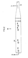
- Fig. 1 is a fragmentary side elevational view of a lead having four axially spaced electrodes and four axially spaced lead contacts;
- Fig. 2 is a fragmentary top view of a connector constructed according to the present invention having four connector contacts; and
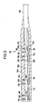
- Fig. 3 is a cross sectional view taken on line 3-3 of Fig. 2.
- In Fig. 1, an illustrative
prior art lead 10 includesbarrel electrodes distal portion 20. Electrodes 12-18 are mounted in a conventional manner onlead 10 as is well known in the prior art. The electrodes 12-16 are generally spaced in equal increments successively away from the mostdistal electrode 18. Each electrode 12-18 is connected to its individual conductor (not shown) withinlead 10 in a conventional manner. -
Lead 10 includes aproximal portion 22 on which are mountedlead contacts - When placed in the epidural space, any two of electrodes 12-18 may be selected for stimulation. For stimulating different portions, for example, any of the
pairs Electrodes -
Connector 32 is designed to receiveproximal portion 22 oflead 10.Connector 32 includes aconnector body 34 made of biocompatible material, such as molded silicone rubber in this embodiment.Connector body 34 is attached tolead extension 36, which is, in turn, connected to a source of electrical stimulation (not shown). -
Connector body 34 is provided with a central lead-receivingbore 38 sized to snugly receiveproximal portion 22 oflead 10. In this embodiment,bore 38 is cylindrical for the receipt of typicalprior art lead 10. - Mounted within
connector body 34 areconnectors openings connector body 34 frombore 38 to the external surface ofconnector body 34. Mounted through each opening 48-54 into connectors 40-46, are setscrews - Connectors 40-46 are made of 304 stainless steel in this embodiment. Connectors 40-46 include
connector contacts contacts conductor 72.Contacts conductor 74. Of course, in other embodiments, each contact has an individual conductor. - When one lead contact 24-30 is positioned within one connector 40-46, electrical contact is made between it and contact 64-70 of connectors 40-46. Electrical contact is also made by set screw 56-62 which is in electrical contact with
conductor -
Contacts 64―70 are positioned alongbore 38 ofconnector 32 in positions, the distance between which are multiples of the distance between each pair of contacts 24-30. In this embodiment, the distance betweenconnector contacts connector contacts contacts contacts contacts - Therefore,
connector 32 includes means to select combinations of contacts 24-30 oflead 10. The axial location of a lead 10 withinconnector 32 in this embodiment determines the contact 24-30 selection and, therefore, determines which two, and only two, of lead contacts 24-30 comes to contact with two of connector contacts 64-70. - For example, to select
contacts proximal portion 22 oflead 10 is inserted inbore 38 ofconnector 32 untilcontact 24 is in electrical contact withcontact 64. Because of the equal spacing,contact 26 is in electrical contact withcontact 66.Contacts contacts - To select
contacts proximal portion 22 oflead 10 is inserted inbore 38 ofconnector 32 untilconnector 24 is in electrical contact withcontact 68.Contact 26 then lies betweencontacts Contact 28 is in electrical contact withcontact 70. - To connect
contacts contact 24 is in electrical contact withconnector 66.Contact 30 is then in electrical contact withcontact 68.Contacts contacts - To connect
contacts contact 26 is in electrical contact withcontact 64.Contact 28 is then in electrical contact withcontact 66.Contacts contacts - To connect
electrodes connector 32 untilcontact 28 is in electrical contact withcontact 68. This positionscontact 30 in electrical contact withcontact 70.Contact 24 is out of contact in the area betweencontacts Contact 28 is out of contact in the area betweencontacts - Similarly, to connect
contacts connector 32 untilcontact 28electrically contacts contact 64.Contact 30 then contacts thecontact 66.Contacts past contact 64 and out of electrical connection. - Once
proximal portion 22 oflead 10 is properly positioned withinbore 38 ofconnector 32, the appropriate set screws 56-62 are tightened down upon contacts 24-30 to holdlead 10 fixedly withinconnector 32. - One skilled in the art may arrange other numbers and combinations of electrodes and contacts through this programming scheme. With this apparatus, multiple electrode leads may be connected to leads or pulse generators having a different number of electrodes. For example, a four pole lead may have two poles selected for connection to an implantable pulse generator. Similarly, polarity may be changed in the manner taught by Sluetz. While the invention has been disclosed in terms of a four electrode embodiment, one skilled in the art may determine many other embodiments with which to practice this invention.
Claims (3)
characterized in that there are at least three of said second contact surfaces (64-70), of which adjacent ones are spaced apart by a distance equal to nx, n being an integer, and n differing for adjacent pairs of contact surfaces which have a common contact surface.
Applications Claiming Priority (2)
| Application Number | Priority Date | Filing Date | Title |
|---|---|---|---|
| US701466 | 1985-02-14 | ||
| US06/701,466 US4603696A (en) | 1985-02-14 | 1985-02-14 | Lead connector |
Publications (3)
| Publication Number | Publication Date |
|---|---|
| EP0192082A2 EP0192082A2 (en) | 1986-08-27 |
| EP0192082A3 EP0192082A3 (en) | 1987-06-03 |
| EP0192082B1 true EP0192082B1 (en) | 1990-03-21 |
Family
ID=24817496
Family Applications (1)
| Application Number | Title | Priority Date | Filing Date |
|---|---|---|---|
| EP86100997A Expired EP0192082B1 (en) | 1985-02-14 | 1986-01-25 | Lead connector |
Country Status (5)
| Country | Link |
|---|---|
| US (1) | US4603696A (en) |
| EP (1) | EP0192082B1 (en) |
| JP (1) | JPS61240969A (en) |
| CA (1) | CA1266303A (en) |
| DE (1) | DE3669660D1 (en) |
Families Citing this family (40)
| Publication number | Priority date | Publication date | Assignee | Title |
|---|---|---|---|---|
| US4712557A (en) * | 1986-04-28 | 1987-12-15 | Cordis Leads, Inc. | A pacer including a multiple connector assembly with removable wedge and method of use |
| US4848352A (en) * | 1987-02-13 | 1989-07-18 | Telectronics, N.V. | Method for cardiac pacing and sensing using combination of electrodes |
| US4934367A (en) * | 1988-04-22 | 1990-06-19 | Medtronic, Inc. | In-line pacemaker connector system |
| DE3914677A1 (en) * | 1989-05-03 | 1990-11-08 | Alt Eckhard | ELECTRICAL CONNECTING DEVICE FOR PRODUCING MECHANICAL AND ELECTRICAL CONNECTIONS BETWEEN AN IMPLANTABLE MEDICAL DEVICE AND A DELIVERY SYSTEM |
| US5235742A (en) * | 1989-11-20 | 1993-08-17 | Siemens Pacesetter, Inc. | Method of making an implantable device |
| US5257622A (en) * | 1991-09-19 | 1993-11-02 | Medtronic, Inc. | Locking connector for implantable device |
| US5938624A (en) | 1997-09-10 | 1999-08-17 | Radi Medical Systems Ab | Male connector with a continous surface for a guide wire and method therefor |
| US7047671B2 (en) * | 2000-08-10 | 2006-05-23 | Cheryl Steed | Disposable shoe insert |
| US20040106964A1 (en) * | 2002-10-10 | 2004-06-03 | Fischer Elmar R. | Implantable Medical Device with Multiple Electrode Lead and Connector with Central Fastener |
| US20040106959A1 (en) * | 2002-10-10 | 2004-06-03 | Schmidt John A. | Implantable Medical Device with Multiple Electrode Lead |
| US7539542B1 (en) | 2003-01-09 | 2009-05-26 | Boston Scientific Neuromodulation Corporation | Lead connector, lead adapter, and lead insertion apparatus |
| US8078280B2 (en) * | 2003-04-25 | 2011-12-13 | Medtronic, Inc. | Implantable biomedical electrical connectors having integral side and inner walls |
| US7107104B2 (en) * | 2003-05-30 | 2006-09-12 | Medtronic, Inc. | Implantable cortical neural lead and method |
| US7337003B2 (en) * | 2005-01-25 | 2008-02-26 | Advanced Bionics Corporation | Implantable pulse generator case |
| US7583999B2 (en) | 2006-07-31 | 2009-09-01 | Cranial Medical Systems, Inc. | Multi-channel connector for brain stimulation system |
| WO2009114607A1 (en) * | 2008-03-12 | 2009-09-17 | Boston Scientific Neuromodulation Corporation | Low-profile connector for a neurostimulation lead |
| US8965482B2 (en) | 2010-09-30 | 2015-02-24 | Nevro Corporation | Systems and methods for positioning implanted devices in a patient |
| US8805519B2 (en) | 2010-09-30 | 2014-08-12 | Nevro Corporation | Systems and methods for detecting intrathecal penetration |
| US9472916B2 (en) | 2013-03-14 | 2016-10-18 | Medtronic, Inc. | Distal connector assemblies for medical lead extensions |
| US9314619B2 (en) | 2013-09-18 | 2016-04-19 | Greatbatch Ltd. | Connector apparatus for a medical device |
| US11051889B2 (en) | 2015-05-10 | 2021-07-06 | Alpha Omega Engineering Ltd. | Brain navigation methods and device |
| WO2016182997A2 (en) | 2015-05-10 | 2016-11-17 | Alpha Omega Neuro Technologies, Ltd. | Automatic brain probe guidance system |
| US11234632B2 (en) | 2015-05-10 | 2022-02-01 | Alpha Omega Engineering Ltd. | Brain navigation lead |
| US9956394B2 (en) | 2015-09-10 | 2018-05-01 | Boston Scientific Neuromodulation Corporation | Connectors for electrical stimulation systems and methods of making and using |
| US10342983B2 (en) | 2016-01-14 | 2019-07-09 | Boston Scientific Neuromodulation Corporation | Systems and methods for making and using connector contact arrays for electrical stimulation systems |
| US10201713B2 (en) | 2016-06-20 | 2019-02-12 | Boston Scientific Neuromodulation Corporation | Threaded connector assembly and methods of making and using the same |
| US10307602B2 (en) | 2016-07-08 | 2019-06-04 | Boston Scientific Neuromodulation Corporation | Threaded connector assembly and methods of making and using the same |
| US10543374B2 (en) | 2016-09-30 | 2020-01-28 | Boston Scientific Neuromodulation Corporation | Connector assemblies with bending limiters for electrical stimulation systems and methods of making and using same |
| US10905871B2 (en) | 2017-01-27 | 2021-02-02 | Boston Scientific Neuromodulation Corporation | Lead assemblies with arrangements to confirm alignment between terminals and contacts |
| WO2018160495A1 (en) | 2017-02-28 | 2018-09-07 | Boston Scientific Neuromodulation Corporation | Toolless connector for latching stimulation leads and methods of making and using |
| US10980999B2 (en) | 2017-03-09 | 2021-04-20 | Nevro Corp. | Paddle leads and delivery tools, and associated systems and methods |
| US10603499B2 (en) | 2017-04-07 | 2020-03-31 | Boston Scientific Neuromodulation Corporation | Tapered implantable lead and connector interface and methods of making and using |
| US10918873B2 (en) | 2017-07-25 | 2021-02-16 | Boston Scientific Neuromodulation Corporation | Systems and methods for making and using an enhanced connector of an electrical stimulation system |
| AU2018331512B2 (en) | 2017-09-15 | 2021-06-24 | Boston Scientific Neuromodulation Corporation | Actuatable lead connector for an operating room cable assembly and methods of making and using |
| US11045656B2 (en) | 2017-09-15 | 2021-06-29 | Boston Scientific Neuromodulation Corporation | Biased lead connector for operating room cable assembly and methods of making and using |
| US11139603B2 (en) | 2017-10-03 | 2021-10-05 | Boston Scientific Neuromodulation Corporation | Connectors with spring contacts for electrical stimulation systems and methods of making and using same |
| US11103712B2 (en) | 2018-01-16 | 2021-08-31 | Boston Scientific Neuromodulation Corporation | Connector assemblies with novel spacers for electrical stimulation systems and methods of making and using same |
| EP3758793A4 (en) | 2018-03-29 | 2021-12-08 | Nevro Corp. | Leads having sidewall openings, and associated systems and methods |
| EP3790623B1 (en) | 2018-05-11 | 2023-07-05 | Boston Scientific Neuromodulation Corporation | Connector assembly for an electrical stimulation system |
| US11357992B2 (en) | 2019-05-03 | 2022-06-14 | Boston Scientific Neuromodulation Corporation | Connector assembly for an electrical stimulation system and methods of making and using |
Family Cites Families (3)
| Publication number | Priority date | Publication date | Assignee | Title |
|---|---|---|---|---|
| US4236525A (en) * | 1978-11-22 | 1980-12-02 | Intermedics, Inc. | Multiple function lead assembly |
| US4469104A (en) * | 1982-07-16 | 1984-09-04 | Cordis Corporation | Multipolar connector for pacing lead |
| US4437474A (en) * | 1982-07-16 | 1984-03-20 | Cordis Corporation | Method for making multiconductor coil and the coil made thereby |
-
1985
- 1985-02-14 US US06/701,466 patent/US4603696A/en not_active Expired - Fee Related
-
1986
- 1986-01-25 EP EP86100997A patent/EP0192082B1/en not_active Expired
- 1986-01-25 DE DE8686100997T patent/DE3669660D1/en not_active Expired - Fee Related
- 1986-02-13 CA CA000501803A patent/CA1266303A/en not_active Expired - Lifetime
- 1986-02-14 JP JP61030610A patent/JPS61240969A/en active Granted
Also Published As
| Publication number | Publication date |
|---|---|
| DE3669660D1 (en) | 1990-04-26 |
| CA1266303A (en) | 1990-02-27 |
| JPS61240969A (en) | 1986-10-27 |
| EP0192082A3 (en) | 1987-06-03 |
| JPH0318471B2 (en) | 1991-03-12 |
| EP0192082A2 (en) | 1986-08-27 |
| US4603696A (en) | 1986-08-05 |
Similar Documents
| Publication | Publication Date | Title |
|---|---|---|
| EP0192082B1 (en) | Lead connector | |
| US9839787B2 (en) | Systems and methods for making and using connector contact arrays for electrical stimulation systems | |
| EP3229891B1 (en) | Systems with improved contact arrays for electrical stimulation systems | |
| US10342983B2 (en) | Systems and methods for making and using connector contact arrays for electrical stimulation systems | |
| US8260424B2 (en) | Systems and methods for detecting a loss of electrical connectivity between components of implantable medical lead systems | |
| US4236525A (en) | Multiple function lead assembly | |
| USRE31990E (en) | Multiple function lead assembly and method for inserting assembly into an implantable tissue stimulator | |
| US11224743B2 (en) | Systems and methods for making and using modular leads for electrical stimulation systems | |
| US7904161B2 (en) | Lead adaptor having low resistance conductors and/or encapsulated housing | |
| US8046074B2 (en) | High-resolution connector for a neurostimulation lead | |
| US10258801B2 (en) | Varying lead configuration implantable medical device | |
| US20170143978A1 (en) | Connector for electrical stimulation and methods of making and using | |
| US20050137665A1 (en) | Implantabel electrical connector system | |
| US20040068303A1 (en) | Implantable cardiac system with a selectable active housing | |
| EP2456518A1 (en) | Multi-port modular connector for implantable electrical stimulation systems and methods of making and using | |
| DE3914677C2 (en) | ||
| US20150051677A1 (en) | Control module with port for receiving one or two leads and systems and methods using the control module | |
| US20130282091A1 (en) | Systems and methods for making and using improved electrodes for implantable paddle leads | |
| US11918821B2 (en) | Connector for use in overmolded header of implantable pulse generator | |
| US11458303B2 (en) | Implantable medical leads having fewer conductors than distal electrodes | |
| US6687542B2 (en) | XY selectable lead assembly | |
| US20170232264A1 (en) | Micro extension connector for electrical stimulation systems |
Legal Events
| Date | Code | Title | Description |
|---|---|---|---|
| PUAI | Public reference made under article 153(3) epc to a published international application that has entered the european phase |
Free format text: ORIGINAL CODE: 0009012 |
|
| AK | Designated contracting states |
Kind code of ref document: A2 Designated state(s): DE FR GB IT NL SE |
|
| PUAL | Search report despatched |
Free format text: ORIGINAL CODE: 0009013 |
|
| AK | Designated contracting states |
Kind code of ref document: A3 Designated state(s): DE FR GB IT NL SE |
|
| 17P | Request for examination filed |
Effective date: 19870509 |
|
| 17Q | First examination report despatched |
Effective date: 19881013 |
|
| ITF | It: translation for a ep patent filed |
Owner name: BARZANO' E ZANARDO ROMA S.P.A. |
|
| GRAA | (expected) grant |
Free format text: ORIGINAL CODE: 0009210 |
|
| AK | Designated contracting states |
Kind code of ref document: B1 Designated state(s): DE FR GB IT NL SE |
|
| ET | Fr: translation filed | ||
| REF | Corresponds to: |
Ref document number: 3669660 Country of ref document: DE Date of ref document: 19900426 |
|
| PLBI | Opposition filed |
Free format text: ORIGINAL CODE: 0009260 |
|
| 26 | Opposition filed |
Opponent name: BIOTRONIK MESS- UND THERAPIEGERAETE GMBH & CO ING Effective date: 19901221 |
|
| NLR1 | Nl: opposition has been filed with the epo |
Opponent name: BIOTRONIK MESS- UND THERAPIEGERAETE GMBH & CO. |
|
| PGFP | Annual fee paid to national office [announced via postgrant information from national office to epo] |
Ref country code: SE Payment date: 19921211 Year of fee payment: 8 |
|
| PGFP | Annual fee paid to national office [announced via postgrant information from national office to epo] |
Ref country code: GB Payment date: 19921231 Year of fee payment: 8 |
|
| ITTA | It: last paid annual fee | ||
| PGFP | Annual fee paid to national office [announced via postgrant information from national office to epo] |
Ref country code: DE Payment date: 19931217 Year of fee payment: 9 |
|
| PGFP | Annual fee paid to national office [announced via postgrant information from national office to epo] |
Ref country code: FR Payment date: 19940112 Year of fee payment: 9 |
|
| PG25 | Lapsed in a contracting state [announced via postgrant information from national office to epo] |
Ref country code: GB Effective date: 19940125 |
|
| PG25 | Lapsed in a contracting state [announced via postgrant information from national office to epo] |
Ref country code: SE Effective date: 19940126 |
|
| PGFP | Annual fee paid to national office [announced via postgrant information from national office to epo] |
Ref country code: NL Payment date: 19940131 Year of fee payment: 9 |
|
| GBPC | Gb: european patent ceased through non-payment of renewal fee |
Effective date: 19940125 |
|
| EUG | Se: european patent has lapsed |
Ref document number: 86100997.5 Effective date: 19940810 |
|
| PG25 | Lapsed in a contracting state [announced via postgrant information from national office to epo] |
Ref country code: NL Effective date: 19950801 |
|
| PG25 | Lapsed in a contracting state [announced via postgrant information from national office to epo] |
Ref country code: FR Effective date: 19950929 |
|
| NLV4 | Nl: lapsed or anulled due to non-payment of the annual fee |
Effective date: 19950801 |
|
| PG25 | Lapsed in a contracting state [announced via postgrant information from national office to epo] |
Ref country code: DE Effective date: 19951003 |
|
| REG | Reference to a national code |
Ref country code: FR Ref legal event code: ST |
|
| APAC | Appeal dossier modified |
Free format text: ORIGINAL CODE: EPIDOS NOAPO |
|
| RDAH | Patent revoked |
Free format text: ORIGINAL CODE: EPIDOS REVO |
|
| RDAG | Patent revoked |
Free format text: ORIGINAL CODE: 0009271 |
|
| STAA | Information on the status of an ep patent application or granted ep patent |
Free format text: STATUS: PATENT REVOKED |
|
| 27W | Patent revoked |
Effective date: 19960523 |
|
| APAH | Appeal reference modified |
Free format text: ORIGINAL CODE: EPIDOSCREFNO |