EP0191202A2 - Optical fibres doped with fluorine and process for their production - Google Patents
Optical fibres doped with fluorine and process for their production Download PDFInfo
- Publication number
- EP0191202A2 EP0191202A2 EP85202113A EP85202113A EP0191202A2 EP 0191202 A2 EP0191202 A2 EP 0191202A2 EP 85202113 A EP85202113 A EP 85202113A EP 85202113 A EP85202113 A EP 85202113A EP 0191202 A2 EP0191202 A2 EP 0191202A2
- Authority
- EP
- European Patent Office
- Prior art keywords
- optical
- fluorine
- optical fiber
- substance
- losses
- Prior art date
- Legal status (The legal status is an assumption and is not a legal conclusion. Google has not performed a legal analysis and makes no representation as to the accuracy of the status listed.)
- Granted
Links
- 230000003287 optical effect Effects 0.000 title claims abstract description 31
- 229910052731 fluorine Inorganic materials 0.000 title claims abstract description 28
- 239000011737 fluorine Substances 0.000 title claims abstract description 28
- 238000000034 method Methods 0.000 title claims description 16
- 238000004519 manufacturing process Methods 0.000 title claims description 10
- 230000008569 process Effects 0.000 title description 11
- PXGOKWXKJXAPGV-UHFFFAOYSA-N Fluorine Chemical compound FF PXGOKWXKJXAPGV-UHFFFAOYSA-N 0.000 title 1
- 239000013307 optical fiber Substances 0.000 claims abstract description 30
- YCKRFDGAMUMZLT-UHFFFAOYSA-N Fluorine atom Chemical compound [F] YCKRFDGAMUMZLT-UHFFFAOYSA-N 0.000 claims abstract description 28
- VYPSYNLAJGMNEJ-UHFFFAOYSA-N Silicium dioxide Chemical compound O=[Si]=O VYPSYNLAJGMNEJ-UHFFFAOYSA-N 0.000 claims abstract description 16
- 239000000126 substance Substances 0.000 claims abstract description 14
- 235000012239 silicon dioxide Nutrition 0.000 claims abstract description 6
- 239000000377 silicon dioxide Substances 0.000 claims abstract description 6
- 239000000463 material Substances 0.000 claims description 28
- 230000008021 deposition Effects 0.000 claims description 20
- 239000007789 gas Substances 0.000 claims description 16
- 239000000203 mixture Substances 0.000 claims description 8
- YBMRDBCBODYGJE-UHFFFAOYSA-N germanium dioxide Chemical compound O=[Ge]=O YBMRDBCBODYGJE-UHFFFAOYSA-N 0.000 claims description 7
- 239000012495 reaction gas Substances 0.000 claims description 7
- 239000007795 chemical reaction product Substances 0.000 claims description 6
- 239000000654 additive Substances 0.000 claims description 5
- 230000000996 additive effect Effects 0.000 claims description 4
- 239000002019 doping agent Substances 0.000 claims description 3
- 229940119177 germanium dioxide Drugs 0.000 claims description 3
- 238000005245 sintering Methods 0.000 claims description 3
- 239000011521 glass Substances 0.000 claims description 2
- 239000012535 impurity Substances 0.000 abstract description 10
- 230000009467 reduction Effects 0.000 abstract description 6
- 238000005336 cracking Methods 0.000 abstract description 2
- 239000000835 fiber Substances 0.000 description 24
- 238000000151 deposition Methods 0.000 description 17
- 238000010521 absorption reaction Methods 0.000 description 13
- 238000005253 cladding Methods 0.000 description 8
- VEXZGXHMUGYJMC-UHFFFAOYSA-M Chloride anion Chemical compound [Cl-] VEXZGXHMUGYJMC-UHFFFAOYSA-M 0.000 description 6
- 229910004298 SiO 2 Inorganic materials 0.000 description 6
- 229910003910 SiCl4 Inorganic materials 0.000 description 4
- FDNAPBUWERUEDA-UHFFFAOYSA-N silicon tetrachloride Chemical compound Cl[Si](Cl)(Cl)Cl FDNAPBUWERUEDA-UHFFFAOYSA-N 0.000 description 4
- 229910003902 SiCl 4 Inorganic materials 0.000 description 3
- 230000008859 change Effects 0.000 description 3
- 150000001875 compounds Chemical class 0.000 description 3
- 230000002349 favourable effect Effects 0.000 description 3
- 238000005457 optimization Methods 0.000 description 3
- 239000000758 substrate Substances 0.000 description 3
- IEXRMSFAVATTJX-UHFFFAOYSA-N tetrachlorogermane Chemical compound Cl[Ge](Cl)(Cl)Cl IEXRMSFAVATTJX-UHFFFAOYSA-N 0.000 description 3
- 229910006113 GeCl4 Inorganic materials 0.000 description 2
- 229910005793 GeO 2 Inorganic materials 0.000 description 2
- 230000008901 benefit Effects 0.000 description 2
- 238000010348 incorporation Methods 0.000 description 2
- 238000001228 spectrum Methods 0.000 description 2
- 238000002207 thermal evaporation Methods 0.000 description 2
- 240000003517 Elaeocarpus dentatus Species 0.000 description 1
- QVGXLLKOCUKJST-UHFFFAOYSA-N atomic oxygen Chemical compound [O] QVGXLLKOCUKJST-UHFFFAOYSA-N 0.000 description 1
- 230000015572 biosynthetic process Effects 0.000 description 1
- 238000006243 chemical reaction Methods 0.000 description 1
- 239000011248 coating agent Substances 0.000 description 1
- 238000000576 coating method Methods 0.000 description 1
- 238000011109 contamination Methods 0.000 description 1
- 238000005137 deposition process Methods 0.000 description 1
- 230000000994 depressogenic effect Effects 0.000 description 1
- YWEUIGNSBFLMFL-UHFFFAOYSA-N diphosphonate Chemical compound O=P(=O)OP(=O)=O YWEUIGNSBFLMFL-UHFFFAOYSA-N 0.000 description 1
- 238000009826 distribution Methods 0.000 description 1
- 238000005530 etching Methods 0.000 description 1
- 238000002474 experimental method Methods 0.000 description 1
- 238000013213 extrapolation Methods 0.000 description 1
- 238000011835 investigation Methods 0.000 description 1
- 238000002156 mixing Methods 0.000 description 1
- 229910052760 oxygen Inorganic materials 0.000 description 1
- 239000001301 oxygen Substances 0.000 description 1
- DLYUQMMRRRQYAE-UHFFFAOYSA-N phosphorus pentoxide Inorganic materials O1P(O2)(=O)OP3(=O)OP1(=O)OP2(=O)O3 DLYUQMMRRRQYAE-UHFFFAOYSA-N 0.000 description 1
- 230000008092 positive effect Effects 0.000 description 1
- 230000000717 retained effect Effects 0.000 description 1
- 238000000926 separation method Methods 0.000 description 1
- 238000012360 testing method Methods 0.000 description 1
- QERYCTSHXKAMIS-UHFFFAOYSA-M thiophene-2-carboxylate Chemical compound [O-]C(=O)C1=CC=CS1 QERYCTSHXKAMIS-UHFFFAOYSA-M 0.000 description 1
Images

Classifications
-
- G—PHYSICS
- G02—OPTICS
- G02B—OPTICAL ELEMENTS, SYSTEMS OR APPARATUS
- G02B6/00—Light guides; Structural details of arrangements comprising light guides and other optical elements, e.g. couplings
- G02B6/02—Optical fibres with cladding with or without a coating
- G02B6/036—Optical fibres with cladding with or without a coating core or cladding comprising multiple layers
- G02B6/03616—Optical fibres characterised both by the number of different refractive index layers around the central core segment, i.e. around the innermost high index core layer, and their relative refractive index difference
- G02B6/03622—Optical fibres characterised both by the number of different refractive index layers around the central core segment, i.e. around the innermost high index core layer, and their relative refractive index difference having 2 layers only
- G02B6/03627—Optical fibres characterised both by the number of different refractive index layers around the central core segment, i.e. around the innermost high index core layer, and their relative refractive index difference having 2 layers only arranged - +
-
- C—CHEMISTRY; METALLURGY
- C03—GLASS; MINERAL OR SLAG WOOL
- C03B—MANUFACTURE, SHAPING, OR SUPPLEMENTARY PROCESSES
- C03B37/00—Manufacture or treatment of flakes, fibres, or filaments from softened glass, minerals, or slags
- C03B37/01—Manufacture of glass fibres or filaments
- C03B37/012—Manufacture of preforms for drawing fibres or filaments
- C03B37/014—Manufacture of preforms for drawing fibres or filaments made entirely or partially by chemical means, e.g. vapour phase deposition of bulk porous glass either by outside vapour deposition [OVD], or by outside vapour phase oxidation [OVPO] or by vapour axial deposition [VAD]
- C03B37/01413—Reactant delivery systems
-
- C—CHEMISTRY; METALLURGY
- C03—GLASS; MINERAL OR SLAG WOOL
- C03B—MANUFACTURE, SHAPING, OR SUPPLEMENTARY PROCESSES
- C03B37/00—Manufacture or treatment of flakes, fibres, or filaments from softened glass, minerals, or slags
- C03B37/01—Manufacture of glass fibres or filaments
- C03B37/012—Manufacture of preforms for drawing fibres or filaments
- C03B37/014—Manufacture of preforms for drawing fibres or filaments made entirely or partially by chemical means, e.g. vapour phase deposition of bulk porous glass either by outside vapour deposition [OVD], or by outside vapour phase oxidation [OVPO] or by vapour axial deposition [VAD]
- C03B37/018—Manufacture of preforms for drawing fibres or filaments made entirely or partially by chemical means, e.g. vapour phase deposition of bulk porous glass either by outside vapour deposition [OVD], or by outside vapour phase oxidation [OVPO] or by vapour axial deposition [VAD] by glass deposition on a glass substrate, e.g. by inside-, modified-, plasma-, or plasma modified- chemical vapour deposition [ICVD, MCVD, PCVD, PMCVD], i.e. by thin layer coating on the inside or outside of a glass tube or on a glass rod
- C03B37/01807—Reactant delivery systems, e.g. reactant deposition burners
- C03B37/01815—Reactant deposition burners or deposition heating means
- C03B37/01823—Plasma deposition burners or heating means
- C03B37/0183—Plasma deposition burners or heating means for plasma within a tube substrate
-
- C—CHEMISTRY; METALLURGY
- C03—GLASS; MINERAL OR SLAG WOOL
- C03C—CHEMICAL COMPOSITION OF GLASSES, GLAZES OR VITREOUS ENAMELS; SURFACE TREATMENT OF GLASS; SURFACE TREATMENT OF FIBRES OR FILAMENTS MADE FROM GLASS, MINERALS OR SLAGS; JOINING GLASS TO GLASS OR OTHER MATERIALS
- C03C13/00—Fibre or filament compositions
- C03C13/04—Fibre optics, e.g. core and clad fibre compositions
- C03C13/045—Silica-containing oxide glass compositions
-
- C—CHEMISTRY; METALLURGY
- C03—GLASS; MINERAL OR SLAG WOOL
- C03B—MANUFACTURE, SHAPING, OR SUPPLEMENTARY PROCESSES
- C03B2201/00—Type of glass produced
- C03B2201/06—Doped silica-based glasses
- C03B2201/08—Doped silica-based glasses doped with boron or fluorine or other refractive index decreasing dopant
- C03B2201/12—Doped silica-based glasses doped with boron or fluorine or other refractive index decreasing dopant doped with fluorine
-
- C—CHEMISTRY; METALLURGY
- C03—GLASS; MINERAL OR SLAG WOOL
- C03B—MANUFACTURE, SHAPING, OR SUPPLEMENTARY PROCESSES
- C03B2201/00—Type of glass produced
- C03B2201/06—Doped silica-based glasses
- C03B2201/30—Doped silica-based glasses doped with metals, e.g. Ga, Sn, Sb, Pb or Bi
- C03B2201/31—Doped silica-based glasses doped with metals, e.g. Ga, Sn, Sb, Pb or Bi doped with germanium
-
- C—CHEMISTRY; METALLURGY
- C03—GLASS; MINERAL OR SLAG WOOL
- C03B—MANUFACTURE, SHAPING, OR SUPPLEMENTARY PROCESSES
- C03B2203/00—Fibre product details, e.g. structure, shape
- C03B2203/10—Internal structure or shape details
- C03B2203/22—Radial profile of refractive index, composition or softening point
Definitions
- the invention relates to an optical fiber based on silicon dioxide with a fluorine doping which determines its refractive index profile at least in the optical line region.
- the invention relates to a method for producing such an optical fiber, in which a preform is produced by reactive deposition of silicon dioxide and fluorine from a reaction gas mixture and is processed further to form the optical fiber.
- the preform is usually further processed into optical fibers by collapsing and / or pulling.
- Optical fibers of the aforementioned type are known from DE-A-3 205 345.
- optical fibers with fluorine doping are known, in which the refractive index profile is determined not by fluorine doping but by other substances, while by fluorine doping e.g. undesired refractive index fluctuations are eliminated (DE-A-3 031 147) or a low OH absorption is achieved (DE-A-3 318 589).
- the manufacturing processes of the type mentioned at the outset include the thermal deposition processes OVPO, MCVD and VAD and the PCVD process are known; see.
- the object of the invention is to provide measures with which the properties of fluorine-doped optical fibers are further improved in the above-mentioned partial areas.
- the use of such measures is intended in particular to reduce the influence of the drawing conditions on the optical properties (Rayleigh scattering and wavelength-independent 'c-term' losses), and the production of fluorine-doped optical fibers with Rayleigh scattering losses in the area of the material-intrinsic limits for pure Si0 2 with low levels Enable c-term losses and - for high fluorine doping concentrations - further reduce OH absorption losses.
- the advantages of fluorine doping in relation to all other optical properties are to be retained in full.
- an optical fiber of the type mentioned contains at least one substance which increases the coefficient of thermal expansion and which is uniformly distributed at least in the optical line region of the optical fiber.
- an optical fiber of the type mentioned at the outset has, in addition to the fluorine doping, which mainly determines the refractive index, a codoping, at least in the light-conducting region of the fiber, with at least one further substance which increases the coefficient of thermal expansion.
- a method of the type mentioned at the outset is preferably used to produce the optical fiber according to the invention, in which a constant amount of at least one reactive additive is added to the reaction gas mixture, at least during the deposition of the optical line region, the reaction product of which increases the coefficient of thermal expansion of the deposited material.
- the reaction products of the reactive additional substances are e.g. Phosphorus pentoxide or germanium dioxide into consideration.
- germanium dioxide is preferably used, i.e. Germanium tetrachloride is added to the reaction gas mixture.
- This additional substance has the advantage that there is no negative influence on the optical properties; in particular, there are no additional losses due to IR absorption in the range from 1.3 to 1.6 ⁇ m.
- the content of the reaction product of the additive is preferably 0.5 to 3.0 mol%, i.e. the content of additional substance in the reactive gas phase is chosen so that the concentration of the reaction product in the deposited material is preferably 0.5 to 3.0 mol%.
- the desired change in the coefficient of thermal expansion is in most cases not yet sufficiently high, while above this range the intrinsic Rayleigh scattering losses, which increase with the concentration of the doping, in some cases already have a clearly negative influence on the optical properties of the optical fibers.
- the PCVD process is preferably used for reactive deposition, ie compact glass layers are produced directly without sintering.
- the PCVD method allows namely in a particularly efficient and simple manner, both the deposition of pure Si0 2 as well (2.10-2>) luordot mich the production of profile structures with high optical refractive index differences by a pure F.
- thermal deposition processes In this case, OVPO, MCVD and VAD arise in principle due to the high sintering temperatures required for pure SiO 2 and the process yields which are massively reduced at high fluorine concentrations as a result of etching reactions.
- optical fibers with high fluorine doping - The positive influence on the optical properties - in particular of optical fibers with high fluorine doping - is independent of the special profile structure, i.e. for monomode and gradient multimode fibers alike.
- Typical values for the Rayleigh scattering loss term ⁇ R in different fiber types are: ⁇ R ⁇ 0.9 to 1.0 dB around 4 / km (monomode fiber, ⁇ CO ⁇ 0.3%) ⁇ R ⁇ 1.1 to 1 .3 dB nm 4 / k m (gradient index multimode fiber, ⁇ CO ⁇ 1.0%) or
- ⁇ R ⁇ 1.5 to 1.7 dB ⁇ m 4 / km (multimode fiber with high aperture, ⁇ CO ⁇ 2.0%).
- ⁇ CO is the relative, maximum difference in refractive index between the core and cladding material of the optical fiber.
- the Rayleigh scattering losses in this material system are largely independent of the drawing conditions, the manufacturing process and also any small amounts of codoping used (such as C 2 F 6 ); Residual influences are already included in the above data.
- Wavelength independent optical scattering losses (c-terms) can be iehprozeß Installation in this material system for all the above mentioned types of fibers negligibly small with optimized production and Z - that is, typically less than 0.1 dB / km - hold.
- the codoping according to the invention consequently improves the optical properties of fluorine-doped optical fibers, in particular with regard to reducing negative pulling influences, reducing the contributions of Rayleigh scattering, wavelength-independent scattering losses and additional absorption losses due to OH impurities.
- the cracking in the collapsed preforms is largely suppressed.
- the positive effect is also independent of the special profile structure of the optical fibers produced, i.e. the optical properties are improved equally in the production of fluorine-doped multimode and monomode fibers.
- the production of optical fibers with different profile structures is illustrated using a few exemplary embodiments.
- the variation of Q C2F6 in the core area was carried out so that a parabolic refractive index profile with a maximum, relative refractive index difference of ⁇ CO ⁇ 2% was achieved in the final preform.
- the maximum C 2 F 6 concentration in the chloride gas phase was thus about 13 mol% and the average deposition rate was about 0.3 g / min.
- Example 1 Pure fluorine doping (SiO 2 / F material system)
- the preforms produced without the use of Ge0 2 codoping with the PCVD process were drawn out into fibers with different drawing conditions and measured optically: Pulling out at 10 m / min at an oven temperature of 2100 ° C (drawing force F Z ⁇ 0.08N) resulted thereby to Rayleigh scatter losses of 1.5 dB.pm 4 / km and c-term losses of 2.5 dB / km; a drawing speed of 20 m / min at a drawing temperature of about 2000 ° C (drawing force F Z F0.46N) resulted in a change in the corresponding optical scattering loss terms to values of 2.5 dB.pm 4 / km or 0.5 dB / km.
- the absorption loss due to OH contamination was between 10 to 15 dB / km at 1.38 pm in both cases.
- Example 2 Fluorine doping with GeO 2 codotation (SiO 2 / F / GeO 2 material system)
- Monomode fibers with the refractive index profiles shown schematically in FIGS. 3 and 4 were produced under the same deposition conditions as in Examples 1 and 2.
- the refractive index profiles of both fiber preforms are largely identical. Fibers were drawn from both preforms under the same conditions and characterized for their optical losses.
- the fiber according to Example 3 shows a high Rayleigh scattering term of 3.15 dB.pm 4 / km, the fiber produced by the process according to the invention (example 4), in which the deposited material has a higher expansion coefficient than the surrounding jacket due to the Ge0 2 added , has a low Rayleigh scattering term of 1 , 14 dB.pm 4 / km.
Landscapes
- Chemical & Material Sciences (AREA)
- Engineering & Computer Science (AREA)
- Geochemistry & Mineralogy (AREA)
- Materials Engineering (AREA)
- Organic Chemistry (AREA)
- Life Sciences & Earth Sciences (AREA)
- Chemical Kinetics & Catalysis (AREA)
- General Chemical & Material Sciences (AREA)
- Physics & Mathematics (AREA)
- General Life Sciences & Earth Sciences (AREA)
- Manufacturing & Machinery (AREA)
- Optics & Photonics (AREA)
- General Physics & Mathematics (AREA)
- Plasma & Fusion (AREA)
- Manufacture, Treatment Of Glass Fibers (AREA)
- Glass Compositions (AREA)
- Optical Fibers, Optical Fiber Cores, And Optical Fiber Bundles (AREA)
Abstract
0 Eine Lichtleitfaser auf der Basis von Siliziumdioxid mit einer deren Brechungsindexprofil zumindest im optischen Leitungsbereich bestimmenden Fluordotierung enthält mindestens eine den thermischen Ausdehnungskoeffizienten erhöhende Substanz, die zumindest im optischen Leitungsbereich gleichmäßig verteilt ist. Durch die gleichmäßig verteilte Substanz wird der Einfluß der Ziehkraft Fz (beim Ausziehen der Vorform) auf die Rayleigh-Streuung aR und die wellenlängenunabhängigen 'c-Term'-Verluste c reduziert, und auch bei hohen Fluor-Dotierungskonzentrationen werden niedrige Rayleigh-Streuverluste im Bereich der materialintrinsischen Daten von reinem Siliziumdioxid erreicht. Zusätzlich wird eine weitere Reduktion des Gehalts an OH-Verunreinigungen bewirkt und eine Rißbildung in den kollabierten Vorformen wird weitgehend vermieden.
Description
Die Erfindung betrifft eine Lichtleitfaser auf der Basis von Siliziumdioxid mit einer deren Brechungsindexprofil zumindest im optischen Leitungsbereich bestimmenden Fluordotierung.The invention relates to an optical fiber based on silicon dioxide with a fluorine doping which determines its refractive index profile at least in the optical line region.
Ferner betrifft die Erfindung ein Verfahren zur Herstellung einer derartigen Lichtleitfaser, bei dem durch reaktive Abscheidung von Siliziumdioxid und Fluor aus einem Reaktionsgasgemisch eine Vorform erzeugt wird, die zur Lichtleitfaser weiterverarbeitet wird. Die Weiterverarbeitung der Vorform zur Lichtleitfaser erfolgt meist durch Kollabieren und/oder Ziehen.Furthermore, the invention relates to a method for producing such an optical fiber, in which a preform is produced by reactive deposition of silicon dioxide and fluorine from a reaction gas mixture and is processed further to form the optical fiber. The preform is usually further processed into optical fibers by collapsing and / or pulling.
Lichtleitfasern der zuvor genannten Art sind aus der DE-A-3 205 345 bekannt. Daneben sind Lichtleitfasern mit Fluordotierung bekannt, bei denen das Brechungsindexprofil nicht durch die Fluordotierung, sondern durch andere Substanzen bestimmt wird, während durch die Fluordotierung z.B. unerwünschte Brechungsindexschwankungen beseitigt werden (DE-A-3 031 147) oder eine niedrige OH-Absorption erreicht wird (DE-A-3 318 589).Optical fibers of the aforementioned type are known from DE-A-3 205 345. In addition, optical fibers with fluorine doping are known, in which the refractive index profile is determined not by fluorine doping but by other substances, while by fluorine doping e.g. undesired refractive index fluctuations are eliminated (DE-A-3 031 147) or a low OH absorption is achieved (DE-A-3 318 589).
Ferner ist es aus der DE-B-2 715 333 bekannt, die thermischen Ausdehnungskoeffizienten von Kern und Mantel einer Lichtleitfaser-Vorform durch Zusätze aneinander anzugleichen, um eine Rißbildung zu vermeiden.Furthermore, it is known from DE-B-2 715 333 to match the thermal expansion coefficients of the core and cladding of an optical fiber preform to one another by means of additives in order to avoid crack formation.
Als Herstellungsverfahren der eingangs genannten Art sind u.a. die thermischen Abscheidungsverfahren OVPO, MCVD und VAD sowie das PCVD-Verfahren bekannt; vgl.The manufacturing processes of the type mentioned at the outset include the thermal deposition processes OVPO, MCVD and VAD and the PCVD process are known; see.
Die ausschließliche Verwendung fluorhaltiger Verbindungen als Dotierungsmittel zur Einstellung des Brechungsindexprofils bietet die Möglichkeit der Herstellung von Lichtleitfasern mit Profilstrukturen, deren Zentralbereich weitgehend aus reinem Si02 bestehen kann. Besonders vorteilhaft sind dabei das Vermeiden kollabierbedingter Profilstörungen (zentraler 'Dips'), die - im Vergleich zu anderen Dotierungssystemen - niedrigen intrinsischen Streuverluste von Si02, die günstigen materialdispersiven Eigenschaften dieses Systems für Monomodeanwendungen und die vergleichsweise niedrigen Kosten für die fluorhaltigen Ausgangssubstanzen. Darüber hinaus lassen sich spezielle Profilstrukturen, z.B. "vollständig abgesenkte" ("fully depressed") Monomode-Strukturen (in denen die Brechungsindexverteilungen des lichtleitenden Bereichs unter dem Brechungsindex von Si02 liegen) und Multimode-Strukturen mit hoher numerischer Apertur, besonders einfach realisieren. Bei den Untersuchungen, die zur Erfindung geführt haben, zeigte sich jedoch, daß in folgenden Teilbereichen vorteilhafte optische Eigenschaften nur mit Einschränkungen erzielt werden konnten:
- 1. Die materialintrinsischen Rayleigh-Streuverluste von reinem Si02 wurden auch bei Lichtleitfasern mit günstigen Profilstrukturen (Si02'im Kern, Fluor/Sio2 im Mantel) experimentell nicht erreicht.
- 2. Bei rein fluordotierten Lichtleitfasern wurde eine - im Vergleich zu anderen Dotierungssystemen - deutliche Abhängigkeit der optischen Verluste von den Ziehbedingungen festgestellt. Rayleigh-Streuung und wellenlängenunabhängige Streuverluste ('c-Term') hängen dabei beide insbesondere von der Ziehkraft ab, mit der die Faser aus der Vorform gezogen wird: Hohe Ziehkräfte führen zu niedrigen c-Termen und erhöhten Rayleigh-Streuverlusten, niedrige Ziehkräfte dagegen in der Regel zu erhöhten c-Termen bei gleichzeitig niedrigen Rayleigh-Termen. Dieses Verhalten ist für eine absolute Optimierung des Ziehprozesses problematisch; darüber hinaus sind die relativ 'optimalen Ziehbedingungen' für das reine Fluordotierungssystem deutlich von denen anderer Dotierungssysteme (z.B. Ge02) verschieden.
- 3. Es wurde experimentell gefunden, daß die Erhöhung des Anteils fluorhaltiger Verbindungen im Reaktionsgasgemisch auf Konzentrationen von mehr als 2 bis 3 mol% (bezogen auf die Chlorid-Gasanteile) nicht zu einer weiter reduzierten OH-Absorption führt; für hohe Fluor-Dotierungskonzentrationen (maximale Brechungsindexunterschiede zwischen Kern und Mantel größer als typischerweise A n~1,5.10-2) wurden sogar teilweise höhere OH-Absorptionsverluste, d.h. Absorptionsverluste durch OH-Verunreinigungen, als in Fasern mit niedrigen Fluordotierungskonzentrationen beobachtet.
- 4. Trotz der in etwa vergleichbaren thermischen Ausdehnungskoeffizienten von reinem Si02 und fluordotiertem Si02 traten im Mantel der kollabierten Vorform in verstärktem Maße Risse auf.
- 1. The material intrinsic Rayleigh scattering losses of pure Si0 2 were not experimentally achieved even with optical fibers with favorable profile structures (Si0 2 'in the core, fluorine / Sio 2 in the cladding).
- 2. In the case of purely fluorine-doped optical fibers, a clear dependence of the optical losses on the drawing conditions was found, compared to other doping systems. Rayleigh scattering and wavelength-independent scattering losses ('c-term') both depend in particular on the pulling force with which the fiber is drawn from the preform: high pulling forces lead to low c-terms and increased Rayleigh scattering losses, while low pulling forces in the Rule for increased c-terms with low Rayleigh terms. This behavior is problematic for an absolute optimization of the drawing process; in addition, the relatively 'optimal pulling conditions' for the pure fluorine doping system are clearly different from those of other doping systems (eg Ge0 2 ).
- 3. It has been found experimentally that increasing the proportion of fluorine-containing compounds in the reaction gas mixture to concentrations of more than 2 to 3 mol% (based on the chloride gas proportions) does not lead to a further reduced OH absorption; for high fluorine doping concentrations (maximum refractive index differences between core and cladding greater than typically A n ~ 1.5.10 -2 ), in some cases higher OH absorption losses, ie absorption losses due to OH impurities, were observed than in fibers with low fluorine doping concentrations.
- 4. Despite the roughly comparable thermal expansion coefficients of pure Si0 2 and fluorine-doped Si0 2 , cracks occurred to an increased extent in the jacket of the collapsed preform.
Aufgabe der Erfindung ist es, Maßnahmen anzugeben, mit denen die Eigenschaften fluordotierter Lichtleitfasern in den o.a. Teilbereichen weiter verbessert werden. Die Anwendung derartiger Maßnahmen soll insbesondere den Einfluß der Ziehbedingungen auf die optischen Eigenschaften (Rayleigh-Streuung und wellenlängenunabhängige 'c-Term'-Verluste) reduzieren, die Herstellung fluordotierter Lichtleitfasern mit Rayleigh-Streuverlusten im Bereich der materialintrinsischen Grenzen für reines Si02 bei gleichzeitig niedrigen c-Term-Verlusten ermöglichen und - für hohe Fluor-Dotierungskonzentrationen - weiter verringerte OH-Absorptionsverluste bewirken. Gleichzeitig sollen jedoch die Vorteile der Fluordotierung in bezug auf sämtliche weitere optische Eigenschaften in vollem Umfang erhalten bleiben.The object of the invention is to provide measures with which the properties of fluorine-doped optical fibers are further improved in the above-mentioned partial areas. The use of such measures is intended in particular to reduce the influence of the drawing conditions on the optical properties (Rayleigh scattering and wavelength-independent 'c-term' losses), and the production of fluorine-doped optical fibers with Rayleigh scattering losses in the area of the material-intrinsic limits for pure Si0 2 with low levels Enable c-term losses and - for high fluorine doping concentrations - further reduce OH absorption losses. At the same time However, the advantages of fluorine doping in relation to all other optical properties are to be retained in full.
Diese Aufgabe wird erfindungsgemäß dadurch gelöst, daß eine Lichtleitfaser der eingangs genannten Art einen Gehalt an mindestens einer den thermischen Ausdehnungskoeffizienten erhöhenden Substanz, die zumindest im optischen Leitungsbereich der Lichtleitfaser gleichmäßig verteilt ist, aufweist.This object is achieved in that an optical fiber of the type mentioned contains at least one substance which increases the coefficient of thermal expansion and which is uniformly distributed at least in the optical line region of the optical fiber.
Die Erfindung besteht somit darin, daß eine Lichtleitfaser der eingangs genannten Art neben der - hauptsächlich den Brechungsindex bestimmenden - Fluordotierung eine zumindest im lichtleitenden Bereich der Faser gleichmäßig verteilte Codotierung mit mindestens einer weiteren, den thermischen Ausdehnungskoeffizienten erhöhenden Substanz aufweist.The invention thus consists in that an optical fiber of the type mentioned at the outset has, in addition to the fluorine doping, which mainly determines the refractive index, a codoping, at least in the light-conducting region of the fiber, with at least one further substance which increases the coefficient of thermal expansion.
Zur Herstellung der erfindungsgemäßen Lichtleitfaser wird vorzugsweise ein Verfahren der eingangs genannten Art angewendet, bei dem dem Reaktionsgasgemisch zumindest während der Abscheidung des optischen Leitungsbereichs eine gleichbleibende Menge mindestens einer reaktiven Zusatzsubstanz beigefügt wird, deren Reaktionsprodukt den thermischen Ausdehnungskoeffizienten des abgeschiedenen Materials erhöht.A method of the type mentioned at the outset is preferably used to produce the optical fiber according to the invention, in which a constant amount of at least one reactive additive is added to the reaction gas mixture, at least during the deposition of the optical line region, the reaction product of which increases the coefficient of thermal expansion of the deposited material.
Wesentlichstes Kriterium für die Auswahl geeigneter Codotierungssysteme und notwendiger Konzentrationen in der reaktiven Gasphase ist die Bedingung, daß der thermische Ausdehnungskoeffizient des abgeschiedenen Materials in der endgültigen, kompaktierten Vorform größer als der des umgebenden Mantelmaterials sein muß (Abscheidung therm > Mantel α therm). Dies entspricht der Forderung nach einer Druckspannung im Mantel der kollabierten Vorform; die Erfüllung dieser Voraussetzung kann dabei in einfacher Weise anhand der polarisationsoptisch gemessenen Spannungsverhältnisse in der jeweiligen Vorform kontrolliert werden.Most essential criterion for the selection of suitable Codotierungssysteme and necessary concentrations in the reactive gas phase is the condition that the coefficient of thermal expansion than that of the surrounding M must Antel materials be of the deposited material in the final, compacted preform larger (deposition therm> coat α therm). This corresponds to the requirement for a compressive stress in the Mantle of the collapsed preform; the fulfillment of this requirement can be checked in a simple manner on the basis of the polarization-optically measured voltage relationships in the respective preform.
Als Reaktionsprodukte der reaktiven Zusatzsubstanzen kommen z.B. Phosphorpentoxid oder Germaniumdioxid in Betracht. Vorzugsweise wird allerdings Germaniumdioxid verwendet, d.h. dem Reaktionsgasgemisch wird Germaniumtetrachlorid zugesetzt. Diese Zusatzsubstanz hat den Vorteil, daß keine negative Beeinflussung der optischen Eigenschaften auftritt; insbesondere entstehen keine zusätzlichen Verluste infolge IR-Absorption im Bereich von 1,3 bis 1,6 um.The reaction products of the reactive additional substances are e.g. Phosphorus pentoxide or germanium dioxide into consideration. However, germanium dioxide is preferably used, i.e. Germanium tetrachloride is added to the reaction gas mixture. This additional substance has the advantage that there is no negative influence on the optical properties; in particular, there are no additional losses due to IR absorption in the range from 1.3 to 1.6 µm.
Der Gehalt an Reaktionsprodukt der Zusatzsubstanz beträgt vorzugsweise 0,5 bis 3,0 mol%, d.h. der Gehalt an Zusatzsubstanz in der reaktiven Gasphase wird so gewählt, daß die Konzentration des Reaktionsprodukts im abgeschiedenen Material vorzugsweise 0,5 bis 3,0 mol% beträgt. Unterhalb dieses Bereichs ist die gewünschte Änderung des thermischen Ausdehnungskoeffizienten in den meisten Fällen noch nicht ausreichend hoch, während oberhalb dieses Bereichs die mit der Codotierungskonzentration ansteigenden intrinsischen Rayleigh-Streuverluste die optischen Eigenschaften der Lichtleitfasern in manchen Fällen bereits deutlich negativ beeinflussen.The content of the reaction product of the additive is preferably 0.5 to 3.0 mol%, i.e. the content of additional substance in the reactive gas phase is chosen so that the concentration of the reaction product in the deposited material is preferably 0.5 to 3.0 mol%. Below this range, the desired change in the coefficient of thermal expansion is in most cases not yet sufficiently high, while above this range the intrinsic Rayleigh scattering losses, which increase with the concentration of the doping, in some cases already have a clearly negative influence on the optical properties of the optical fibers.
Bei der reaktiven Abscheidung wird vorzugsweise das PCVD-Verfahren angewendet, d.h. es werden direkt kompakte Glasschichten ohne Sintern erzeugt. Das PCVD-Verfahren erlaubt nämlich in besonders effizienter und einfacher Weise sowohl die Abscheidung von reinem Si02 als auch die Herstellung von Profilstrukturen mit hohen optischen Brechungsindexdifferenzen (> 2.10-2) durch eine reine Fluordotierung. Bei den thermischen Abscheidungsverfahren OVPO, MCVD und VAD treten in diesem Fall aufgrund der notwendigen hohen Sintertemperaturen für reines Si02 und der bei hohen Fluorkonzentrationen infolge Ätzreaktionen massiv verringerten Prozeßausbeuten prinzipielle Probleme auf.The PCVD process is preferably used for reactive deposition, ie compact glass layers are produced directly without sintering. The PCVD method allows namely in a particularly efficient and simple manner, both the deposition of pure Si0 2 as well (2.10-2>) luordotierung the production of profile structures with high optical refractive index differences by a pure F. With thermal deposition processes In this case, OVPO, MCVD and VAD arise in principle due to the high sintering temperatures required for pure SiO 2 and the process yields which are massively reduced at high fluorine concentrations as a result of etching reactions.
Der positive Einfluß auf die optischen Eigenschaften - insbesondere von Lichtleitfasern mit hoher Fluordotierung - wird durch die Erfindung unabhängig von der speziellen Profilstruktur, d.h. für Monomoden- und Gradienten-Multimodefasern gleichermaßen, erreicht.The positive influence on the optical properties - in particular of optical fibers with high fluorine doping - is independent of the special profile structure, i.e. for monomode and gradient multimode fibers alike.
Die Erfindung wird - insbesondere im Hinblick auf eine Verringerung der Rayleigh-Streuverluste und der Abhängigkeit der optischen Eigenschaften von den Ziehbedingungen sowie auf die OH-Absorptionsverluste - im folgenden anhand einer Zeichnung und einiger Ausführungsbeispiele näher erläutert. In der Zeichnung zeigen
- Fig. 1 eine graphische Darstellung der Abhängigkeit der Rayleigh-Streuverluste und der wellenlängenunabhängigen Streuverluste von der Ziehkraft,
- Fig. 2 eine graphische Darstellung der Abhängigkeit des Einbaus von OH-Verunreinigungen von der Brechungsindexdifferenz,
- Fig. 3 schematisch das Brechungsindexprofil p n einer fluordotierten Monomodefaser ohne Codotierung über deren Radius r,
- Fig. 4 schematisch das Brechungsindexprofil Δn einer fluordotierten Monomodefaser mit Ge02-Codotierung über deren Radius r und
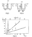
- Fig. 5 die Dämpfungsspektren zweier unter gleichen Ziehbedingungen ausgezogener Monomodefasern mit unterschiedlichen Materialzusammensetzungen entsprechend Fig. 3 und 4.
- 1 is a graphical representation of the dependence of the Rayleigh scattering losses and the wavelength-independent scattering losses on the pulling force,
- 2 shows a graphic representation of the dependence of the incorporation of OH impurities on the refractive index difference,
- 3 schematically shows the refractive index profile p n of a fluorine-doped single-mode fiber without codoping over its radius r,
- Fig. 4 schematically shows the refractive index profile Δn of a fluorine-doped monomode fiber with Ge0 2 codoping over its radius r and
- F ig. 5 shows the attenuation spectra of two single-mode fibers drawn out under the same drawing conditions with different material compositions corresponding to FIGS. 3 and 4.
Für das Dotierungssystem Ge02/Si02 liegen umfangreiche Daten bezüglich der materialintrinsischen optischen Verluste - insbesondere über die Abhängigkeit von der Dotierungskonzentration und den möglichen Einfluß von Ziehbedingungen - vor. Typische Werte für den Rayleigh-Streuverlustterm α R in unterschiedlichen Fasertypen sind:α R≃0,9 bis 1,0 dB um4/km (Monomode-Faser, ΔCO≃0,3%) αR≃1,1 bis 1,3 dB nm4/km (Gradientenindex-Multimode-Faser, ΔCO≃1,0%) bzw.For the doping system Ge0 2 / Si0 2 , extensive data are available regarding the material-intrinsic optical losses - in particular about the dependence on the doping concentration and the possible influence of drawing conditions. Typical values for the Rayleigh scattering loss term α R in different fiber types are: α R≃0.9 to 1.0 dB around 4 / km (monomode fiber, Δ CO ≃0.3%) α R ≃1.1 to 1 .3 dB nm 4 / k m (gradient index multimode fiber, Δ CO ≃1.0%) or
αR ≃1,5 bis 1,7 dB µm4/km (Multimode-Faser mit hoher Apertur, ΔCO≃2,0%). ΔCO ist dabei der relative, maximale Brechungsindexunterschied zwischen Kern- und Mantelmaterial der Lichtleitfaser. Die Rayleigh-Streuverluste sind in diesem Materialsystem weitgehend unabhängig von den Ziehbedingungen, vom Herstellungsverfahren und ebenfalls von gegebenenfalls verwendeten, geringen Mengen an Codotierungen (wie z.B. C2F6); Resteinflüsse sind in den o.a. Daten bereits enthalten. Wellenlängenunabhängige optische Streuverluste (c-Terme) lassen sich bei optimierter Herstellungs- und Ziehprozeßführung in diesem Materialsystem für alle oben angeführten Fasertypen vernachlässigbar klein - d.h. typischerweise kleiner als 0,1 dB/km - halten.α R ≃1.5 to 1.7 dB µm 4 / km (multimode fiber with high aperture, Δ CO ≃2.0%). Δ CO is the relative, maximum difference in refractive index between the core and cladding material of the optical fiber. The Rayleigh scattering losses in this material system are largely independent of the drawing conditions, the manufacturing process and also any small amounts of codoping used (such as C 2 F 6 ); Residual influences are already included in the above data. Wavelength independent optical scattering losses (c-terms) can be iehprozeßführung in this material system for all the above mentioned types of fibers negligibly small with optimized production and Z - that is, typically less than 0.1 dB / km - hold.
Zu berücksichtigen ist somit hauptsächlich die reine materialintrinsische, in erster Näherung lineare Abhängigkeit des Rayleigh-Terms αR von der Dotierungskonzentration. Bei der PCVD-Abscheidung führt dabei ein Anteil von 15 mol% GeC14 im totalen Chloridgasfluß zu einer relativen Brechungsindexerhöhung ΔCO von etwa 1% und einem Rayleigh-Streuterm von etwa 1,1 bis 1,3 dB.pm4/km; die Extrapolation auf den Fall einer reinen Si02-Abscheidung liefert einen intrinsischen Rayleigh-Streuverlustterm von α R(SiO2)≃0,7 bis 0,8 dB.µzm4/km.Mainly the pure material intrinsic, in a first approximation linear dependence of the Rayleigh term α R on the doping concentration has to be considered. In the PCVD deposition in producing a share of 15 mol% GeC1 4 leads total Chloridgasfluß to a relative refractive index Δ CO increase of about 1% and a Rayleigh scattering term of about 1.1 to 1.3 dB.pm 4 / km; extrapolation to the case of pure Si0 2 deposition provides an intrinsic Rayleigh scattering loss term of α R (SiO 2 ) ≃0.7 to 0.8 dB.µzm 4 / km.
Zu erwarten war demzufolge, daß die ausschließliche Verwendung fluorhaltiger Verbindungen als Dotierungsmittel bei der PCVD-Abscheidung - wegen der Möglichkeit, im zentralen Leitungsbereich weitestgehend reines Si02 abzuscheiden - im Vergleich zum Ge02/Si02-Materialsystem zu deutlich niedrigeren optischen Verlusten führen sollte. Wie Fig. 1 zeigt, konnte dieses Verhalten für rein fluordotierte Profilstrukturen jedoch auf experimenteller Basis nicht bestätigt werden: Im Vergleich zu den Daten für das Ge02/Si02-System wurden für rein fluordotierte Lichtleitfasern deutlich höhere Werte für Rayleigh-Streuung α R und c-Term gefunden, die außerdem eine ausgeprägte Abhängigkeit von der Ziehkraft FZ (gemessen in Newton = N) aufweisen. Bei (gegenüber den optimalen Ziehbedingungen für das Ge02/Si02-Materialsystem) unveränderten Ziehbedingungen betragen die entsprechenden optischen Daten für ein hochdotiertes F/Si02-Materialsystem etwa αR ≃2,5 dB.um4/km und c≃0,8 dB/km (ΔCO≃2%, vgl. Fig. 1, Kurve 1: Rayleigh-Streuung, Kurve 2: c-Term). Eine Optimierung des Ziehprozesses in Richtung auf eine gleichzeitige Verringerung beider Verlustterme ist entsprechend Fig. 1, Kurven 1 und 2, in diesem Materialsystem nicht möglich.It was therefore to be expected that the exclusive use of fluorine-containing compounds as dopants in PCVD deposition - because of the possibility of separating largely pure Si0 2 in the central line area - should lead to significantly lower optical losses compared to the Ge0 2 / Si0 2 material system. As Fig. 1 shows, this behavior could not be confirmed on an experimental basis for purely fluorine-doped profile structures: Compared to the data for the Ge0 2 / Si0 2 system, significantly higher values for Rayleigh scattering α R and were found for purely fluorine-doped optical fibers c-Term found, which also have a pronounced dependence on the pulling force F Z (measured in Newton = N). With unchanged drawing conditions (compared to the optimal drawing conditions for the Ge0 2 / Si0 2 material system), the corresponding optical data for a highly doped F / Si0 2 material system are approximately α R ≃2.5 dB.um4 / km and c≃0.8 dB / km (Δ CO ≃2%, see Fig. 1, curve 1: Rayleigh scatter, curve 2: c-term). An optimization of the drawing process in the direction of a simultaneous reduction of both loss terms is not possible in accordance with FIG. 1, curves 1 and 2, in this material system.
Setzt man jedoch bei der Abscheidung stark fluordotierten Materials der Gasphase geringe Mengen von GeCl4 zu (Ge02-Codotierung im Si02/F-System), werden überraschenderweise sowohl die Absolutwerte für Rayleigh- und c-Terme, als auch deren Abhängigkeit von der Ziehkraft deutlich reduziert; unter Standard-Ziehbedingungen betragen die entsprechenden Daten für das mit Ge02 codotierte Si02/F-Materialsystem nur noch αR≃1,0 dB.pm4/km und c≃0,6 dB/km (ΔCO = 2%; vgl. Fig. 1, Kurve 3: Rayleigh-Streuung, Kurve 4: c-Term). Die auch hier vorhandene geringe Restabhängigkeit beider optischer Verlustterme von den Ziehbedingungen läßt jedoch entsprechend Fig. 1, Kurven 3 und 4 - im Gegensatz zum reinen Si02/F-System - eine weitere, erfolgreiche Optimierung der Ziehbedingungen durchaus zu. Insbesondere die Rayleigh-Streuterme liegen für das hoch fluordotierte und gleichzeitig Ge02-codotierte Materialsystem sehr deutlich unter denen der reinen Si02/F- und Si02/Ge02-Dotierungssysteme; darüber hinaus werden in diesem Materialsystem - bei maximalen, relativen Brechungsindexdifferenzen zwischen Kern- und umgebendem Mantelmaterial von ΔCO = 2% - bereits Rayleigh-Streuverluste in der Nähe der für reines Si02 erwarteten Werte erreicht. Zur Erreichung dieser verbesserten optischen Daten genügen bei Anwendung der Erfindung relative Anteile von GeCl4 in der Gasphase von typischerweise 1 bis 4 mol% (bezogen auf die totalen Chloridgasflüsse).However, if small amounts of GeCl 4 are added to the deposition of heavily fluorine-doped material in the gas phase (Ge0 2 codoping in the Si0 2 / F system), surprisingly both the absolute values for Rayleigh and c terms, as well as their dependence on the Pulling force significantly reduced; under standard drawing conditions, the corresponding data for the Si0 2 / F material system coded with Ge0 2 is only α R ≃1.0 d B .pm 4 / km and c≃0.6 dB / km (Δ CO = 2% ; see Fig. 1, curve 3: Rayleigh scattering, curve 4: c-term). However, the low residual dependence of both optical loss terms on the drawing conditions, which is shown in FIG. 1, curves 3 and 4 - in contrast to the pure Si0 2 / F system - also allows a further, successful optimization of the drawing conditions. In particular, the Rayleigh scattering terms for the highly fluorine-doped and at the same time Ge0 2 -codoped material system lie very clearly below those of the pure Si0 2 / F and Si0 2 / Ge0 2 doping systems; In addition, Rayleigh scattering losses in the vicinity of the values expected for pure Si0 2 are already achieved in this material system - with maximum, relative refractive index differences between core and surrounding cladding material of Δ CO = 2%. To achieve these improved optical data, relative proportions of GeCl 4 in the gas phase of typically 1 to 4 mol% (based on the total chloride gas flows ) are sufficient when the invention is used.
Es zeigte sich darüber hinaus, daß eine Ge02-Codotierung überraschenderweise nicht nur die beschriebenen Verbesserungen bewirkt, sondern gleichzeitig den Einbau von OH-Verunreinigungen während der Abscheidung reduziert. Dieses günstige Verhalten ist insbesondere bei hohen Fluordotierungen - z.B. bei C2F6-Konzentrationen von ![]()
![]()
![]()
![]()
Die erfindungsgemäße Codotierung verbessert demzufolge die optischen Eigenschaften fluordotierter Lichtleitfasern, insbesondere in bezug auf Reduzierung von negativen Zieheinflüssen, Verringerung der Beiträge von Rayleigh-Streuung, wellenlängenunabhängigen Streuverlusten und Zusatzabsorptionsverlusten durch OH-Verunreinigungen. Überraschenderweise wird außerdem die Rißbildung in den kollabierten Vorformen weitgehend unterdrückt. Die positive Wirkung ist zudem unabhängig von der speziellen Profilstruktur der hergestellten Lichtleitfasern, d.h. die optischen Eigenschaften werden bei der Herstellung von fluordotierten Multimode- und Monomode-Fasern gleichermaßen verbessert. Die Herstellung von Lichtleitfasern mit unterschiedlichen Profilstrukturen wird anhand einiger Ausführungsbeispiele verdeutlicht.The codoping according to the invention consequently improves the optical properties of fluorine-doped optical fibers, in particular with regard to reducing negative pulling influences, reducing the contributions of Rayleigh scattering, wavelength-independent scattering losses and additional absorption losses due to OH impurities. Surprisingly, the cracking in the collapsed preforms is largely suppressed. The positive effect is also independent of the special profile structure of the optical fibers produced, i.e. the optical properties are improved equally in the production of fluorine-doped multimode and monomode fibers. The production of optical fibers with different profile structures is illustrated using a few exemplary embodiments.
Beispiele 1 und 2: Gradientenindex-Multimode-Fasern Es wurden hoch fluordotierte Gradientenindex-Multimode-Vorformen nach dem PCVD-Verfahren hergestellt, unter unterschiedlichen Ziehbedingungen zu Fasern ausgezogen und anschließend bezüglich ihrer optischen Verluste vermessen. Bis auf die relative Zusammensetzung der Gasphase wurden bei allen Experimenten die PCVD-Abscheidungsparameter konstant gehalten; die Ausführungsbeispiele unterscheiden sich lediglich dadurch, daß beim Beispiel 1 rein fluordotiertes Si02 abgeschieden wurde, wogegen beim Beispiel 2 der Gasphase geringe Mengen von GeC14 als reaktive Zusatzsubstanz zugegeben wurden. Die PCVD-Abscheidung erfolgte in beiden Fällen unter folgenden Versuchsbedingungen:
- Verwendet wurden Si02-Substratrohre mit einem Innendurchmesser von 15 mm und einem Außendurchmesser von 18 mm, die über einer Länge von etwa 45 cm beschichtet wurden. Dabei betrug der Druck im Abscheidungsbereich etwa 20 hPa, die Substrattemperatur etwa 1200 bis 1250°C, die Mikrowellenleistung 750 Watt und die Hubgeschwindigkeit des Resonators über dem Substratrohr 8 m/min. Insgesamt wurden 2000 individuelle Lagen abgeschieden, was einer totalen Beschichtungsdauer von etwa 120 min entsprach.
- Si0 2 substrate tubes with an inner diameter of 15 mm and an outer diameter of 18 mm were used, which were coated over a length of about 45 cm. The pressure in the deposition area was about 20 hPa, the substrate temperature was about 1200 to 1250 ° C., the microwave power was 750 watts and the lifting speed of the resonator above the substrate tube was 8 m / min. A total of 2000 individual layers were deposited, which corresponded to a total coating time of approximately 120 minutes.
Die Reaktionsgasflüsse 6 wurden wie folgt vorgegeben: Während der gesamten Abscheidedauer blieben der Sauerstoff- und der SiC14-Fluß mit Q02 = 800 cm3/min bzw. QSiCl4 = 100 cm3/min konstant. Die Volumenangaben sind auf Normalbedingungen (0°C, 1000 hPa) bezogen. Zur Einstellung des gewünschten Gradientenindexprofils durch eine Fluordotierung wurde der entsprechende Fluß des fluorhaltigen, reaktiven Gases C2F6 während der Abscheidung des optischen Mantelbereichs mit QC2F6 = 15 cm3/min über einen Zeitraum von etwa 60 min konstant gehalten und anschließend - bei der Abscheidung des optischen Kernbereichs - über weitere 60 min (- 1000 Lagen) von 15 cm3/min auf 0,8 cm3/min reduziert. Die Variation von QC2F6 im Kernbereich wurde dabei so vorgenommen, daß in der endgültigen Vorform ein parabolisches Brechungsindexprofil mit einer maximalen, relativen Brechungsindexdifferenz von ΔCO≃2% erzielt wurde. Unter den vorgegebenen Flußbedingungen betrug die maximale C2F6-Konzentration in der Chloridgasphase somit etwa 13 mol% und die mittlere Abscheiderate etwa 0,3 g/min.The reaction gas flows 6 were specified as follows: During the entire deposition period, the oxygen and SiC1 4 flows remained constant with Q 02 = 800 cm 3 / min and Q SiCl4 = 100 cm 3 / min. The volume data are based on normal conditions (0 ° C, 1000 hPa). To set the desired gradient index profile by means of fluorine doping, the corresponding flow of the fluorine-containing, reactive gas C 2 F 6 was kept constant during the deposition of the optical cladding area with Q C2F6 = 15 cm 3 / min over a period of about 60 min and then - at Separation of the optical core area - reduced from 15 cm 3 / min to 0.8 cm 3 / min over a further 60 min (- 1000 layers). The variation of Q C2F6 in the core area was carried out so that a parabolic refractive index profile with a maximum, relative refractive index difference of Δ CO ≃2% was achieved in the final preform. Under the specified flow conditions, the maximum C 2 F 6 concentration in the chloride gas phase was thus about 13 mol% and the average deposition rate was about 0.3 g / min.
Die ohne Verwendung von Ge02-Codotierung mit dem PCVD-Verfahren hergestellten Vorformen wurden mit unterschiedlichen Ziehbedingungen zu Fasern ausgezogen und optisch vermessen: Ein Ausziehen mit 10 m/min bei einer Ofentemperatur von 2100°C (Ziehkraft FZ≃0,08N) führte dabei zu Rayleigh-Streuverlusten von 1,5 dB.pm4/km und c-Term-Verlusten von 2,5 dB/km; eine Ziehgeschwindigkeit von 20 m/min bei einer Ziehtemperatur von etwa 2000°C (Ziehkraft FZ≃0,46N) resultierte in einer Änderung der entsprechenden optischen Streuverlustterme auf Werte von 2,5 dB.pm4/km bzw. 0,5 dB/km. Die Absorptionsverlustanteile durch OH-Verunreinigungen betrugen in beiden Fällen zwischen 10 bis 15 dB/km bei 1,38 pm.The preforms produced without the use of Ge0 2 codoping with the PCVD process were drawn out into fibers with different drawing conditions and measured optically: Pulling out at 10 m / min at an oven temperature of 2100 ° C (drawing force F Z ≃0.08N) resulted thereby to Rayleigh scatter losses of 1.5 dB.pm 4 / km and c-term losses of 2.5 dB / km; a drawing speed of 20 m / min at a drawing temperature of about 2000 ° C (drawing force F Z F0.46N) resulted in a change in the corresponding optical scattering loss terms to values of 2.5 dB.pm 4 / km or 0.5 dB / km. The absorption loss due to OH contamination was between 10 to 15 dB / km at 1.38 pm in both cases.
Das Zufügen eines GeC14-Gasflußanteils von etwa 2,5 mol% im totalen Chloridgasfluß (QGeCl4 = 3,0 cm3/min) während der gesamten PCVD-Abscheidungszeit führte zu folgender Änderung der Streuverlustterme bei unterschiedlichen Ziehbedingungen: Bei 20 m/min Ziehgeschwindigkeit und einer Ziehtemperatur von 2050°C (Standard-Ziehbedingungen für das Si02/Ge02-Materialsystem; entsprechend Ziehkraft etwa 0,3N) betrug der Rayleigh-StreuverlustThe addition of a GeC1 4 gas flow fraction of about 2.5 mol% in the total chloride gas flow (Q GeCl4 = 3.0 cm 3 / min) during the entire PCVD deposition time led to the following change in the leakage loss under different drawing conditions: at 20 m / min Drawing speed and a drawing temperature of 2050 ° C (standard drawing conditions for the Si0 2 / Ge0 2 material system; corresponding to the drawing force about 0.3N) was the Rayleigh scattering loss
1,0 dB.µm4/km und der c-Term-Verlust etwa 0,6 dB/km; bei 40 m/min und 2000°C Ziehtemperatur erhöhten sich diese Werte auf 1,2 dB.pm4/km und 1,0 dB/km. Die zusätzlichen Absorptionsverluste durch OH-Verunreinigungen reduzieren sich in beiden Fällen auf Werte von 4 bis 5 dB/km bei 1,38 um. Die Ge02-Codotierung führte zu einer Reduktion der relativen, maximalen Brechungsindexdifferenz zwischen Kern und Mantel von 2% auf 1,8 bis 1,9%.1.0 dB.µm 4 / km and the c-term loss about 0.6 dB / km; at 40 m / min and 2000 ° C drawing temperature these values increased to 1.2 dB.pm 4 / km and 1.0 dB / km. The additional absorption losses due to OH impurities are reduced in both cases to values of 4 to 5 dB / km at 1.38 µm. The Ge0 2 codoping led to a reduction in the relative, maximum refractive index difference between the core and the cladding from 2% to 1.8 to 1.9%.
Unter den gleichen Abscheidebedingungen wie in den Beispielen 1 und 2 wurden Monomode-Fasern mit den in den Fig. 3 und 4 schematisch dargestellten Brechungsindexprofilen hergestellt.Monomode fibers with the refractive index profiles shown schematically in FIGS. 3 and 4 were produced under the same deposition conditions as in Examples 1 and 2.
Folgende Mischungsverhältnisse wurden beim Abscheideprozeß eingehalten:
- Beispiel 3 (Fig. 3): Für die Kernzone wurden, bezogen auf SiCl4, 0,35 mol% C2F6 zugesetzt. Für die Mantelzone wurden, bezogen auf SiCl4, 1,72 mol% C2F6 zugesetzt.
- Beispiel 4 (Fig. 4): Für die Kernzone wurden, bezogen auf SiCl4, 0,35 mol% C2F6 und 2,65 mol% GeC14 zugesetzt. Für die Mantelzone wurden, bezogen auf SiC14, 1,25 mol% C2F6 und ebenfalls 2,65 mol% GeCl4 zugegeben.
- Example 3 (FIG. 3): For the core zone, based on SiCl 4 , 0.35 mol% of C 2 F 6 were added. For the jacket zone, based on SiCl 4 , 1.72 mol% of C 2 F 6 were added.
- Example 4 (FIG. 4): For the core zone, based on SiCl 4 , 0.35 mol% C 2 F 6 and 2.65 mol% GeC1 4 were added. For the jacket zone, based on SiC1 4 , 1.25 mol% C 2 F 6 and also 2.65 mol% GeCl 4 were added.
Die Brechungsindexprofile beider Faser-Vorformen sind weitgehend identisch. Aus beiden Vorformen wurden unter gleichen Bedingungen Fasern gezogen und bezüglich ihrer optischen Verluste charakterisiert. Die Faser nach Beispiel 3 zeigt einen hohen Rayleigh-Streuterm von 3,15 dB.pm4/km, die nach dem erfindungsgemäßen Verfahren (Beispiel 4) hergestellte Faser, bei der das abgeschiedene Material durch das zudotierte Ge02 einen höheren Ausdehnungskoeffizienten als der umgebende Mantel aufweist, hat dagegen einen niedrigen Rayleigh-Streuterm von 1,14 dB.pm4/km.The refractive index profiles of both fiber preforms are largely identical. Fibers were drawn from both preforms under the same conditions and characterized for their optical losses. The fiber according to Example 3 shows a high Rayleigh scattering term of 3.15 dB.pm 4 / km, the fiber produced by the process according to the invention (example 4), in which the deposited material has a higher expansion coefficient than the surrounding jacket due to the Ge0 2 added , has a low Rayleigh scattering term of 1 , 14 dB.pm 4 / km.
Die zusätzlichen Absorptionsverluste durch OH-Verunreinigungen liegen in beiden Fällen mit etwa 4 dB/km bei 1,38 µm in gleicher Größenordnung. Dies zeigt Fig. 5, in der die Dämpfung α über der Wellenlänge λ bzw. (am oberen Rand) gegen λ -4 aufgetragen ist. In der letztgenannten Darstellung kommt das ( A -4)-Verhalten der Rayleigh-Streuung besonders gut zum Ausdruck. Kurve 7 zeigt das Dämpfungsspektrum der Faser nach Beispiel 3, Kurve 8 das der Faser nach Beispiel 4. Die Gebiete der jeweiligen Grenzwellenlängen sind mit 9 bezeichnet. Die Grenzwellenlänge ("cutoff wavelength") ist definiert als die Wellenlänge, oberhalb der nur noch die Grundmode LP01 geführt wird.In both cases, the additional absorption losses due to OH impurities are approximately 4 dB / km at 1.38 µm in the same order of magnitude. This is shown in FIG. 5, in which the attenuation α is plotted against λ- 4 over the wavelength λ or (at the upper edge). The (A -4 ) behavior of the Rayleigh scattering is particularly well expressed in the latter representation. Curve 7 shows the attenuation spectrum of the fiber according to Example 3,
Claims (6)
dadurch gekennzeichnet, daß sie als Substanz, die den thermischen Ausdehnungskoeffizienten erhöht, Germaniumdioxid enthält.2. Optical fiber according to claim 1,
characterized in that it contains germanium dioxide as a substance which increases the coefficient of thermal expansion.
dadurch gekennzeichnet, daß der Gehalt an der den thermischen Ausdehnungskoeffizienten erhöhenden Substanz 0,3 bis 3,0 mol% beträgt.3. Optical fiber according to claim 1 or 2,
characterized in that the content of the substance which increases the coefficient of thermal expansion is 0.3 to 3.0 mol%.
dadurch gekennzeichnet, daß dem Reaktionsgasgemisch zumindest während der Abscheidung des optischen Leitungsbereichs eine gleichbleibende Menge mindestens einer reaktiven Zusatzsubstanz beigefügt wird, deren Reaktionsprodukt den thermischen Ausdehnungskoeffizienten des abgeschiedenen Materials erhöht.4. A method for producing the optical fiber according to claim 1, 2 or 3, wherein a preform is produced by reactive deposition of silicon dioxide and dopants from a reaction gas mixture, which is further processed into the optical fiber,
characterized in that a constant amount of at least one reactive additive is added to the reaction gas mixture at least during the deposition of the optical line region, the reaction product of which increases the coefficient of thermal expansion of the deposited material.
dadurch gekennzeichnet, daß der Gehalt an Zusatzsubstanz in der reaktiven Gasphase so gewählt wird, daß die Konzentration des Reaktionsprodukts der Zusatzsubstanz im abgeschiedenen Material 0,5 bis 3,0 mol% beträgt.5. The method according to claim 4,
characterized in that the content of additional substance in the reactive gas phase is selected so that the concentration of the reaction product of the additional substance in the deposited material is 0.5 to 3.0 mol%.
dadurch gekennzeichnet, daß bei der reaktiven Abscheidung direkt kompakte Glasschichten ohne Sintern erzeugt werden.6. The method according to claim 4 or 5,
characterized in that the reactive deposition directly produces compact glass layers without sintering.
Applications Claiming Priority (2)
| Application Number | Priority Date | Filing Date | Title |
|---|---|---|---|
| DE3500672 | 1985-01-11 | ||
| DE19853500672 DE3500672A1 (en) | 1985-01-11 | 1985-01-11 | LIGHT-GUIDE FIBER WITH FLUOROUS DOPING AND METHOD FOR THE PRODUCTION THEREOF |
Publications (3)
| Publication Number | Publication Date |
|---|---|
| EP0191202A2 true EP0191202A2 (en) | 1986-08-20 |
| EP0191202A3 EP0191202A3 (en) | 1988-06-01 |
| EP0191202B1 EP0191202B1 (en) | 1990-04-04 |
Family
ID=6259584
Family Applications (1)
| Application Number | Title | Priority Date | Filing Date |
|---|---|---|---|
| EP85202113A Expired - Lifetime EP0191202B1 (en) | 1985-01-11 | 1985-12-19 | Optical fibres doped with fluorine and process for their production |
Country Status (5)
| Country | Link |
|---|---|
| US (1) | US4802733A (en) |
| EP (1) | EP0191202B1 (en) |
| JP (1) | JPS61166503A (en) |
| CN (1) | CN1019384B (en) |
| DE (2) | DE3500672A1 (en) |
Cited By (2)
| Publication number | Priority date | Publication date | Assignee | Title |
|---|---|---|---|---|
| EP0411527A1 (en) * | 1989-08-02 | 1991-02-06 | Alcatel Fibres Optiques | Process for producing an optical fibre with a doped cladding |
| EP0520337A1 (en) * | 1991-06-24 | 1992-12-30 | The Furukawa Electric Co., Ltd. | Optical fiber and process of producing same |
Families Citing this family (21)
| Publication number | Priority date | Publication date | Assignee | Title |
|---|---|---|---|---|
| JPS63208003A (en) * | 1987-02-25 | 1988-08-29 | Sumitomo Electric Ind Ltd | optical fiber |
| KR970000903B1 (en) * | 1989-06-13 | 1997-01-21 | 나카하라 츠네오 | Hermetically coated optical fiber and its manufacturing method |
| US5044724A (en) * | 1989-12-22 | 1991-09-03 | At&T Bell Laboratories | Method of producing optical fiber, and fiber produced by the method |
| US5316795A (en) * | 1990-05-24 | 1994-05-31 | Houston Advanced Research Center | Halogen-assisted chemical vapor deposition of diamond |
| US5071677A (en) * | 1990-05-24 | 1991-12-10 | Houston Advanced Research Center | Halogen-assisted chemical vapor deposition of diamond |
| US5522003A (en) * | 1993-03-02 | 1996-05-28 | Ward; Robert M. | Glass preform with deep radial gradient layer and method of manufacturing same |
| US5613027A (en) | 1994-10-17 | 1997-03-18 | Corning Incorporated | Dispersion shifted optical waveguide fiber |
| WO1999012064A1 (en) * | 1997-08-28 | 1999-03-11 | Sumitomo Electric Industries, Ltd. | Dispersion shift fiber |
| US6556756B2 (en) | 1999-03-17 | 2003-04-29 | Corning Incorporated | Dispersion shifted optical waveguide fiber |
| NL1015405C2 (en) * | 2000-06-09 | 2001-12-12 | Draka Fibre Technology Bv | Single mode optical fiber and method of manufacturing a single mode optical fiber. |
| DE10030264A1 (en) * | 2000-06-20 | 2002-01-03 | Deutsche Telekom Ag | Optical fiber based on quartz glass and method for its production |
| US6574408B2 (en) | 2000-09-14 | 2003-06-03 | Universite De Liege | Monomode optical fibre |
| US6901775B2 (en) * | 2001-09-21 | 2005-06-07 | Corning Incorporated | Method and apparatus for providing a uniform coating thickness along an axial direction within a substrate tube |
| US6771865B2 (en) * | 2002-03-20 | 2004-08-03 | Corning Incorporated | Low bend loss optical fiber and components made therefrom |
| CN1226211C (en) * | 2003-06-27 | 2005-11-09 | 长飞光纤光缆有限公司 | Manufacture of single mode oplical fibers |
| CN100474010C (en) * | 2003-07-18 | 2009-04-01 | 株式会社藤仓 | Graded-index multimode optical fiber and method for manufacturing same |
| NL1024015C2 (en) * | 2003-07-28 | 2005-02-01 | Draka Fibre Technology Bv | Multimode optical fiber provided with a refractive index profile, optical communication system using this and method for manufacturing such a fiber. |
| EP2581770B1 (en) | 2008-02-22 | 2014-05-21 | Sumitomo Electric Industries, Ltd. | Optical fiber and optical cable |
| US8315495B2 (en) * | 2009-01-30 | 2012-11-20 | Corning Incorporated | Large effective area fiber with Ge-free core |
| US7689085B1 (en) | 2009-01-30 | 2010-03-30 | Corning Incorporated | Large effective area fiber with GE-free core |
| EP2518546B1 (en) | 2011-04-27 | 2018-06-20 | Draka Comteq B.V. | High-bandwidth, radiation-resistant multimode optical fiber |
Family Cites Families (17)
| Publication number | Priority date | Publication date | Assignee | Title |
|---|---|---|---|---|
| US3607322A (en) * | 1969-05-22 | 1971-09-21 | Owens Corning Fiberglass Corp | Light transmitting glass fibers, core and cladding glass compositions |
| JPS52121341A (en) * | 1976-04-06 | 1977-10-12 | Nippon Telegr & Teleph Corp <Ntt> | Production of optical fiber base materials and production apparatus fo r the same |
| JPS5395649A (en) * | 1977-02-02 | 1978-08-22 | Hitachi Ltd | Production of optical fiber |
| GB2046239A (en) * | 1979-04-11 | 1980-11-12 | Post Office | Optical fibres |
| CA1124119A (en) * | 1979-10-08 | 1982-05-25 | Katsunari Okamoto | Single mode optical fibers |
| US4425146A (en) * | 1979-12-17 | 1984-01-10 | Nippon Telegraph & Telephone Public Corporation | Method of making glass waveguide for optical circuit |
| FR2476058A1 (en) * | 1980-02-15 | 1981-08-21 | Quartz Silice Sa | SEMI-PRODUCT FOR THE PRODUCTION OF OPTICAL FIBERS, PROCESS FOR PREPARING THE SEMICONDUCTOR AND OPTICAL FIBERS OBTAINED FROM THE SEMICONDUCTOR |
| JPS6022654B2 (en) * | 1980-06-24 | 1985-06-03 | 日本電信電話株式会社 | Manufacturing method of optical communication fiber |
| DE3031147A1 (en) * | 1980-08-18 | 1982-03-18 | Siemens AG, 1000 Berlin und 8000 München | METHOD FOR PRODUCING GLASS WITH A PRE-DETERMINED REFRIGERATION PROFILE AND ALKALINE-FREE GLASS FROM AN OXIS OF A BASE MATERIAL DOPED WITH ONE OR SEVERAL SUBSTANCES |
| FR2496086B1 (en) * | 1980-12-16 | 1985-07-12 | Quartz & Silice | OPTICAL WAVEGUIDE WITH FLUORIC DOPED HEART |
| GB2100464B (en) * | 1981-05-11 | 1985-07-17 | Bicc Plc | An improved optical fibre |
| DE3205345A1 (en) * | 1982-02-15 | 1983-09-01 | Philips Patentverwaltung Gmbh, 2000 Hamburg | "METHOD FOR THE PRODUCTION OF FLUOREDOTED LIGHT-CONDUCTING FIBERS" |
| US4504114A (en) * | 1982-05-10 | 1985-03-12 | Raychem Corporation | Method of transmitting UV light through optical fibers |
| GB2129152B (en) * | 1982-10-30 | 1986-08-13 | Standard Telephones Cables Ltd | Optical fibres |
| US4519826A (en) * | 1983-04-14 | 1985-05-28 | The United States Of America As Represented By The Secretary Of The Navy | Optical fibers having a fluoride glass cladding and method of making |
| DE3318589A1 (en) * | 1983-05-21 | 1984-11-22 | Philips Patentverwaltung Gmbh, 2000 Hamburg | METHOD FOR PRODUCING OPTICAL WAVE GUIDES |
| US4586943A (en) * | 1983-10-20 | 1986-05-06 | Sumitomo Electric Industries, Ltd. | Method for the production of glass preform for optical fibers |
-
1985
- 1985-01-11 DE DE19853500672 patent/DE3500672A1/en not_active Withdrawn
- 1985-12-19 EP EP85202113A patent/EP0191202B1/en not_active Expired - Lifetime
- 1985-12-19 DE DE8585202113T patent/DE3576950D1/en not_active Expired - Lifetime
- 1985-12-30 US US06/814,842 patent/US4802733A/en not_active Expired - Lifetime
-
1986
- 1986-01-08 CN CN86100041A patent/CN1019384B/en not_active Expired
- 1986-01-11 JP JP61002903A patent/JPS61166503A/en active Pending
Cited By (5)
| Publication number | Priority date | Publication date | Assignee | Title |
|---|---|---|---|---|
| EP0411527A1 (en) * | 1989-08-02 | 1991-02-06 | Alcatel Fibres Optiques | Process for producing an optical fibre with a doped cladding |
| FR2650584A1 (en) * | 1989-08-02 | 1991-02-08 | Comp Generale Electricite | METHOD FOR MANUFACTURING OPTICAL FIBER WITH DOPED SHEATH |
| US5090979A (en) * | 1989-08-02 | 1992-02-25 | Compagnie Generale D'electricite | Method of manufacturing an optical fiber preform having doped cladding |
| EP0520337A1 (en) * | 1991-06-24 | 1992-12-30 | The Furukawa Electric Co., Ltd. | Optical fiber and process of producing same |
| US5210816A (en) * | 1991-06-24 | 1993-05-11 | The Furukawa Electric Co., Ltd. | Optical fiber and process of producing same |
Also Published As
| Publication number | Publication date |
|---|---|
| CN86100041A (en) | 1986-07-09 |
| DE3500672A1 (en) | 1986-07-17 |
| CN1019384B (en) | 1992-12-09 |
| JPS61166503A (en) | 1986-07-28 |
| EP0191202B1 (en) | 1990-04-04 |
| DE3576950D1 (en) | 1990-05-10 |
| US4802733A (en) | 1989-02-07 |
| EP0191202A3 (en) | 1988-06-01 |
Similar Documents
| Publication | Publication Date | Title |
|---|---|---|
| EP0191202B1 (en) | Optical fibres doped with fluorine and process for their production | |
| EP0086533B1 (en) | Method of making fluordoped optical fibres | |
| DE2930398C2 (en) | ||
| EP1000909B1 (en) | Process for producing a preform for an optical fibre and a substrate tube suitable for use in the process | |
| DE3105295C2 (en) | ||
| DE69017397T2 (en) | Method of manufacturing an optical fiber and fiber made by this method. | |
| EP0309027A1 (en) | Method of manufacturing a monomode optical fibre | |
| EP0341427A2 (en) | Single mode light-guiding fibre, and method for its production | |
| DE10152328B4 (en) | Process for producing a tube made of quartz glass, tubular semi-finished product made of porous quartz glass and. Use of the same | |
| EP1286926A1 (en) | Method for producing an optical fibre | |
| DE2642949A1 (en) | Process for the production of internally coated glass tubes for the drawing of optical fibers | |
| DE2930816C2 (en) | Optical fiber with a cladding glass, mainly made of quartz glass, and a core glass made of quartz glass, doped with Ge0? 2? and P? 2? 0? 5?, Ti0? 2?, Al? 2? 0? 3? and / or Ga? 2? 0? 3? | |
| DE69323980T2 (en) | Process for the production of preforms for optical waveguides | |
| DE60209457T2 (en) | Doped core and cladding optical fiber, cladding, preform and method of making such a fiber | |
| WO2001040126A1 (en) | Quartz glass blank for a light-conducting fiber and a method for production of said blank | |
| EP0127227B1 (en) | Method of manufacturing optical wave guides | |
| DE60200189T2 (en) | Process for producing optical fibers from preforms by regulating the partial pressure of oxygen during dehydration of the preform | |
| EP0295745B1 (en) | Method for making optical fibers | |
| DE69032175T2 (en) | Method and device for producing a preform with a doped metal oxide | |
| DE3635819C2 (en) | ||
| DE10027263B4 (en) | A method of making an SiO2-based optical fiber for transmitting a high power density | |
| EP0536631B1 (en) | Method for making a preform for optical fibers | |
| EP0100998B1 (en) | Method of making a glass fibre with a radial refraction profile | |
| DE2938218C2 (en) | Method of making a glass object | |
| EP0208086A1 (en) | Method for producing fluorine-doped silicia glass preforms for drawing glass fibres for optical telecommunication |
Legal Events
| Date | Code | Title | Description |
|---|---|---|---|
| PUAI | Public reference made under article 153(3) epc to a published international application that has entered the european phase |
Free format text: ORIGINAL CODE: 0009012 |
|
| AK | Designated contracting states |
Kind code of ref document: A2 Designated state(s): DE FR GB IT NL SE |
|
| RAP1 | Party data changed (applicant data changed or rights of an application transferred) |
Owner name: N.V. PHILIPS' GLOEILAMPENFABRIEKEN Owner name: PHILIPS PATENTVERWALTUNG GMBH |
|
| PUAL | Search report despatched |
Free format text: ORIGINAL CODE: 0009013 |
|
| AK | Designated contracting states |
Kind code of ref document: A3 Designated state(s): DE FR GB IT NL SE |
|
| 17P | Request for examination filed |
Effective date: 19881124 |
|
| 17Q | First examination report despatched |
Effective date: 19890606 |
|
| GRAA | (expected) grant |
Free format text: ORIGINAL CODE: 0009210 |
|
| AK | Designated contracting states |
Kind code of ref document: B1 Designated state(s): DE FR GB IT NL SE |
|
| REF | Corresponds to: |
Ref document number: 3576950 Country of ref document: DE Date of ref document: 19900510 |
|
| ITF | It: translation for a ep patent filed | ||
| ET | Fr: translation filed | ||
| GBT | Gb: translation of ep patent filed (gb section 77(6)(a)/1977) | ||
| PG25 | Lapsed in a contracting state [announced via postgrant information from national office to epo] |
Ref country code: SE Effective date: 19901220 |
|
| PLBE | No opposition filed within time limit |
Free format text: ORIGINAL CODE: 0009261 |
|
| STAA | Information on the status of an ep patent application or granted ep patent |
Free format text: STATUS: NO OPPOSITION FILED WITHIN TIME LIMIT |
|
| 26N | No opposition filed | ||
| PG25 | Lapsed in a contracting state [announced via postgrant information from national office to epo] |
Ref country code: NL Effective date: 19910701 |
|
| NLV4 | Nl: lapsed or anulled due to non-payment of the annual fee | ||
| ITTA | It: last paid annual fee | ||
| EUG | Se: european patent has lapsed |
Ref document number: 85202113.8 Effective date: 19910910 |
|
| ITPR | It: changes in ownership of a european patent |
Owner name: CAMBIO RAGIONE SOCIALE;PHILIPS ELECTRONICS N.V. |
|
| REG | Reference to a national code |
Ref country code: FR Ref legal event code: CD |
|
| REG | Reference to a national code |
Ref country code: GB Ref legal event code: 732E |
|
| REG | Reference to a national code |
Ref country code: FR Ref legal event code: TP |
|
| REG | Reference to a national code |
Ref country code: GB Ref legal event code: IF02 |
|
| PGFP | Annual fee paid to national office [announced via postgrant information from national office to epo] |
Ref country code: FR Payment date: 20030926 Year of fee payment: 19 |
|
| PGFP | Annual fee paid to national office [announced via postgrant information from national office to epo] |
Ref country code: GB Payment date: 20031217 Year of fee payment: 19 |
|
| PGFP | Annual fee paid to national office [announced via postgrant information from national office to epo] |
Ref country code: DE Payment date: 20031231 Year of fee payment: 19 |
|
| PG25 | Lapsed in a contracting state [announced via postgrant information from national office to epo] |
Ref country code: GB Free format text: LAPSE BECAUSE OF NON-PAYMENT OF DUE FEES Effective date: 20041219 |
|
| PG25 | Lapsed in a contracting state [announced via postgrant information from national office to epo] |
Ref country code: DE Free format text: LAPSE BECAUSE OF NON-PAYMENT OF DUE FEES Effective date: 20050701 |
|
| GBPC | Gb: european patent ceased through non-payment of renewal fee |
Effective date: 20041219 |
|
| PG25 | Lapsed in a contracting state [announced via postgrant information from national office to epo] |
Ref country code: FR Free format text: LAPSE BECAUSE OF NON-PAYMENT OF DUE FEES Effective date: 20050831 |
|
| REG | Reference to a national code |
Ref country code: FR Ref legal event code: ST |