EP0190943B1 - Aircraft engine bleed air flow balancing technique - Google Patents
Aircraft engine bleed air flow balancing technique Download PDFInfo
- Publication number
- EP0190943B1 EP0190943B1 EP19860300849 EP86300849A EP0190943B1 EP 0190943 B1 EP0190943 B1 EP 0190943B1 EP 19860300849 EP19860300849 EP 19860300849 EP 86300849 A EP86300849 A EP 86300849A EP 0190943 B1 EP0190943 B1 EP 0190943B1
- Authority
- EP
- European Patent Office
- Prior art keywords
- bleed air
- pressure
- engine
- signal
- valve
- Prior art date
- Legal status (The legal status is an assumption and is not a legal conclusion. Google has not performed a legal analysis and makes no representation as to the accuracy of the status listed.)
- Expired - Lifetime
Links
Images
Classifications
-
- B—PERFORMING OPERATIONS; TRANSPORTING
- B64—AIRCRAFT; AVIATION; COSMONAUTICS
- B64D—EQUIPMENT FOR FITTING IN OR TO AIRCRAFT; FLIGHT SUITS; PARACHUTES; ARRANGEMENTS OR MOUNTING OF POWER PLANTS OR PROPULSION TRANSMISSIONS IN AIRCRAFT
- B64D13/00—Arrangements or adaptations of air-treatment apparatus for aircraft crew or passengers, or freight space, or structural parts of the aircraft
-
- F—MECHANICAL ENGINEERING; LIGHTING; HEATING; WEAPONS; BLASTING
- F02—COMBUSTION ENGINES; HOT-GAS OR COMBUSTION-PRODUCT ENGINE PLANTS
- F02C—GAS-TURBINE PLANTS; AIR INTAKES FOR JET-PROPULSION PLANTS; CONTROLLING FUEL SUPPLY IN AIR-BREATHING JET-PROPULSION PLANTS
- F02C6/00—Plural gas-turbine plants; Combinations of gas-turbine plants with other apparatus; Adaptations of gas- turbine plants for special use
- F02C6/04—Gas-turbine plants providing heated or pressurised working fluid for other apparatus, e.g. without mechanical power output
- F02C6/06—Gas-turbine plants providing heated or pressurised working fluid for other apparatus, e.g. without mechanical power output providing compressed gas
- F02C6/08—Gas-turbine plants providing heated or pressurised working fluid for other apparatus, e.g. without mechanical power output providing compressed gas the gas being bled from the gas-turbine compressor
-
- F—MECHANICAL ENGINEERING; LIGHTING; HEATING; WEAPONS; BLASTING
- F02—COMBUSTION ENGINES; HOT-GAS OR COMBUSTION-PRODUCT ENGINE PLANTS
- F02C—GAS-TURBINE PLANTS; AIR INTAKES FOR JET-PROPULSION PLANTS; CONTROLLING FUEL SUPPLY IN AIR-BREATHING JET-PROPULSION PLANTS
- F02C9/00—Controlling gas-turbine plants; Controlling fuel supply in air- breathing jet-propulsion plants
- F02C9/16—Control of working fluid flow
- F02C9/18—Control of working fluid flow by bleeding, bypassing or acting on variable working fluid interconnections between turbines or compressors or their stages
-
- G—PHYSICS
- G05—CONTROLLING; REGULATING
- G05D—SYSTEMS FOR CONTROLLING OR REGULATING NON-ELECTRIC VARIABLES
- G05D7/00—Control of flow
- G05D7/03—Control of flow with auxiliary non-electric power
-
- Y—GENERAL TAGGING OF NEW TECHNOLOGICAL DEVELOPMENTS; GENERAL TAGGING OF CROSS-SECTIONAL TECHNOLOGIES SPANNING OVER SEVERAL SECTIONS OF THE IPC; TECHNICAL SUBJECTS COVERED BY FORMER USPC CROSS-REFERENCE ART COLLECTIONS [XRACs] AND DIGESTS
- Y02—TECHNOLOGIES OR APPLICATIONS FOR MITIGATION OR ADAPTATION AGAINST CLIMATE CHANGE
- Y02T—CLIMATE CHANGE MITIGATION TECHNOLOGIES RELATED TO TRANSPORTATION
- Y02T50/00—Aeronautics or air transport
- Y02T50/50—On board measures aiming to increase energy efficiency
-
- Y—GENERAL TAGGING OF NEW TECHNOLOGICAL DEVELOPMENTS; GENERAL TAGGING OF CROSS-SECTIONAL TECHNOLOGIES SPANNING OVER SEVERAL SECTIONS OF THE IPC; TECHNICAL SUBJECTS COVERED BY FORMER USPC CROSS-REFERENCE ART COLLECTIONS [XRACs] AND DIGESTS
- Y10—TECHNICAL SUBJECTS COVERED BY FORMER USPC
- Y10T—TECHNICAL SUBJECTS COVERED BY FORMER US CLASSIFICATION
- Y10T137/00—Fluid handling
- Y10T137/7722—Line condition change responsive valves
- Y10T137/7758—Pilot or servo controlled
- Y10T137/7759—Responsive to change in rate of fluid flow
Definitions
- This invention relates to a bleed air system on aircraft to deliver compressed or bleed air from the power source, typically a turbine engine, to other air systems, requiring a continuous supply of air, such as environmental control systems, and more particularly to a system for controlling bleed air supplied by the engines of multi-engine aircraft in order to ensure a balanced supply of bleed air from each of the engines on the aircraft, thereby achieving balanced flow extraction as specified in the preamble of claims 1 and as disclosed for example in the document GB-A-1 140 181.
- Bleed air control systems have developed some degree of sophistication, and typically utilize a pressure regulating valve to control the amount of bleed air supplied from each engine to a heat exchanger used to cool the bleed air from that engine, with the cooled air from all the engines then being fed into a common manifold prior to distribution on board the aircraft.
- pressure regulation valves are reasonably sophisticated mechanical devices, and as such are susceptible to some degree of mechanical tolerance inherent in the performance characteristics of such valves.
- Pressure regulating valves are designed to regulate bleed air pressure of air supplied from an engine to a heat exchanger, and typically operate with a tolerance of plus or minus 0.175 Kg/cm 2 . While such a tolerance seems relatively good in view of the fact that this represents an error of approximately only plus or minus 4%, it nevertheless does present a potentially highly damaging situation.
- a second and even more expensive result of the problem is an increased level of engine distress.
- the engine required to supply substantially more bleed air will wear out significantly faster, since the blades of the turbine engine will be running hotter due to the increased amount of bleed air, tapped off due to the engine pressure regulating valve supplying air at a higher pressure than the pressure regulating valves of the other engine(s). This results in the requirement that the engine be rebuilt or replaced at a substantially earlier time and after substantially fewer operating hours.
- GB-A-1140181 describes a bleed air system or an aircraft having a plurality of engines including a bleed air valve for controlling the amount of bleed air supplied by an engine.
- a primary valve monitors bleed air pressure downstream of the bleed air valve, the primary valve being arranged to produce a first signal proportional to the bleed air pressure at the first location.
- An actuator drives the bleed air valve to regulate the pressure of bleed air supplied from the engine in response to the first signal.
- An emergency valve monitors bleed air pressure at a second location upstream of the first location, the emergency valve being arranged to produce a second signal proportional to the bleed air pressure at the second location.
- a poppet valve modulates the actuator to maintain a preselected flow of bleed air from the engine, the poppet valve being responsive to the first and second signals.
- a bleed air system for use with an aircraft having a plurality of engines, comprising a bleed air valve for controlling the amount of bleed air supplied by an engine; first means for monitoring bleed air pressure at a first location downstream of the bleed air valve, the first monitoring means being arranged to produce a first signal proportional to bleed air pressure at the first location; means for driving the bleed air valve to regulate the pressure of the bleed air supplied from the engine in response to the first signal; second means for monitoring the bleed air pressure, the second monitoring means being arranged to produce a second signal proportional to the bleed air pressure at the second location; and means for modulating the driving means to maintain a preselected flow of bleed air from the engine, the modulating means being responsive to the first signal and the second signal,characterised in that the second monitoring means is at a second location downstream of the first location.
- a multi-engine bleed air system comprises, for each engine, a bleed air regulating valve and a valve-position controller, characterised in that each valve-position controller is subjected to first and second signals which are respectively proportional to bleed air pressures at first and second locations downstream of the respective valve.
- the present invention thus utilizes a bleed flow modulator in conjunction with each pressure regulating valve to ensure that the pressure regulating valve does not supply more bleed air than desired from the engine regulated by the pressure regulating valve.
- the bleed flow modulator may thus be a pressure differential sensing device which measures a pressure drop across a portion of the normal bleed air delivery equipment prior to supply of the bleed air to the common manifold.
- the bleed flow modulator measures the pressure differential across a heat exchanger which is immediately downstream from the pressure regulating valve.
- the bleed flow modulator Since pressure drop is related to flow volume, the bleed flow modulator thereby senses flow of bleed air through the heat exchanger.
- the bleed flow modulator provides a negative feedback signal to the pressure regulating valve whenever an excessive pressure drop is sensed across the heat exchanger, thereby indicating excessive flow being supplied by the pressure regulating valve.
- This negative feedback signal provided by the bleed flow modulator to the pressure regulating valve causes the pressure regulating valve to close somewhat, thereby reducing the flow through that particular, pressure regulating valve.
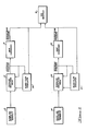
- FIG. 1 illustrates the operation of a system embodying the present invention in a twin-engined aircraft.
- a twin-engined aircraft is used as a specific example herein, it will be recognised by those skilled in the art that the present invention is equally applicable to use on any aircraft having multiple engines from which bleed air is supplied.
- its use on a single leg of the system that is on a single engine, pressure regulating valve, and heat exchanger combination is described.
- the construction and operation of the system on each of the legs of the bleed air supply system in a multi-engine aircraft is identical, and therefore discussion of only a single leg of the system is necessary.
- a bleed air source 1 (which is the first engine of the aircraft) is referred to generally as source 10, and is a source of bleed airflow, the particulars of which are well known in the art.
- the source 10 supplies bleed air to a pressure regulating valve 12, which operates to regulate the pressure of the bleed air supplied to a heat exchanger 14.
- the pressure regulating valve 12 in a typical example will regulate the pressure to 4.06 Kg/cm 2 , and accordingly, bleed air is supplied at 4.06 Kg/cm 2 to the heat exchanger 14, where the bleed air is typically cooled.
- the heat exchanger 14 then supplies the bleed air to an ECS manifold 16, which is a common manifold to which bleed air is supplied from all the engines on the aircraft.
- the second engine of the two engine aircraft used as an example is bleed air source 2, specifically identified as source 18 in Figure 1.
- the source 18 supplies bleed air to a second pressure regulating valve 20, which, in turn, supplies bleed air at approximately 4.06 Kg/cm 2 to a second heat exchanger 22.
- a bleed flow modulator 24 is used in combination with the pressure regulating valve 12 to regulate the flow of bleed air through the heat exchanger 14, and a second bleed flow modulator 26 is used in combination with the second pressure regulating valve 20 to regulate the flow of bleed air through the second heat exchanger 22.
- the pressure regulating valves 12, 20 utilize negative feedback to obtain a relatively accurate pressure regulation of the bleed air flow. Specifically, pressure on the outlet ends of the pressure regulating valves 12, 20 is monitored by the pressure regulating valves 12, 20, this pressure value, in each case, being designated the upstream pressure in Figure 1, and corresponding to the pressure of the bleed air as supplied to the heat exchangers 14, 22.
- the bleed air flow modulators 24, 26 each operate as a function of both upstream pressure, i.e. the pressure of bleed air supplied to the heat respective exchanger 14, 22, and downstream pressure, which is the pressure of bleed air exiting the respective heat exchangers 14 and 22.
- the bleed flow modulators 24, 26 provide feedback signals to the pressure regulating valves 12, 20, respectively, in order to balance the flows supplied by the heat exchangers 14, 22 to the ECS manifold 16.
- the operation of the bleed flow modulators 24, 26 is based on a mathematical relationship between pressure drop across the heat exchangers 14, 22 and the flow through the heat exchangers 14, 22.
- Pressure Drop f times w 2 , where Pressure Drop is the pressure differential across a heat exchanger, w is flow through the heat exchanger, and f is a constant based on density of the bleed air and the particular mechanical design of the heat exchanger. From this formula it is apparent that flow of bleed air through the heat exchangers 14, 22 is directly dependent upon the pressure drop across the heat exchangers 14, 22. Therefore, if the pressure drops across the heat exchangers are regulated, the result will be that the flow from the two heat exchangers 14, 22 will be balanced to cause the extraction of bleed air from sources 10, 18 to be identical.
- the bleed flow modulators 24, 26 monitor both upstream pressure and downstream pressure, they may be manufactured and adjusted so as to regulate the system by providing negative feedback to the pressure regulating valves 1, 12, 20 respectively.
- the bleed flow modulators will provide limited authority negative feedback signals to the pressure regulating valves 12, 20, respectively, thereby resulting in flow being reduced to a value representing the desired bleed air flow through the heat exchanger 14,22.
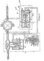
- Figure 2 illustrates the top leg of the system shown in Figure 1, namely that consisting of the pressure regulating valve 12, the heat exchanger 14, and the bleed flow modulator 24.
- the heat exchanger 14 has an inlet 30 to which bleed air is supplied from the pressure regulating valve 12, the bleed air originating from the source 10 ( Figure 1).
- the bleed air is cooled in the heat exchanger 14, and leaves the heat exchanger through an exit 32.
- An additional entrance 34 and exit 36 to the heat exchanger are illustrated, for the flow path of the cooling air used to cool the flow of bleed air in the heat exchanger 14.
- the supply of cooling air to a heat exchanger is well known in the art.
- the pressure regulating valve 12 illustrated in Figure 2 is a spring-loaded-open, pneumatically actuated butterfly type pressure regulating valve.
- a butterfly valve 40 is used selectively to block or allow passage of the bleed air flow through the pressure regulating valve 12.
- the butterfly valve is connected by a mechanical linkage 42 to a piston 44 slidably mounted in a valve housing 46.
- the valve housing 46 is divided into two chambers, namely a chamber A on one side of the piston 44 and chamber B on the opposite side of the piston 44.
- An O-ring 48 is mounted on the piston 44 to provide a seal between chambers A and B, with a second O-ring 50 being utilized to seal the valve housing 46 at the end at which the mechanical linkage 42 is connected to the piston 44.
- a spring 52 is located inside the valve housing 45 and bears against the piston 44 in the chamber B. It is therefore apparent that the pressure in the chamber B, and the pressure exerted by the spring 42 will both operate to cause the piston 44 to move in a direction causing the butterfly valve 40 to be open, while a pressure in chamber A will cause the piston 44 to move in a direction causing the butterfly valve 40 to close.
- a poppet housing 54 contains a diaphragm 56 having a reinforced central portion 58.
- the diaphragm 56 with its reinforced central portion 58, form a chamber C on one side of the poppet housing 54, with the other side being exposed to ambient pressure at location 60.
- Attached to the reinforced central portion 58 of the diaphragm 56 is a rod 62 leading to a poppet 64 installed in a poppet seat 66.
- the poppet 64 is kept in its seat 66 by pressure exerted by a spring 68 bearing at one end on the poppet housing 54 and at the other end on the side of the diaphragm 56 and its reinforced central portion 58 opposite to the chamber C.
- the poppet 64 is urged away from its seat 66 by a spring 70 and pressure C.
- Pressure exerted by the spring 70 on the reinforced central portion 58 of the diaphragm 56 is adjustable by turning an adjustment screw 72, which adjusts the pressure to which the pressure regulating valve will regulate.
- the poppet 64 is located in a portion of the poppet housing 54 having a chamber 74 with three openings leading into it.
- the first of these openings is the poppet seat 66, which leads to ambient pressure at the 16cation 60.
- the second opening to the chamber 74 is a control orifice 76, which is connected to chamber A and to the inlet 30 to the heat exchanger 14, where upstream pressure is sensed. Therefore, upstream pressure will be supplied to chamber A and, through the orifice 76, to the chamber 74.
- the third opening 73 to the chamber 74 leads to chambers B and C. (Connections of the pressure regulating valve 12 to the bleed flow modulator 24 will not be discussed at this point, but later in conjunction with the description of the bleed flow modulator 24).
- the pressure regulating valve 12 may produce a pressure varying by 0.175 Kg/cm 2 from the desired value due to mechanical tolerances, in order to maintain a flow through the heat exchanger 14 which is equal to the flow through other heat exchangers in the aircraft, it is necessary to utilize the bleed flow modulator 24.
- the bleed flow modulator 24 utilizes a diaphragm 80 with a reinforced central portion 82 mounted in a modulator housing 84.
- a chamber D On one side of the diaphragm 80 is a chamber D connected to the inlet 30 to the heat exchanger 14, and therefore upstream pressure will be applied to this side of the diaphragm 80.
- a chamber E On the other side of the diaphragm 80, there is a chamber E connected to the outlet 32 of the heat exchanger 14, and therefore downstream pressure will be supplied to the other side of the diaphragm 80. It may therefore, be appreciated that the pressure drop across the heat exchanger 14 will cause the diaphragm 80 to move as that pressure drop varies. Note also that any pressure drop in the leg supplying bleed air may be used, not just the drop across the heat exchanger.
- an L-shaped valve element 86 which pivots about an axis 85.
- the end 86A of one limb 86B of the valve element 86 acts to regulate the entry of ambient air into a tube 94, to be described.
- the valve element 86 is held in a closed position by a spring 88 acting against the other limb 86C of the valve element.
- the valve element 86 is moved in an opening direction by the diaphragm 80, which has connected to the reinforced central portion 82 a rod 90 which exerts pressure on the limb 86C of the valve element 86, tending to cause the valve element to open.
- a spring 92 exerting pressure on the reinforced central portion 82 of the diaphragm 80, and hence on the valve element 86, is a spring 92, with the net force of the springs 88, 92 holding the valve element 86 closed.
- valve element 86 When the valve element 86 opens, it allows ambient air to enter the small tube 94, which tube 94 has a number of apertures in the walls thereof leading to a chamber 96 contained in the modulator housing 84.
- the valve element 86 When the valve element 86 is moved into an open position by the pressure drop across the heat exchanger 14 reaching a certain value, ambient air is allowed to enter the tube 94, and is thereby supplied to the chamber 96.
- the amount of pressure drop required across the heat exchanger 14 to open the valve element 86 is varied by an adjustment screw 98 which moves the tube 94 into tighter or looser contact with the valve element 86, thereby requiring more or less force, respectively, to open the valve element 86.
- the bleed flow modulator 24 is a device which provides a pneumatic output signal to the chamber 96 which varies inversely with the sensed differential pressure across the heat exchanger 14, and hence the diaphragm 80. Since the differential pressure across the heat exchanger 14 is proportional to the flow through the heat exchanger 14, the bleed flow modulator 24 provides an output signal to chamber 96 that varies inversely with the flow of bleed air through the heat exchanger 14.
- the chamber 96 is connected to chamber B and C of the pressure regulating valve 12. Therefore, if the flow through the heat exchanger 14 increases beyond a desired level, the valve element 86 in the bleed flow modulator 24 will open, causing pressure in chamber B and C in the pressure regulating valve 12 to drop, which in turn causes the butterfly valve 40 to begin to close. The result is a decrease in flow through the heat exchanger 14, and the system illustrated in Figure 2 will come to an equilibrium point whereby the desired airflow rate through the heat exchanger 14 is continuously maintained.
Landscapes
- Engineering & Computer Science (AREA)
- Chemical & Material Sciences (AREA)
- Combustion & Propulsion (AREA)
- General Engineering & Computer Science (AREA)
- Mechanical Engineering (AREA)
- Physics & Mathematics (AREA)
- Aviation & Aerospace Engineering (AREA)
- Fluid Mechanics (AREA)
- Health & Medical Sciences (AREA)
- Pulmonology (AREA)
- General Health & Medical Sciences (AREA)
- Power Engineering (AREA)
- General Physics & Mathematics (AREA)
- Automation & Control Theory (AREA)
- Control Of The Air-Fuel Ratio Of Carburetors (AREA)
- Control Of Fluid Pressure (AREA)
- Respiratory Apparatuses And Protective Means (AREA)
- Percussion Or Vibration Massage (AREA)
Description
- This invention relates to a bleed air system on aircraft to deliver compressed or bleed air from the power source, typically a turbine engine, to other air systems, requiring a continuous supply of air, such as environmental control systems, and more particularly to a system for controlling bleed air supplied by the engines of multi-engine aircraft in order to ensure a balanced supply of bleed air from each of the engines on the aircraft, thereby achieving balanced flow extraction as specified in the preamble of claims 1 and as disclosed for example in the document GB-A-1 140 181.
- With the exception of a limited number of smaller aircraft, most aircraft utilising turbine engine propulsion units, both commercial and military, are powered by two or more turbine engines. Virtually all such aircraft divert bleed air from the engines to supply various other systems, most notably environmental control systems (ECS) which require a supply of conditioned air which is utilized for the crew and passenger environment, and in some instances electronic equipment on board the aircraft is cooled by a portion of the bleed air.
- It has been recognised for quite some time that in order efficiently to operate a multiple engine aircraft it is desirable to utilize bleed air supplied from all of the engines rather than from only one. If, for example, the entire supply of bleed air to the aircraft is supplied by one engine, the result is a significantly deteriorated overall aircraft fuel economy, as well as excessive wear of the engine supplying the bleed air, since that engine also has to carry its share of the aircraft propulsion duties. Bleed air control systems have developed some degree of sophistication, and typically utilize a pressure regulating valve to control the amount of bleed air supplied from each engine to a heat exchanger used to cool the bleed air from that engine, with the cooled air from all the engines then being fed into a common manifold prior to distribution on board the aircraft.
- Aside from this rather significant accomplishment, most effort in the art of bleed air control systems has been directed towards preventing compressor surge in the various stages of the gas turbine engine, by bleeding airflow from appropriate stages during certain flight conditions, with the excess air bled off typically being dumped into the ambient atmosphere. Two examples of such systems are U.S. Patents Nos. 3 179 356 and 3 505 817, both of which are used to prevent back flow into lagging engines, and bleed flow to the atmosphere when there is excessive bleed air to prevent compressor surge. While in most cases acceptable performance has been achieved by existing systems, one significant problem remains in bleed air control systems, with this problem posing significant (and expensive) instances of deteriorated system performance.
- It will be recognised that pressure regulation valves are reasonably sophisticated mechanical devices, and as such are susceptible to some degree of mechanical tolerance inherent in the performance characteristics of such valves. Pressure regulating valves are designed to regulate bleed air pressure of air supplied from an engine to a heat exchanger, and typically operate with a tolerance of plus or minus 0.175 Kg/cm2. While such a tolerance seems relatively good in view of the fact that this represents an error of approximately only plus or minus 4%, it nevertheless does present a potentially highly damaging situation.
- Using by way of an example an aircraft having two engines with both engines supplying bleed air, consider the case when one pressure regulating valve, on the first engine, has an error allowing pressure to be slightly larger than desired, for example 0.14 Kg/cm2 higher than desired, and the second pressure regulating valve on the other engine has an error in the opposite direction so that air leaving the second pressure regulating valve is 0.14 Kg/cm2 below the desired value. In this case, the pressure regulating valve supplying air at the higher pressure will supply significantly more air than the pressure regulating valve supplying air at the lower pressure, which means that one engine is supplying significantly more bleed air than the other engine.
- While the situation described above is serious and has a detrimental effect on overall aircraft performance, an even more serious consequence is likely to occur when the difference in supply pressure is more than minimal. If there is a difference of several psig in air supplied by two pressure regulating valves, as in the example just described, the result can be that the regulating valve operating at the higher pressure will force air backwards in the system in the wrong direction through the regulating valve operating at the lower pressure, a situation which is known as the higher regulator swamping out the lower regulator. When this occurs, one engine will supply all of the bleed air required by the aircraft and the other engine will supply no bleed air at all, since the regulating valves are designed to prevent reverse flow of air therethrough, by closing.
- The results of pressure regulating valve error are present to some degree even with fairly small amounts of error in the pressure regulating valves, with the results of such imbalance increasing in severity with the magnitude of the error. The most immediately noticeable result is substantially diminished aircraft fuel economy, since the engine supplying significantly more bleed air will burn more fuel than the other engine saves. It will be appreciated that such a reduction in fuel economy will have severe economic results, particularly in the case of commercial aircraft.
- A second and even more expensive result of the problem is an increased level of engine distress. The engine required to supply substantially more bleed air will wear out significantly faster, since the blades of the turbine engine will be running hotter due to the increased amount of bleed air, tapped off due to the engine pressure regulating valve supplying air at a higher pressure than the pressure regulating valves of the other engine(s). This results in the requirement that the engine be rebuilt or replaced at a substantially earlier time and after substantially fewer operating hours.
- While the previous discussion has concentrated on the example of a twin engine aircraft, it is apparent that the pressure regulation problem will be at least as severe on aircraft having more than two engines. For example, if a four-engine aircraft has one pressure regulating valve supplying air to a higher pressure than the other three, it is possible for that pressure regulating valve to swamp out the other three regulating valves, thereby requiring a single engine to supply all the bleed air utilized by the aircraft. The results in this case are an unacceptably serious reduction in both fuel economy and engine wear characteristics. It is therefore seen that a system which will ensure more accurate pressure regulation of bleed air is highly desirable since such a system would result both in better aircraft economy and a lower degree of mechanical wear in the engine. Such a system, whether utilized on a two-engine aircraft, or an aircraft having more than two engines, will likely pay for itself in a relatively short operating time, and therefore represents a highly desirable addition to any bleed air control system.
- GB-A-1140181 describes a bleed air system or an aircraft having a plurality of engines including a bleed air valve for controlling the amount of bleed air supplied by an engine. A primary valve monitors bleed air pressure downstream of the bleed air valve, the primary valve being arranged to produce a first signal proportional to the bleed air pressure at the first location. An actuator drives the bleed air valve to regulate the pressure of bleed air supplied from the engine in response to the first signal. An emergency valve monitors bleed air pressure at a second location upstream of the first location, the emergency valve being arranged to produce a second signal proportional to the bleed air pressure at the second location. A poppet valve modulates the actuator to maintain a preselected flow of bleed air from the engine, the poppet valve being responsive to the first and second signals.
- According to the present invention there is provided a bleed air system for use with an aircraft having a plurality of engines, comprising a bleed air valve for controlling the amount of bleed air supplied by an engine; first means for monitoring bleed air pressure at a first location downstream of the bleed air valve, the first monitoring means being arranged to produce a first signal proportional to bleed air pressure at the first location; means for driving the bleed air valve to regulate the pressure of the bleed air supplied from the engine in response to the first signal; second means for monitoring the bleed air pressure, the second monitoring means being arranged to produce a second signal proportional to the bleed air pressure at the second location; and means for modulating the driving means to maintain a preselected flow of bleed air from the engine, the modulating means being responsive to the first signal and the second signal,characterised in that the second monitoring means is at a second location downstream of the first location.
- According to a specific aspect of the present invention a multi-engine bleed air system comprises, for each engine, a bleed air regulating valve and a valve-position controller, characterised in that each valve-position controller is subjected to first and second signals which are respectively proportional to bleed air pressures at first and second locations downstream of the respective valve.
- The present invention thus utilizes a bleed flow modulator in conjunction with each pressure regulating valve to ensure that the pressure regulating valve does not supply more bleed air than desired from the engine regulated by the pressure regulating valve. The bleed flow modulator may thus be a pressure differential sensing device which measures a pressure drop across a portion of the normal bleed air delivery equipment prior to supply of the bleed air to the common manifold. In the preferred embodiment, the bleed flow modulator measures the pressure differential across a heat exchanger which is immediately downstream from the pressure regulating valve.
- Since pressure drop is related to flow volume, the bleed flow modulator thereby senses flow of bleed air through the heat exchanger. The bleed flow modulator provides a negative feedback signal to the pressure regulating valve whenever an excessive pressure drop is sensed across the heat exchanger, thereby indicating excessive flow being supplied by the pressure regulating valve. This negative feedback signal provided by the bleed flow modulator to the pressure regulating valve causes the pressure regulating valve to close somewhat, thereby reducing the flow through that particular, pressure regulating valve.
- By installing a bleed flow modulator on each engine/pressure regulating valve combination, the amount of flow supplied by each of the engines on an aircraft is thereby virtually equalized, thus resulting in a balanced flow extraction of bleed air from the engine.
- Since each of the engines on an aircraft supplies almost exactly the same amount of bleed air, none of the engines has to operate at a higher power level than the other engines, thereby optimizing fuel economy and minimizing engine distress. By utilising the present invention in a multiple engine. aircraft, the engines will run cooler and last longer, thereby further reducing operating costs. It is therefore apparent that the present invention represents a highly desirable bleed air control system, and one which will likely pay for itself many times over in the operation of the aircraft.
- The present invention may be carried into practice in various ways, but one specific embodiment will now be described, by way of example, with reference to the accompany drawings, in which:
- Figure 1 is a flow chart of the operation of the present invention in a twin-engined aircraft, illustrating how the bleed flow modulator of the present invention is installed and operates in the system; and
- Figure 2 is a schematic illustration of one leg of the system illustrated in Figure 1, showing a bleed flow modulator installed in combination with a pressure regulation valve, and a heat exchanger.
- The flow diagram of Figure 1 illustrates the operation of a system embodying the present invention in a twin-engined aircraft. Although a twin-engined aircraft is used as a specific example herein, it will be recognised by those skilled in the art that the present invention is equally applicable to use on any aircraft having multiple engines from which bleed air is supplied. It should also be noted that with regard to particular construction and operation of the present invention, its use on a single leg of the system, that is on a single engine, pressure regulating valve, and heat exchanger combination is described. The construction and operation of the system on each of the legs of the bleed air supply system in a multi-engine aircraft is identical, and therefore discussion of only a single leg of the system is necessary.
- As shown in Figure 1, a bleed air source 1 (which is the first engine of the aircraft) is referred to generally as source 10, and is a source of bleed airflow, the particulars of which are well known in the art. The source 10 supplies bleed air to a pressure regulating valve 12, which operates to regulate the pressure of the bleed air supplied to a heat exchanger 14. The pressure regulating valve 12 in a typical example will regulate the pressure to 4.06 Kg/cm2, and accordingly, bleed air is supplied at 4.06 Kg/cm2 to the heat exchanger 14, where the bleed air is typically cooled.
- The heat exchanger 14 then supplies the bleed air to an ECS manifold 16, which is a common manifold to which bleed air is supplied from all the engines on the aircraft. In a similar manner, the second engine of the two engine aircraft used as an example is bleed
air source 2, specifically identified as source 18 in Figure 1. The source 18 supplies bleed air to a secondpressure regulating valve 20, which, in turn, supplies bleed air at approximately 4.06 Kg/cm2 to a second heat exchanger 22. The heat exchanger 22, which also typically cools the bleed air supplied to it, also supplies the cooled bleed air to the ECS manifold 16. - It will be appreciated by those skilled in the art that the system as described up to this point is well known in the art, and presents all of the problems described above. The present invention solves these problems by using a bleed flow modulator in combination with each pressure regulation valve, in order accurately to regulate the flow from each engine to the ECS manifold 16. Specifically, a
bleed flow modulator 24 is used in combination with the pressure regulating valve 12 to regulate the flow of bleed air through the heat exchanger 14, and a second bleedflow modulator 26 is used in combination with the secondpressure regulating valve 20 to regulate the flow of bleed air through the second heat exchanger 22. - It will be immediately recognised by those skilled in the art that the
pressure regulating valves 12, 20 utilize negative feedback to obtain a relatively accurate pressure regulation of the bleed air flow. Specifically, pressure on the outlet ends of thepressure regulating valves 12, 20 is monitored by thepressure regulating valves 12, 20, this pressure value, in each case, being designated the upstream pressure in Figure 1, and corresponding to the pressure of the bleed air as supplied to the heat exchangers 14, 22. - The bleed
air flow modulators bleed flow modulators pressure regulating valves 12, 20, respectively, in order to balance the flows supplied by the heat exchangers 14, 22 to the ECS manifold 16. The operation of thebleed flow modulators - This relationship may be approximated by the formula Pressure Drop = f times w2, where Pressure Drop is the pressure differential across a heat exchanger, w is flow through the heat exchanger, and f is a constant based on density of the bleed air and the particular mechanical design of the heat exchanger. From this formula it is apparent that flow of bleed air through the heat exchangers 14, 22 is directly dependent upon the pressure drop across the heat exchangers 14, 22. Therefore, if the pressure drops across the heat exchangers are regulated, the result will be that the flow from the two heat exchangers 14, 22 will be balanced to cause the extraction of bleed air from sources 10, 18 to be identical.
- Therefore, since the
bleed flow modulators pressure regulating valves 1, 12, 20 respectively. When the flow through either of the heat exchangers 14, 22 rises beyond the flow rate selected by thebleed flow modulators pressure regulating valves 12, 20, respectively, thereby resulting in flow being reduced to a value representing the desired bleed air flow through the heat exchanger 14,22. - Now that the operating principles of the system have been explained with reference to Figure 1, Figure 2 illustrates the top leg of the system shown in Figure 1, namely that consisting of the pressure regulating valve 12, the heat exchanger 14, and the
bleed flow modulator 24. The heat exchanger 14 has aninlet 30 to which bleed air is supplied from the pressure regulating valve 12, the bleed air originating from the source 10 (Figure 1). The bleed air is cooled in the heat exchanger 14, and leaves the heat exchanger through anexit 32. Anadditional entrance 34 and exit 36 to the heat exchanger are illustrated, for the flow path of the cooling air used to cool the flow of bleed air in the heat exchanger 14. The supply of cooling air to a heat exchanger is well known in the art. - The pressure regulating valve 12 illustrated in Figure 2 is a spring-loaded-open, pneumatically actuated butterfly type pressure regulating valve. A
butterfly valve 40 is used selectively to block or allow passage of the bleed air flow through the pressure regulating valve 12. The butterfly valve is connected by amechanical linkage 42 to apiston 44 slidably mounted in avalve housing 46. Thevalve housing 46 is divided into two chambers, namely a chamber A on one side of thepiston 44 and chamber B on the opposite side of thepiston 44. An O-ring 48 is mounted on thepiston 44 to provide a seal between chambers A and B, with a second O-ring 50 being utilized to seal thevalve housing 46 at the end at which themechanical linkage 42 is connected to thepiston 44. - A
spring 52 is located inside the valve housing 45 and bears against thepiston 44 in the chamber B. It is therefore apparent that the pressure in the chamber B, and the pressure exerted by thespring 42 will both operate to cause thepiston 44 to move in a direction causing thebutterfly valve 40 to be open, while a pressure in chamber A will cause thepiston 44 to move in a direction causing thebutterfly valve 40 to close. - Also included in the pressure regulating valve 12 is a regulator poppet to set the pressure to which the pressure regulating valve 12 will regulate. A poppet housing 54 contains a
diaphragm 56 having a reinforcedcentral portion 58. Thediaphragm 56, with its reinforcedcentral portion 58, form a chamber C on one side of the poppet housing 54, with the other side being exposed to ambient pressure atlocation 60. Attached to the reinforcedcentral portion 58 of thediaphragm 56 is arod 62 leading to apoppet 64 installed in apoppet seat 66. Thepoppet 64 is kept in itsseat 66 by pressure exerted by a spring 68 bearing at one end on the poppet housing 54 and at the other end on the side of thediaphragm 56 and its reinforcedcentral portion 58 opposite to the chamber C. Thepoppet 64 is urged away from itsseat 66 by aspring 70 and pressure C. Pressure exerted by thespring 70 on the reinforcedcentral portion 58 of thediaphragm 56 is adjustable by turning anadjustment screw 72, which adjusts the pressure to which the pressure regulating valve will regulate. - The
poppet 64 is located in a portion of the poppet housing 54 having achamber 74 with three openings leading into it. The first of these openings is thepoppet seat 66, which leads to ambient pressure at the16cation 60. The second opening to thechamber 74 is acontrol orifice 76, which is connected to chamber A and to theinlet 30 to the heat exchanger 14, where upstream pressure is sensed. Therefore, upstream pressure will be supplied to chamber A and, through theorifice 76, to thechamber 74. - The
third opening 73 to thechamber 74 leads to chambers B and C. (Connections of the pressure regulating valve 12 to thebleed flow modulator 24 will not be discussed at this point, but later in conjunction with the description of the bleed flow modulator 24). - Operation of the pressure regulating valve 12 may now be described. As bleed air begins to flow past the
open butterfly valve 40, the resulting upstream pressure at theentrance 30 to the heat exchanger 14 is sensed and routed to chamber A, and through thecontrol orifice 76, to chambers B and C. As long as the upstream pressure is at or below the desired regulation value, thepoppet 64 will remain in a closed position against thepoppet seat 66. Consequently, pressures in chamber A and B are essentially equal, and thespring 52 will hold thebutterfly valve 40 fully opened. When the upstream pressure reaches the desired regulation value, pressure in chamber C is at a level which just balances the opposing spring preload of the spring 68. Any further increase in pressure in chamber C will cause thepoppet 64 to modulate open, there by producing a pressure drop across thecontrol orifice 76 since pressure inchamber 74 will be vented to ambient through thepoppet seat 66. - When a pressure drop is produced across the
control orifice 76, pressures in chamber B and C will be maintained at a constant reference value below pressure in chamber A. Pressure in chamber A of course, is not influenced by the action of thepoppet 64, and consequently any increase in upstream pressure above the desired value will overcome the force of thespring 52 and the pressure in chamber B, thereby causing thepiston 44 to move in thevalve housing 46 and to modulate thebutterfly valve 40 in a closing direction, thereby causing thepiston 44 to move in thevalve housing 46 and to modulate thebutterfly valve 40 in a closed direction, thereby tending to reduce the upstream pressure at theentrance 30 to the heat exchanger 14. In this manner, an equilibrium will be reached, resulting in the pressure regulation valve 12 causing a more or less constant regulation of pressure at theentrance 30 to the heat exchanger 14. - However, as mentioned previously, since the pressure regulating valve 12 may produce a pressure varying by 0.175 Kg/cm2 from the desired value due to mechanical tolerances, in order to maintain a flow through the heat exchanger 14 which is equal to the flow through other heat exchangers in the aircraft, it is necessary to utilize the
bleed flow modulator 24. - The
bleed flow modulator 24 utilizes adiaphragm 80 with a reinforcedcentral portion 82 mounted in amodulator housing 84. On one side of thediaphragm 80 is a chamber D connected to theinlet 30 to the heat exchanger 14, and therefore upstream pressure will be applied to this side of thediaphragm 80. On the other side of thediaphragm 80, there is a chamber E connected to theoutlet 32 of the heat exchanger 14, and therefore downstream pressure will be supplied to the other side of thediaphragm 80. It may therefore, be appreciated that the pressure drop across the heat exchanger 14 will cause thediaphragm 80 to move as that pressure drop varies. Note also that any pressure drop in the leg supplying bleed air may be used, not just the drop across the heat exchanger. - Also contained in the
modulator housing 84 is an L-shapedvalve element 86 which pivots about anaxis 85. Theend 86A of onelimb 86B of thevalve element 86 acts to regulate the entry of ambient air into a tube 94, to be described. Thevalve element 86 is held in a closed position by aspring 88 acting against theother limb 86C of the valve element. Thevalve element 86 is moved in an opening direction by thediaphragm 80, which has connected to the reinforced central portion 82 arod 90 which exerts pressure on thelimb 86C of thevalve element 86, tending to cause the valve element to open. Also exerting pressure on the reinforcedcentral portion 82 of thediaphragm 80, and hence on thevalve element 86, is aspring 92, with the net force of thesprings valve element 86 closed. - When the
valve element 86 opens, it allows ambient air to enter the small tube 94, which tube 94 has a number of apertures in the walls thereof leading to achamber 96 contained in themodulator housing 84. When thevalve element 86 is moved into an open position by the pressure drop across the heat exchanger 14 reaching a certain value, ambient air is allowed to enter the tube 94, and is thereby supplied to thechamber 96. The amount of pressure drop required across the heat exchanger 14 to open thevalve element 86 is varied by anadjustment screw 98 which moves the tube 94 into tighter or looser contact with thevalve element 86, thereby requiring more or less force, respectively, to open thevalve element 86. - It may therefore be appreciated that the
bleed flow modulator 24 is a device which provides a pneumatic output signal to thechamber 96 which varies inversely with the sensed differential pressure across the heat exchanger 14, and hence thediaphragm 80. Since the differential pressure across the heat exchanger 14 is proportional to the flow through the heat exchanger 14, thebleed flow modulator 24 provides an output signal tochamber 96 that varies inversely with the flow of bleed air through the heat exchanger 14. - The
chamber 96 is connected to chamber B and C of the pressure regulating valve 12. Therefore, if the flow through the heat exchanger 14 increases beyond a desired level, thevalve element 86 in thebleed flow modulator 24 will open, causing pressure in chamber B and C in the pressure regulating valve 12 to drop, which in turn causes thebutterfly valve 40 to begin to close. The result is a decrease in flow through the heat exchanger 14, and the system illustrated in Figure 2 will come to an equilibrium point whereby the desired airflow rate through the heat exchanger 14 is continuously maintained. - Since a bleed flow modulator is used in each of the legs, as for example in Figure 1 for a twin-engined aircraft, it will be appreciated that the flow of bleed air supplied from each leg of the bleed air control system will be very nearly identical. Therefore, the situation where a single engine on the aircraft is supplying substantially more bleed air than other engines on the aircraft will be avoided, resulting in substantially improved economy of operation due to both greater fuel economy and reduced engine wear.
Claims (12)
Applications Claiming Priority (2)
| Application Number | Priority Date | Filing Date | Title |
|---|---|---|---|
| US699753 | 1985-02-08 | ||
| US06/699,753 US4671318A (en) | 1985-02-08 | 1985-02-08 | Aircraft engine bleed air flow balancing technique |
Publications (3)
| Publication Number | Publication Date |
|---|---|
| EP0190943A2 EP0190943A2 (en) | 1986-08-13 |
| EP0190943A3 EP0190943A3 (en) | 1987-10-28 |
| EP0190943B1 true EP0190943B1 (en) | 1990-11-14 |
Family
ID=24810756
Family Applications (1)
| Application Number | Title | Priority Date | Filing Date |
|---|---|---|---|
| EP19860300849 Expired - Lifetime EP0190943B1 (en) | 1985-02-08 | 1986-02-07 | Aircraft engine bleed air flow balancing technique |
Country Status (4)
| Country | Link |
|---|---|
| US (1) | US4671318A (en) |
| EP (1) | EP0190943B1 (en) |
| JP (1) | JPS61229929A (en) |
| DE (1) | DE3675555D1 (en) |
Families Citing this family (32)
| Publication number | Priority date | Publication date | Assignee | Title |
|---|---|---|---|---|
| US4815285A (en) * | 1987-03-09 | 1989-03-28 | Engineered Air Systems, Inc. | Gas turbine engine bleed control system |
| FR2628860B1 (en) * | 1988-03-17 | 1992-06-05 | Abg Semca | FLOW BALANCING DEVICE, AIRCRAFT AIR CONDITIONING DEVICE COMPRISING SAID AIR BALANCING DEVICE AND AIRCRAFT COMPRISING SAID AIR CONDITIONING DEVICE |
| FR2650054B1 (en) * | 1989-07-19 | 1991-09-27 | Air Liquide | METHOD AND INSTALLATION FOR PROVIDING GAS TO A USER NETWORK |
| US5081913A (en) * | 1990-05-18 | 1992-01-21 | Hubert Gervais | Air vent closure system |
| US5155991A (en) * | 1991-04-01 | 1992-10-20 | United Technologies Corporation | Bleed air flow regulators with flow balance |
| US5485975A (en) * | 1994-07-19 | 1996-01-23 | Northrop Grumman Corporation | Slotted cowl inlet lip for introducing high pressure air |
| US5477673A (en) * | 1994-08-10 | 1995-12-26 | Pratt & Whitney Canada Inc. | Handling bleed valve |
| FR2774357B1 (en) * | 1998-02-05 | 2000-04-07 | Aerospatiale | HOT AIR SUPPLY SYSTEM FOR AIRCRAFT |
| US6122905A (en) * | 1998-02-13 | 2000-09-26 | Pratt & Whitney Canada Corp. | Compressor bleed valve |
| DE19923490B4 (en) * | 1999-05-21 | 2004-03-18 | Airbus Deutschland Gmbh | Test unit and method for checking the function of a temperature control thermostat |
| US6494047B2 (en) | 2000-12-07 | 2002-12-17 | Honeywell International Inc. | Airflow sharing |
| US6782701B2 (en) * | 2003-01-22 | 2004-08-31 | Honeywell International Inc. | Master-slave engine bleed flow sharing control method and system |
| US7536865B2 (en) * | 2005-02-09 | 2009-05-26 | Honeywell International Inc. | Method and system for balancing bleed flows from gas turbine engines |
| DE102006014572B4 (en) * | 2006-03-29 | 2008-08-28 | Airbus Deutschland Gmbh | Device and method for air distribution in a cargo plane |
| DE102006042584B4 (en) * | 2006-09-11 | 2008-11-20 | Airbus Deutschland Gmbh | Air supply system of an aircraft and method for mixing two air streams in an air supply system |
| US8033118B2 (en) * | 2008-01-31 | 2011-10-11 | EMBRAER—Empresa Brasileira de Aeronautica S.A. | Bleed airflow balancing control using simplified sensing |
| US8360097B2 (en) * | 2008-04-22 | 2013-01-29 | Honeywell International Inc. | Valve actuator and throttle valve assembly employing the same |
| US8267122B2 (en) | 2009-06-30 | 2012-09-18 | Ge Aviation Systems Llc | Method and systems for bleed air supply |
| US10041407B2 (en) * | 2011-03-29 | 2018-08-07 | General Electric Company | System and method for air extraction from gas turbine engines |
| US8452516B1 (en) | 2012-01-31 | 2013-05-28 | United Technologies Corporation | Variable vane scheduling based on flight conditions for inclement weather |
| US9207688B2 (en) * | 2012-10-18 | 2015-12-08 | Hamilton Sundstrand Corporation | Aircraft bleed system and method of controlling an aircraft bleed system |
| US9273795B2 (en) | 2013-06-12 | 2016-03-01 | Hamilton Sundstrand Corporation | Reverse flow relief valve |
| FR3036137B1 (en) * | 2015-05-13 | 2017-06-02 | Snecma | COMPRESSOR PRESSURE DISCHARGE VALVE VALVE FOR AIRCRAFT TURBOMACHINE |
| US20160341130A1 (en) * | 2015-05-20 | 2016-11-24 | United Technologies Corporation | Pneumatic porting via self-actuated dual pivot flapper valve |
| JP6654483B2 (en) * | 2016-03-24 | 2020-02-26 | 三菱航空機株式会社 | Anti-icing system for aircraft, aircraft including the same, anti-icing system control program, and controlling method for anti-icing system |
| GB201607791D0 (en) * | 2016-05-04 | 2016-06-15 | Rolls Royce | Method to determine a state of a valve and valve monitoring apparatus |
| US10731568B2 (en) * | 2016-11-23 | 2020-08-04 | General Electric Company | Systems and methods for reducing airflow imbalances in turbines |
| US10926883B2 (en) * | 2018-03-21 | 2021-02-23 | Hamilton Sunstrand Corporation | Environmental control system including shared air source with balanced airflow output |
| US11193427B2 (en) * | 2018-04-27 | 2021-12-07 | Hamilton Sundstrand Corporation | Passive active poppet-type bleed valves |
| US11174757B2 (en) | 2020-01-20 | 2021-11-16 | Raytheon Technologies Corporation | Externally replaceable valve assembly for a turbine engine |
| CN114152446B (en) * | 2020-09-08 | 2023-07-25 | 中国航发商用航空发动机有限责任公司 | Bleed air control system and method |
| US20220147074A1 (en) * | 2020-11-06 | 2022-05-12 | Hamilton Sundstrand Corporation | Digitally augmented pneumatic control |
Family Cites Families (13)
| Publication number | Priority date | Publication date | Assignee | Title |
|---|---|---|---|---|
| US2000721A (en) * | 1932-10-26 | 1935-05-07 | Gen Electric | Centrifugal compressor |
| US2459000A (en) * | 1945-04-23 | 1949-01-11 | Garrett Corp Aires Mfg Company | Spill valve |
| US2648490A (en) * | 1947-10-04 | 1953-08-11 | Lockheed Aircraft Corp | Supercharger duct system |
| US2723615A (en) * | 1952-09-12 | 1955-11-15 | Garrett Corp | System and apparatus for pressurization of aircraft cabins |
| GB760111A (en) * | 1953-05-06 | 1956-10-31 | Normalair Ltd | Improvements in or relating to mass flow control systems |
| DE1097216B (en) * | 1958-11-28 | 1961-01-12 | Ernst Heinkel Flugzeugbau G M | Device for supplying compressed air to jet-powered aircraft or propeller-driven aircraft |
| US3179356A (en) * | 1963-02-01 | 1965-04-20 | Roils Royce Ltd | Power plant |
| US3367256A (en) * | 1966-02-15 | 1968-02-06 | Garrett Corp | Cabin air flow control system |
| US3393699A (en) * | 1966-06-06 | 1968-07-23 | United Aircraft Corp | Over pressure limiter |
| GB1134295A (en) * | 1967-04-07 | 1968-11-20 | Rolls Royce | Valve control apparatus |
| US3862644A (en) * | 1973-07-12 | 1975-01-28 | United Aircraft Corp | Flow control |
| DE2852717C2 (en) * | 1978-12-06 | 1982-02-11 | M.A.N. Maschinenfabrik Augsburg-Nürnberg AG, 4200 Oberhausen | Process for limiting the final pressure for turbo compressors by means of blow-off control |
| US4506594A (en) * | 1982-02-25 | 1985-03-26 | The Garrett Corporation | Fluid flow control apparatus and method |
-
1985
- 1985-02-08 US US06/699,753 patent/US4671318A/en not_active Expired - Fee Related
-
1986
- 1986-02-07 JP JP61024294A patent/JPS61229929A/en active Granted
- 1986-02-07 DE DE8686300849T patent/DE3675555D1/en not_active Expired - Lifetime
- 1986-02-07 EP EP19860300849 patent/EP0190943B1/en not_active Expired - Lifetime
Also Published As
| Publication number | Publication date |
|---|---|
| JPS61229929A (en) | 1986-10-14 |
| EP0190943A2 (en) | 1986-08-13 |
| US4671318A (en) | 1987-06-09 |
| DE3675555D1 (en) | 1990-12-20 |
| JPH0228692B2 (en) | 1990-06-26 |
| EP0190943A3 (en) | 1987-10-28 |
Similar Documents
| Publication | Publication Date | Title |
|---|---|---|
| EP0190943B1 (en) | Aircraft engine bleed air flow balancing technique | |
| US4779644A (en) | Aircraft engine bleed air flow balancing technique | |
| US4765131A (en) | Aircraft engine bleed air flow balancing technique | |
| US5155991A (en) | Bleed air flow regulators with flow balance | |
| EP0511935B1 (en) | Bleed air control by mixing | |
| US7536865B2 (en) | Method and system for balancing bleed flows from gas turbine engines | |
| US5511385A (en) | Independent compartment temperature control for single-pack operation | |
| CA1294782C (en) | Pressure regulating valve controller | |
| US4506594A (en) | Fluid flow control apparatus and method | |
| US3367256A (en) | Cabin air flow control system | |
| US3389553A (en) | Combined system for aircraft engine and cabin supercharging | |
| GB1383705A (en) | Aircraft air-conditioning system | |
| US3192848A (en) | Air flow control system | |
| US6782701B2 (en) | Master-slave engine bleed flow sharing control method and system | |
| US2871671A (en) | Controls for an air conditioning system | |
| US4318509A (en) | Fluid temperature control system | |
| US2923222A (en) | Airflow control means for aircraft cabins and compartments | |
| US3511161A (en) | Selecting the air source for an aircraft supercharger | |
| EP0290369B1 (en) | Method and apparatus for preventing cabin depressurization | |
| EP0794898A1 (en) | Independent compartment temperature control for single-pack operation | |
| CA1171939A (en) | Fuel control apparatus for a gas turbine engine | |
| JPS5824736A (en) | Environment controller | |
| US4194357A (en) | Auto ignition temperature control system | |
| CA1152471A (en) | Fluid temperature control system | |
| US4102387A (en) | Auto ignition temperature control system |
Legal Events
| Date | Code | Title | Description |
|---|---|---|---|
| PUAI | Public reference made under article 153(3) epc to a published international application that has entered the european phase |
Free format text: ORIGINAL CODE: 0009012 |
|
| AK | Designated contracting states |
Kind code of ref document: A2 Designated state(s): DE FR GB IT SE |
|
| PUAL | Search report despatched |
Free format text: ORIGINAL CODE: 0009013 |
|
| AK | Designated contracting states |
Kind code of ref document: A3 Designated state(s): DE FR GB IT SE |
|
| 17P | Request for examination filed |
Effective date: 19880414 |
|
| 17Q | First examination report despatched |
Effective date: 19881219 |
|
| RAP1 | Party data changed (applicant data changed or rights of an application transferred) |
Owner name: ALLIED-SIGNAL INC. (A DELAWARE CORPORATION) |
|
| GRAA | (expected) grant |
Free format text: ORIGINAL CODE: 0009210 |
|
| AK | Designated contracting states |
Kind code of ref document: B1 Designated state(s): DE FR GB IT SE |
|
| ITF | It: translation for a ep patent filed |
Owner name: BARZANO' E ZANARDO ROMA S.P.A. |
|
| REF | Corresponds to: |
Ref document number: 3675555 Country of ref document: DE Date of ref document: 19901220 |
|
| ET | Fr: translation filed | ||
| ITTA | It: last paid annual fee | ||
| PLBE | No opposition filed within time limit |
Free format text: ORIGINAL CODE: 0009261 |
|
| STAA | Information on the status of an ep patent application or granted ep patent |
Free format text: STATUS: NO OPPOSITION FILED WITHIN TIME LIMIT |
|
| 26N | No opposition filed | ||
| PGFP | Annual fee paid to national office [announced via postgrant information from national office to epo] |
Ref country code: FR Payment date: 19911223 Year of fee payment: 7 |
|
| PGFP | Annual fee paid to national office [announced via postgrant information from national office to epo] |
Ref country code: GB Payment date: 19920127 Year of fee payment: 7 |
|
| PGFP | Annual fee paid to national office [announced via postgrant information from national office to epo] |
Ref country code: SE Payment date: 19920214 Year of fee payment: 7 |
|
| PG25 | Lapsed in a contracting state [announced via postgrant information from national office to epo] |
Ref country code: GB Effective date: 19930207 |
|
| PG25 | Lapsed in a contracting state [announced via postgrant information from national office to epo] |
Ref country code: SE Effective date: 19930208 |
|
| PGFP | Annual fee paid to national office [announced via postgrant information from national office to epo] |
Ref country code: DE Payment date: 19930224 Year of fee payment: 8 |
|
| GBPC | Gb: european patent ceased through non-payment of renewal fee |
Effective date: 19930207 |
|
| PG25 | Lapsed in a contracting state [announced via postgrant information from national office to epo] |
Ref country code: FR Effective date: 19931029 |
|
| REG | Reference to a national code |
Ref country code: FR Ref legal event code: ST |
|
| PG25 | Lapsed in a contracting state [announced via postgrant information from national office to epo] |
Ref country code: DE Effective date: 19941101 |
|
| EUG | Se: european patent has lapsed |
Ref document number: 86300849.6 Effective date: 19930912 |
|
| PG25 | Lapsed in a contracting state [announced via postgrant information from national office to epo] |
Ref country code: IT Free format text: LAPSE BECAUSE OF NON-PAYMENT OF DUE FEES;WARNING: LAPSES OF ITALIAN PATENTS WITH EFFECTIVE DATE BEFORE 2007 MAY HAVE OCCURRED AT ANY TIME BEFORE 2007. THE CORRECT EFFECTIVE DATE MAY BE DIFFERENT FROM THE ONE RECORDED. Effective date: 20050207 |