EP0190916B1 - Latch operating means - Google Patents
Latch operating means Download PDFInfo
- Publication number
- EP0190916B1 EP0190916B1 EP19860300729 EP86300729A EP0190916B1 EP 0190916 B1 EP0190916 B1 EP 0190916B1 EP 19860300729 EP19860300729 EP 19860300729 EP 86300729 A EP86300729 A EP 86300729A EP 0190916 B1 EP0190916 B1 EP 0190916B1
- Authority
- EP
- European Patent Office
- Prior art keywords
- latch operating
- latch
- spacer
- operating means
- button
- Prior art date
- Legal status (The legal status is an assumption and is not a legal conclusion. Google has not performed a legal analysis and makes no representation as to the accuracy of the status listed.)
- Expired - Lifetime
Links
- 125000006850 spacer group Chemical group 0.000 claims description 24
- 230000003993 interaction Effects 0.000 claims description 4
- 230000000452 restraining effect Effects 0.000 claims description 2
- 238000000926 separation method Methods 0.000 claims 1
- 230000007246 mechanism Effects 0.000 description 24
- 230000000694 effects Effects 0.000 description 4
- 241000237858 Gastropoda Species 0.000 description 3
- 230000009471 action Effects 0.000 description 3
- 230000015572 biosynthetic process Effects 0.000 description 3
- 238000010276 construction Methods 0.000 description 2
- 238000006073 displacement reaction Methods 0.000 description 2
- 230000006835 compression Effects 0.000 description 1
- 238000007906 compression Methods 0.000 description 1
- 230000008878 coupling Effects 0.000 description 1
- 238000010168 coupling process Methods 0.000 description 1
- 238000005859 coupling reaction Methods 0.000 description 1
- 230000007423 decrease Effects 0.000 description 1
- 238000007373 indentation Methods 0.000 description 1
- 238000003780 insertion Methods 0.000 description 1
- 230000037431 insertion Effects 0.000 description 1
- 238000004519 manufacturing process Methods 0.000 description 1
- 239000003550 marker Substances 0.000 description 1
- 230000013011 mating Effects 0.000 description 1
- 230000002093 peripheral effect Effects 0.000 description 1
Images




Classifications
-
- E—FIXED CONSTRUCTIONS
- E05—LOCKS; KEYS; WINDOW OR DOOR FITTINGS; SAFES
- E05B—LOCKS; ACCESSORIES THEREFOR; HANDCUFFS
- E05B55/00—Locks in which a sliding latch is used also as a locking bolt
-
- E—FIXED CONSTRUCTIONS
- E05—LOCKS; KEYS; WINDOW OR DOOR FITTINGS; SAFES
- E05C—BOLTS OR FASTENING DEVICES FOR WINGS, SPECIALLY FOR DOORS OR WINDOWS
- E05C1/00—Fastening devices with bolts moving rectilinearly
- E05C1/08—Fastening devices with bolts moving rectilinearly with latching action
- E05C1/12—Fastening devices with bolts moving rectilinearly with latching action with operating handle or equivalent member moving otherwise than rigidly with the latch
- E05C1/14—Fastening devices with bolts moving rectilinearly with latching action with operating handle or equivalent member moving otherwise than rigidly with the latch the handle or member moving essentially towards or away from the plane of the wing or frame
-
- Y—GENERAL TAGGING OF NEW TECHNOLOGICAL DEVELOPMENTS; GENERAL TAGGING OF CROSS-SECTIONAL TECHNOLOGIES SPANNING OVER SEVERAL SECTIONS OF THE IPC; TECHNICAL SUBJECTS COVERED BY FORMER USPC CROSS-REFERENCE ART COLLECTIONS [XRACs] AND DIGESTS
- Y10—TECHNICAL SUBJECTS COVERED BY FORMER USPC
- Y10T—TECHNICAL SUBJECTS COVERED BY FORMER US CLASSIFICATION
- Y10T292/00—Closure fasteners
- Y10T292/57—Operators with knobs or handles
-
- Y—GENERAL TAGGING OF NEW TECHNOLOGICAL DEVELOPMENTS; GENERAL TAGGING OF CROSS-SECTIONAL TECHNOLOGIES SPANNING OVER SEVERAL SECTIONS OF THE IPC; TECHNICAL SUBJECTS COVERED BY FORMER USPC CROSS-REFERENCE ART COLLECTIONS [XRACs] AND DIGESTS
- Y10—TECHNICAL SUBJECTS COVERED BY FORMER USPC
- Y10T—TECHNICAL SUBJECTS COVERED BY FORMER US CLASSIFICATION
- Y10T74/00—Machine element or mechanism
- Y10T74/18—Mechanical movements
- Y10T74/18888—Reciprocating to or from oscillating
Definitions
- This invention relates to operating means for a latch, for example a door latch, of the type stated in the precharacterising portion of claim 1.
- a door latch set as conventionally used comprises an insert fitted in the free edge of the door between its front and back faces having a bolt which in its extended position protrudes beyond the edge of the door into a recess in the door frame and in its retracted position is wholly within the door to allow the door to be opened.
- the bolt is conventionally moved between its retracted and extended positions by rotation of an element of the latch set by rotation of a square section spindle extending through the door. Rotation of the spindle is usually effected by action of a door handle or knob on the spindle.
- the bolt will usually be spring biased to its extended position.
- the bolt may be lockable in the extended or retracted position by a mechanism which prevents rotation of the handle or knob.
- the present invention is concerned with operating means intended particularly (but not exclusively) to operate conventional latch sets such as those falling within British Standard BS 5872 (1980), the operating means using linear movement of an operatingmember towards or away from the door to cause rotational movement of a latch operating member by interaction of a thread on one member with a thread engaging cam on the other member.
- latch operating means suitable for use with a conventional door latch set e.g. of the type falling within BS 5872(1980), having improved operating characteristics, greater ease and economy of production and enhanced performance particularly when used in pairs one on each side of a door. It is also an object to provide means to lock the latch operating means.
- the present invention is described primarily in terms of operation of latch sets for doors.
- the operating principles of the various improvements of the present invention may be applied, mutatis mutandis, to other forms of catch/handle/lock arrangements where translation of linear e.g. manual movement to rotational movement is required to bring about an operating effect.
- door is not used restrictively and may extend to any similar moveable panel.
- a latch operating means having those features set out in the characterising portion of Claim 1.
- the spacer may preferably be located rotationally between the operating member and the latch operating member, a recess being provided in the operating member and/or the latch operating member, the spacer and recess being configured such that the spacer in a first rotational position may move linearly into the recess to allow linear movement of the operating member with respect to the latch operating member, but not in a second rotational position. That second rotational position will of course be angularly spaced from the first rotational position.
- the angular spacing is preferably in the region of 90°. Whatever the angular displacement required means are preferably provided such that the degree of rotational displacement can be easily and reproducibly effected by a user.
- the invention also extends to a latch operating set comprising first and second latch operating means, each as defined above and in which further means are provided to connect the spacers thereof such that movement of one spacer between its first and second rotational position likewise moves the other spacer.
- a further latch operating set of the present invention comprises a first latch operating means as described above together with further latch operating means, connection means being provided between the first and further latch operating means such that operation of the locking means of the first latch operating means restrains the further latch operating means from operation.
- the connection may be provided between the spacer of the first latch operating means and the further latch operating means, rotation of the spacer causing linear movement of the connection to or from the position where it restrains the further latch operating means from operation.
- the latch operating means of the invention may further be provided with a rotary lost motion connection between the latch operating member and the latch.
- connector means to cooperate with a latch spindle for rotation thereof, the rotary lost motion connection being provided between the latch operating member and the said connector means.
- the connector may for example be provided with a recess to receive and rotate the spindle of a conventional latch set of the type falling within BS 5872 (1980). For that the spindle will normally be of square section and the recess in the connector means will be of corresponding section.
- the latch operating member may preferably be provided with a cylindrical recess having one or more part annular radial extension, the connector means being likewise cylindrical and having one or more radially extending lugs, rotation of the connector within the recess being limited by the circumferential extremities of the or each recess extension. At the extremities a side of the or each lug will abut the adjacent extremity of the or each recess extension.
- the connector and operating arrangement may be vice versa that is to say the connector may be provided with a cylindrical recess having one or more part annular radial extension, the latch operating member having a coaxial cylindrical formation with one or more radially extending lugs such that rotation of the said formation within the recess is limited by the circumferential extremities of the or each recess extension.
- the extent of angular or rotatory lost motion permitted is preferably equivalent to the angular rotation of the latch operating member required to operate the latch.
- the invention also extends to the use of first and second latch operating means of this type, each connected by a latch spindle, operation of one latch operating means causing rotation of the spindle, that rotation being lost by the lost motion connection such that the latch operating member of the other is substantially unmoved.
- the latch operating means is preferably constructed such that the thread is a groove and the cam arrangement is provided by a bearing.
- the cam may be a pin having a roller bearing around its circumferential surface or the cam engagement of the members may be provided by a ball bearing, the ball being being captive between the groove on one member and a cavity on the other.
- the thread is preferably on the latch operating member but may be on the operating member.
- the thread of the operating means according to the invention preferably has a non-constant helix angle.
- the latch operating member axis is parallel to and preferably substantially coincident with the linear movement path of the operating member.
- thread and thread engaging cam may as appropriate be utilised.
- the thread may instead of a groove be a helical flange standing proud of one operating member mating in a manner to permit sliding with further means attached to the operating member, for example a twin pin or pin and bearing arrangement, the pins being spaced in a manner sufficient that the helical flange may run between them
- FIGURE 1 is a partially cutaway isometric sketch of a pair of door latch operating means of the general type with which the present invention is concerned in position but with the door omitted for clarity;
- FIGURE 2 is an isometric sketch of the operating members and latch operating members of the pair of operating means of FIGURE 1 but with the external housings removed;
- FIGURE 2A is an end view of a latch actuator
- FIGURE 2B is an end view of the latch operating member
- FIGURE 2C is a section of a further yoke and bearing arrangement
- FIGURE 2D is an enlarged section of the bearing of FIGURE 2C;
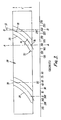
- FIGURE 3 shows a development of the peripheral surface of the latch operating member shown in Figure 2, showing the helical grooves on the surface of the latch operating member;
- FIGURE 4 is an isometic sketch, partially in section, of a locking mechanism in accordance with the invention for use with the latch operating apparatus of FIGURES 1 and 2:
- FIGURE 5 is an isometric view corresponding to FIGURE 4.
- FIGURE 6 is an isometic sketch of a locking member in the locked orientation
- Figure 7 is an isometric sketch of a locking member in the unlocked orientation
- Figure 8 is a view similar to Figure 4 showing a second embodiment
- Figure 9 is a view similar to Figure 4 showing a third embodiment.
- Figure 10 is a view similar to Figure 4 showing a fourth embodiment.
- FIGURE 1 shows two latch operating means which hereafter will generally be termed "handles" 10,10' for reasons which will become apparent. Since the working parts of handles 10 and 10' are mirror images only handle 10 will be described in detail though the significance of the mirror image relationship will be discussed.
- a conventional latch set according to British Standard BS 5872(1980) will be disposed between the handles 10 and 10' and the latch set provided with a spindle 44 of square section (see Figure 2)
- the handle 10 has a backing plate 12, and a handle housing formed by an outer casing 14 and a surface piece 16.
- the handles 10,10' are fixed to the door by bolts (not shown) passing through the door.
- the handles 10,10' in effect clamp the door between them.
- the bolts are obscured from view behind the outer casing 14.
- the backing plate also has an aperture (not shown) through which the latch spindle 44 passes.
- the surface piece 16 has two faces at right angles; a lateral face 18 which extends from the edge of the door along one side of the outer casing 14, and a face plate 20 which extends over the front of the outer casing 14 and has an aperture through which a push button 22 passes.
- the face plate 20 also has an extension beyond the casing 14 so that it may easily be grasped by a user.
- the push button 22 is connected to a yoke 23 formed of two axially extending arms 26 as will be seen more clearly in Figure 2.
- a yoke 23 formed of two axially extending arms 26 as will be seen more clearly in Figure 2.
- annular collar 25 of greater diameter than the hole in the face plate 20 which limits the linear movement of the button 22 and yoke 23 away from the base plate 12.
- a cylindrical slug 28 having two helical grooves 30, the grooves being spaced by 180° from one another about the slug 28.
- the arms 26 are likewise spaced from one another by 180°.
- Each ball bearing 32 is located in an appropriately configured cavity on the radially inner face of an arm 26 and on appropriately configured groove 30.
- the casing 14 is provided with an inner casing 15, the outer casing 14 and the inner casing 15 being preferably integral with one another.
- the inner casing 15 is formed with a pair of axially extending tracks 36 and a series of axially extending spaced ribs 31,34.
- the axially extending arms 26 of the yoke 23 fit in the tracks 36 so that the yoke 23 is free to slide axially with respect to the casing 14,15 but is prevented from rotating.
- the slug 28 is in the form of a hollow cylinder which may rotate about its axis within the inner casing 15.
- the slug 28 is open at the outer end (facing the button 22), but is partially closed at the inner end (facing the door) by a wall 29 which has a central opening 41 sufficiently large to accommodate the latch spindle 44.
- Means may be provided within the casing 14/15 to restrain the slug 28 from movement in an axial/longitudinal direction towards the door.
- a compression spring 40 acts between the button 22 and the wall 29 of the slug 28 to bias the slug 28 towards the backing plate 12 and the button 22 away from the back plate 12 towards face plate 20.
- a lost motion connector 50 is provided in the form of a collett having a cylindrical barrel 54 and a radial flange 56.
- the barrel 54 has a square-sectioned aperture 46 which receives the latch spindle 44 non-rotationally.
- the flange 56 has two equispaced radial tabs 58.
- the connector 50 is located in a recess 52 formed in the end wall 29 of the slug 28, the recess having a circular portion 60 dimensioned to receive the flange 56 and two radial part annular extensions 62 dimensioned to receive the tabs 58.
- the extensions 62 extend through a greater arc than the tabs 58 thereby allowing limited rotation of the connector 50 with respect to the slug 28.
- the slug 28 is therefore prevented from axial movement towards the door by the abutment of the barrel 54 against the backing plate 12, and is restrained from axial movement away from the door by the spring 40.
- the slug 28 is prevented from moving axially towards the door by the presence of the back plate 12 and so the interaction between the arms 26 and the grooves 30 through the ball bearings 32 results in rotation of the slug 28 as the yoke 23 moves axially.
- Rotation of the slug 28 causes the connector 50 to rotate by virtue of the tabs 58 engaging the respective extremities of the radial extensions 62 of the recess 52. This in turn rotates the latch spindle 44 and so withdraws the latch bolt.
- the direction of rotation is shown by the arrows in FIGURE 2.
- rotation of the latch spindle 44 will also cause rotation of the left hand connector 50.
- the left hand connector 50 instead of transferring this rotation to the left hand slug 28, the left hand connector 50 merely rotates taking up the lost motion allowed by the additional angular extent of the recess extensions 62 over and above the angular extent of the tabs 58.
- operation of the mechanism on one side of the door is entirely independent of the mechanism on the other side of the door (and vice versa) and so there is no tendency to rotate the other slug 28 nor to pull the other button 22 against its spring 40. Consequently, the operation can be smooth and easy to effect.
- FIGURE 3 is a development of the surface of the slug 28 showing one configuration which may be used for the two grooves 30.
- the grooves are from substantially semi-circular in section, the section being taken substantially at right angles to the pitch line 70 of each groove 30.
- the pitch line is in effect the centre line of the groove 30.
- the pitch line 70 is an arc of a circle.
- the helix angle is the angle between the tangent to the pitch line 70 at any point and a line on the surface of the slug 28 parallel to the slug axis. Such a line is shown as A-A.
- the pitch angle at the start of the thread 30 is designated ⁇ .
- the helix angle at the end of the thread 30 is designated ⁇ that being the angle between a tangent to the pitch line and the line shown at B-B.
- ⁇ is approximately 65°
- ⁇ is approximately 35°
- the mean helix angle is about 47°. It will therefore be seen that the helix angle of the grooves 30 across the slug 28 decreases from start to finish.
- the two grooves 30 shown in Figure 3 are substantially identical.
- the cusp shown at 72 is merely a consequence of the machine operation used to produce the groove 30. It otherwise has no consequence in the operation of the invention.
- British Standard BS 5872(1980) pertaining to latch sets requires a maximum rotational angle of the latch spindle of 50° to operate retraction of the latch bolt.
- points 76 and 78 show respectively the starting and finishing rest position of the centre of the ball bearings 32, both of which of course require to be within the length of the slug 28 shown at C in order to retain the ball bearing 32 captive between the groove 30 and the cavity in the associated arm 26.
- the angular rotation between points 76 and 78 is in excess of 50° at 55° to 60° thereby adequately providing the required 50° BS requirement.
- Figures 2C and 2D show a push button 22 and yoke 26 arrangement in which the ball bearing 32 is replaced by a pin 33 and roller bearing 34.
- the slug 28 in this embodiment will have grooves 30 with appropriate dimensions such that the bearings 34 roll along the side walls thereof, the arrangement otherwise functioning as described above.
- the push button 22 is provided with means by which it can be grasped by a user and pulled rather than pushed. In that form the rest position will be with the bearings 32 or 34 at the inner end of the slug 28, e.g. at 78, appropriate spring or other biassing means being provided.
- Figures 4 to 7 show a locking mechanism for the latch operating arrangement described above with reference to Figures 1 to 3.
- the latch operating arrangement can be locked and unlocked from one side only (the active side), shown on the left in Figures 4 and 5.
- Such an arrangement may be used for example on French Doors.
- the locking mechanism comprises an active locking member or spacer 111, a passive locking member or spacer 112 and a square section shaft 113.
- the shaft 113 extends through a bore in the latch spindle 44, in which it is free to rotate and move axially. It is rigidly connected to the active locking member 111 but passes slidably through a correspondingly square-sectioned hole in the passive locking member 112 thereby preventing relative rotation.
- the locking members 111, 112 are each part cylindrical and part rectangular in section, in that each has two parallel planar faces 114 and two curved faces 115 forming part of the same cylinder.
- Each slug 28 has a generally cylindrical bore 116 corresponding to the curved faces of a locking member 111, 112.
- the bore 116 additionally includes a pair of longitudinal ridges 117.
- the ridges 117 are arranged to prevent the locking member e.g.111 from entering the bore 116 in one orientation, as shown in Figure 6, while allowing the locking member to enter in another orientation, as shown in Figure 7.
- the ridges 117 are also shaped to allow the locking member a limited degree of rotation when within the bore - anti-clockwise in Figure 7.
- the locking button 122 is mounted for rotation with respect to the yoke 23 through an insert 118.
- the button 122 and insert 118 are therefore rotatable relative to the yoke 23 and are prevented from axial movement outwards from the yoke 23 by means of an annular flange 119 on the insert 118.
- the insert 118 has on its inner face a pip 123 and a central hole 124.
- the active locking member 111 has a corresponding identation 125 and central boss 126.
- the insert 118 and locking member 111 are urged into engagement by a spring 140 which corresponds to the spring 40 in the construction shown in Figures 1 and 2, acting between the locking member 111 and the interior of the slug 28.
- a spring 140 which corresponds to the spring 40 in the construction shown in Figures 1 and 2
- the locking members 111, 112 are positioned relative to their slugs 128 as shown in Figure 7.
- Axial movement of the locking button 122 will cause movement of the associated yoke 23 which in turn causes its slug 28 to rotate and so on to operate the latch set as previously described.
- This axial movement is permitted by the active locking member 111 entering the slug bore 116 with sufficient relative rotation between the slug 28 and locking member 111 for the slug 28 to rotate being allowed by the shape of the ridges 117.
- the shaft 113 moves with it and slides through the passive locking member 112 and into the cylinder 127, without rotating.
- the latch mechanism is operated in a similar manner, the passive locking member 112 entering its slug bore 116 by moving axially relative to the shaft 113 which is accommodated within the cylinder 127. Again, sufficient relative rotation between the locking member 112 and its slug 28 is allowed by the ridges 117 for that slug 28 to rotate to turn the latch spindle.
- the locking button 122 is turned through 90° relative to its yoke 23, the yoke 23 being prevented from rotation by the rails 36 in the casing 14,15.
- the slug 28 remains stationary with the yoke 23, but the active locking member 111 turns with the locking button 122, by virtue of the interacting pip 123, hole 124, indentation 125 and boss 126, until it attains an orientation relative to the slug 28 as shown in Figure 6.
- the ridges 117 obstruct axial movement of the locking member 111 such that it cannot enter the slug cavity 116 and thereby prevents the yoke 23 from moving axially.
- the slug 28 cannot be caused to rotate and the door latch cannot be released using the locking button 122
- the slug is thus restrained from rotation by the locking member 111 acting as spacer between the yoke 23 and the slug 28 and restraining linear movement.
- an annular slot 131 is provided in the insert 118 into which a pin 132 extends - see Figure 5.
- the pin 132 is fixed relative to the yoke 23 and the slot 131 is so dimensioned to limit the relative rotation as required.
- An indication or marker (not shown) is provided on the button 122 to show the rotational position of the locking button, i.e. locked or unlocked.
- FIG 8 is very similar to that shown in Figures 4 to 7 but is intended for use in applications where a door is required to be lockable and unlockable from one side, and unlockable in emergencies from the other side.
- An example of such an application is a bathroom door.
- This embodiment only differs in that the button 222 at the non-active side has a hole 223 and the spacer 227 has a slot 228 at the end adjacent the end of the button 222.
- a tool such as a screw driver can be inserted into the slot 228 through the hole 223 and turned, in order to turn the cylinder 227 and so the two locking members 111, 112, thereby unlocking the mechanism.
- FIG 9 is again similar to that shown in Figures 4 to 7 but in this case is intended for use on doors which can be locked in the way described above from one side and locked using a key from the other side. This arrangement may be used on privacy/office doors.
- This embodiment differs in that the previously described non-active side is active, being arranged to lock/unlock the mechanism by means of a standard key operated tumbler lock 321.
- This is located within the button 322 and replaces the cylinder 127, 227.
- the key acts either directly or indirectly on a second active locking member 312 to rotate the locking member 312 as described above and thereby to lock or unlock the mechanism.
- the locking member 312 has a cut-out 313 into which a spigot (not shown) on the lock cylinder operated by the key extends, the cut-out 313 being so shaped as to allow the key to return to its insertion/withdrawal position without moving the locking member 312 after moving the locking member 312 to the desired position.
- FIG. 10 is intended for use in those circumstances, such as with hotel doors, where the door is latch operated and lockable as described above from inside, the latch being operable from the other side using rotation by key rather than by a push button mechanism.
- the embodiment shown in Figure 10 is arranged so that when locked from the inside using the button-operated locking mechanism, the outside key operated lock is prevented from operating the latch, unless a special key is used.
- the right-hand latch operating means is replaced entirely by a standard five pin tumbler lock 421 to the mechanism of which block 422 is attached.
- the block 422 has a lost motion connector 423 which engages the latch spindle (not shown) so that rotation of the block 422 by operation of a key in the lock operates the latch set as described above.
- the lefthand or active side is modified from that described e.g. in relation to Figure 4 in that the shaft 413 passes slidably through correspondingly square-sectioned holes 431,432 in the active locking member 411 and the insert 418 respectively and is accommodated within a hollow cylinder 420 fixed to the button 122 and the insert 418 when the button 122 is pushed to operate the latch mechanism.
- the latch operating and locking functions are similar to those described above.
- the shaft 413 is connected to the block 422 through a fast helix 433.
- the shaft 413 is also turned. This in turn causes the fast helix 433 to draw itself and the shaft 413 into abutment with the end of the lock 421. Relative rotation between the fast helix 433 is ensured as the block 422 is prevented from rotation by its engagement with the latch spindle which is itself prevented from rotation by the slug 28 which cannot rotate since the yoke 23 cannot move axially.
- Standard keys for the five-pin tumbler lock 421 in this instance are of six-pin length.
- the key cannot be inserted to the extent necessary for it to be allowed to turn, and so the latch mechanism cannot be operated.
- a special key is provided of five pin length and so, when inserted into the lock 421, it is not obstructed by the fast helix 433.
- the special key can turn the block 422 and so operate the latch mechanism via the latch spindle.
- unlocked rotation of the latch spindle is accommodated in the left-hand side of the mechanism by virtue of the lost motion between the connector 50 and the slug 28.
- the locking member 411, insert 418, cylinder 420 and button 122 all rotate with the shaft 413 without obstruction.
Landscapes
- Engineering & Computer Science (AREA)
- Mechanical Engineering (AREA)
- Lock And Its Accessories (AREA)
Description
- This invention relates to operating means for a latch, for example a door latch, of the type stated in the precharacterising portion of claim 1.
- A door latch set as conventionally used comprises an insert fitted in the free edge of the door between its front and back faces having a bolt which in its extended position protrudes beyond the edge of the door into a recess in the door frame and in its retracted position is wholly within the door to allow the door to be opened. The bolt is conventionally moved between its retracted and extended positions by rotation of an element of the latch set by rotation of a square section spindle extending through the door. Rotation of the spindle is usually effected by action of a door handle or knob on the spindle. The bolt will usually be spring biased to its extended position.
- The bolt may be lockable in the extended or retracted position by a mechanism which prevents rotation of the handle or knob.
- The door handles or knobs conventionally used in these arrangements need to be rotated by the user. There are users for whom and circumstances in which rotation is difficult, inappropriate or undesirable. Therefore efforts have been made to produce arrangements in which a linear rather than rotatory action by the user is required to move the latch bolt between its retracted and extended positions. One such arrangement is provided in UK Patent No:862871 in which a press member extends through the door and out of the door on both sides, the press member having inclined cam surfaces which act upon a formation on or connected with the latch bolt, linear movement of the press member causing the latch bolt to retract by a camming action,the latch bolt being spring loaded to the extended position. This arrangements suffers the disadvantage of not using a conventional latch set, and in that movement of the press member on one side of the door causes movement of the other end on the other side of the door.
- A further suggestion utilising a linear movement towards or away from the door to retract or extend the latch bolt is described in Swedish Patent No:358700, in which rotation of a conventional square latch spindle is achieved either by rotation of a handle or by pressure on the handle towards the door. In the pressure operated mode a pin and helical groove arrangement translates linear movement of the member carrying the pin into rotary motion of the member carrying the groove, the rotary motion being transmitted through the spindle to the latch set in order to open the door.
- A still further suggestion operating on a very similar basis to that of Swedish Patent 358700 is disclosed in UK Patent No 2070128 which discloses those features set out in the precharacterising portion of claim 1 in which the door latch can be moved either by rotating or pushing a handle. When the handle is pushed, it in turn pushes a drum bearing a pin. The pin engages a helical groove in a slug which is caused to rotate. The slug has a square-section bore through which the latch spindle passes and so the latch bolt is caused to retract.
- The arrangements shown in UK 2070128 and Swedish Patent No:358700 suffer the disadvantage that these arrangements require a separate locking device if the door is to be locked.
- As with the arrangements shown in UK 2070128 and Swedish Patent No:358700, the present invention is concerned with operating means intended particularly (but not exclusively) to operate conventional latch sets such as those falling within British Standard BS 5872 (1980), the operating means using linear movement of an operatingmember towards or away from the door to cause rotational movement of a latch operating member by interaction of a thread on one member with a thread engaging cam on the other member.
- It is an object of the present invention to provide latch operating means, suitable for use with a conventional door latch set e.g. of the type falling within BS 5872(1980), having improved operating characteristics, greater ease and economy of production and enhanced performance particularly when used in pairs one on each side of a door. It is also an object to provide means to lock the latch operating means.
- The present invention is described primarily in terms of operation of latch sets for doors. The operating principles of the various improvements of the present invention may be applied, mutatis mutandis, to other forms of catch/handle/lock arrangements where translation of linear e.g. manual movement to rotational movement is required to bring about an operating effect. Thus the term "door" is not used restrictively and may extend to any similar moveable panel.
- According to the present invention there is provided a latch operating means having those features set out in the characterising portion of Claim 1. The spacer may preferably be located rotationally between the operating member and the latch operating member, a recess being provided in the operating member and/or the latch operating member, the spacer and recess being configured such that the spacer in a first rotational position may move linearly into the recess to allow linear movement of the operating member with respect to the latch operating member, but not in a second rotational position. That second rotational position will of course be angularly spaced from the first rotational position. The angular spacing is preferably in the region of 90°. Whatever the angular displacement required means are preferably provided such that the degree of rotational displacement can be easily and reproducibly effected by a user.
- The invention also extends to a latch operating set comprising first and second latch operating means, each as defined above and in which further means are provided to connect the spacers thereof such that movement of one spacer between its first and second rotational position likewise moves the other spacer.
- A further latch operating set of the present invention comprises a first latch operating means as described above together with further latch operating means, connection means being provided between the first and further latch operating means such that operation of the locking means of the first latch operating means restrains the further latch operating means from operation. When the first latch operating means is provided with a spacer as described above, the connection may be provided between the spacer of the first latch operating means and the further latch operating means, rotation of the spacer causing linear movement of the connection to or from the position where it restrains the further latch operating means from operation.
- The latch operating means of the invention may further be provided with a rotary lost motion connection between the latch operating member and the latch. In this form there will preferably be provided connector means to cooperate with a latch spindle for rotation thereof, the rotary lost motion connection being provided between the latch operating member and the said connector means. The connector may for example be provided with a recess to receive and rotate the spindle of a conventional latch set of the type falling within BS 5872 (1980). For that the spindle will normally be of square section and the recess in the connector means will be of corresponding section.
- The latch operating member may preferably be provided with a cylindrical recess having one or more part annular radial extension, the connector means being likewise cylindrical and having one or more radially extending lugs, rotation of the connector within the recess being limited by the circumferential extremities of the or each recess extension. At the extremities a side of the or each lug will abut the adjacent extremity of the or each recess extension. In an alternative the connector and operating arrangement may be vice versa that is to say the connector may be provided with a cylindrical recess having one or more part annular radial extension, the latch operating member having a coaxial cylindrical formation with one or more radially extending lugs such that rotation of the said formation within the recess is limited by the circumferential extremities of the or each recess extension.
- The extent of angular or rotatory lost motion permitted is preferably equivalent to the angular rotation of the latch operating member required to operate the latch.
- The invention also extends to the use of first and second latch operating means of this type, each connected by a latch spindle, operation of one latch operating means causing rotation of the spindle, that rotation being lost by the lost motion connection such that the latch operating member of the other is substantially unmoved.
- The latch operating means is preferably constructed such that the thread is a groove and the cam arrangement is provided by a bearing. For example the cam may be a pin having a roller bearing around its circumferential surface or the cam engagement of the members may be provided by a ball bearing, the ball being being captive between the groove on one member and a cavity on the other. The thread is preferably on the latch operating member but may be on the operating member.
- The thread of the operating means according to the invention preferably has a non-constant helix angle.
- It will be appreciated that in any of the various aspects and forms of the invention, while it may be preferred to bring about the retraction of the latch bolt by pressure on a push button towards the door, the reverse arrangement may usually be provided whereby retraction of the latch bolt is effected by pulling the operating member away from the door. Thus references to "push buttons" and the like throughout this specification may as appropriate be replaced, mutatis mutandis, by references to pulling.
- The latch operating member axis is parallel to and preferably substantially coincident with the linear movement path of the operating member.
- In further forms of the invention alternative combinations of thread and thread engaging cam may as appropriate be utilised. For example the thread may instead of a groove be a helical flange standing proud of one operating member mating in a manner to permit sliding with further means attached to the operating member, for example a twin pin or pin and bearing arrangement, the pins being spaced in a manner sufficient that the helical flange may run between them
- In any of the aspects or forms of the invention there may be a plurality of threads and thread engaged cams. In a preferred form there are two such threads and thread engaged cams at approximately 180° from each other about the cylindrical member axis. The invention may be carried into practice in various ways and some embodiments will now be described, by way of example, with reference to the accompanying drawings in which:-
- FIGURE 1 is a partially cutaway isometric sketch of a pair of door latch operating means of the general type with which the present invention is concerned in position but with the door omitted for clarity;
- FIGURE 2 is an isometric sketch of the operating members and latch operating members of the pair of operating means of FIGURE 1 but with the external housings removed;
- FIGURE 2A is an end view of a latch actuator;
- FIGURE 2B is an end view of the latch operating member;
- FIGURE 2C is a section of a further yoke and bearing arrangement;
- FIGURE 2D is an enlarged section of the bearing of FIGURE 2C;
- FIGURE 3 shows a development of the peripheral surface of the latch operating member shown in Figure 2, showing the helical grooves on the surface of the latch operating member;
- FIGURE 4 is an isometic sketch, partially in section, of a locking mechanism in accordance with the invention for use with the latch operating apparatus of FIGURES 1 and 2:
- FIGURE 5 is an isometric view corresponding to FIGURE 4;
- FIGURE 6 is an isometic sketch of a locking member in the locked orientation;
- Figure 7 is an isometric sketch of a locking member in the unlocked orientation;
- Figure 8 is a view similar to Figure 4 showing a second embodiment;
- Figure 9 is a view similar to Figure 4 showing a third embodiment; and
- Figure 10 is a view similar to Figure 4 showing a fourth embodiment.
- FIGURE 1 shows two latch operating means which hereafter will generally be termed "handles" 10,10' for reasons which will become apparent. Since the working parts of
handles 10 and 10' are mirror images only handle 10 will be described in detail though the significance of the mirror image relationship will be discussed. - A conventional latch set according to British Standard BS 5872(1980) will be disposed between the
handles 10 and 10' and the latch set provided with aspindle 44 of square section (see Figure 2) - Referring to FIGURES 1 and 2, the
handle 10 has abacking plate 12, and a handle housing formed by anouter casing 14 and asurface piece 16. Thehandles 10,10' are fixed to the door by bolts (not shown) passing through the door. Thehandles 10,10' in effect clamp the door between them. The bolts are obscured from view behind theouter casing 14. The backing plate also has an aperture (not shown) through which thelatch spindle 44 passes. Thesurface piece 16 has two faces at right angles; alateral face 18 which extends from the edge of the door along one side of theouter casing 14, and aface plate 20 which extends over the front of theouter casing 14 and has an aperture through which apush button 22 passes. Theface plate 20 also has an extension beyond thecasing 14 so that it may easily be grasped by a user. - The
push button 22 is connected to ayoke 23 formed of two axially extendingarms 26 as will be seen more clearly in Figure 2. There is anannular collar 25 of greater diameter than the hole in theface plate 20 which limits the linear movement of thebutton 22 andyoke 23 away from thebase plate 12. - Between the
arms 26 is located acylindrical slug 28 having twohelical grooves 30, the grooves being spaced by 180° from one another about theslug 28. Thearms 26 are likewise spaced from one another by 180°. - Between each
arm 26 and itsadjacent groove 30 is held captive aball bearing 32. Eachball bearing 32 is located in an appropriately configured cavity on the radially inner face of anarm 26 and on appropriately configuredgroove 30. - The
casing 14 is provided with aninner casing 15, theouter casing 14 and theinner casing 15 being preferably integral with one another. - The
inner casing 15 is formed with a pair of axially extendingtracks 36 and a series of axially extending spacedribs axially extending arms 26 of theyoke 23 fit in thetracks 36 so that theyoke 23 is free to slide axially with respect to thecasing - The
slug 28 is in the form of a hollow cylinder which may rotate about its axis within theinner casing 15. Theslug 28 is open at the outer end (facing the button 22), but is partially closed at the inner end (facing the door) by awall 29 which has acentral opening 41 sufficiently large to accommodate thelatch spindle 44. - Means (not shown) may be provided within the
casing 14/15 to restrain theslug 28 from movement in an axial/longitudinal direction towards the door. - A
compression spring 40 acts between thebutton 22 and thewall 29 of theslug 28 to bias theslug 28 towards the backingplate 12 and thebutton 22 away from theback plate 12 towardsface plate 20. - A lost
motion connector 50 is provided in the form of a collett having acylindrical barrel 54 and aradial flange 56. Thebarrel 54 has a square-sectionedaperture 46 which receives thelatch spindle 44 non-rotationally. As shown in FIGURES 2A and 2B, theflange 56 has two equispacedradial tabs 58. Theconnector 50 is located in arecess 52 formed in theend wall 29 of theslug 28, the recess having acircular portion 60 dimensioned to receive theflange 56 and two radial partannular extensions 62 dimensioned to receive thetabs 58. Theextensions 62 extend through a greater arc than thetabs 58 thereby allowing limited rotation of theconnector 50 with respect to theslug 28. Theslug 28 is therefore prevented from axial movement towards the door by the abutment of thebarrel 54 against thebacking plate 12, and is restrained from axial movement away from the door by thespring 40. - Operation of the device to turn the
latch spindle 44 and so withdraw the latch bolt to enable the door to be opened is achieved simply by pressing thebutton 22. The mechanism works as follows: - Pressure on the
button 22 moves theyoke 23 towards the door and at the same time compresses thespring 40. There is sufficient axial clearance between theyoke 23 and theslug 28 to allow theyoke 23 to move in this way. The movement would tend to make thearms 26 rotate to follow thegrooves 30 due to the interaction between theyoke 23 and theslug 28 brought about by theball bearings 32; however, thearms 26 of theyoke 23 are constrained to move only axially by thetracks 36. Furthermore, theslug 28 is prevented from moving axially towards the door by the presence of theback plate 12 and so the interaction between thearms 26 and thegrooves 30 through theball bearings 32 results in rotation of theslug 28 as theyoke 23 moves axially. - Rotation of the
slug 28 causes theconnector 50 to rotate by virtue of thetabs 58 engaging the respective extremities of theradial extensions 62 of therecess 52. This in turn rotates thelatch spindle 44 and so withdraws the latch bolt. The direction of rotation is shown by the arrows in FIGURE 2. When the pressure on thebutton 22 is released, thespring 40 and the latch bolt spring (not shown), if any, return the latch set to the bolt-extended position. - The significance of the lost motion coupling between the
connector 50 and theslug 28 can be most clearly understood upon consideration of the left hand part (handle 10') of FIGURE 2. Bearing in mind the fact that the twoslugs 28 are mirror images, it wll be appreciated that theconnector 50 andslug 28 in the right-hand portion will be in the same relative rotational positions as those in the left-hand portion. Thus, rotation movement of the right-hand slug 28 in the direction of the arrows will result in immediate rotation of the right-hand connector 50 and in turn of thelatch spindle 44. - Now, rotation of the
latch spindle 44 will also cause rotation of theleft hand connector 50. However, instead of transferring this rotation to theleft hand slug 28, theleft hand connector 50 merely rotates taking up the lost motion allowed by the additional angular extent of therecess extensions 62 over and above the angular extent of thetabs 58. As a result, operation of the mechanism on one side of the door is entirely independent of the mechanism on the other side of the door (and vice versa) and so there is no tendency to rotate theother slug 28 nor to pull theother button 22 against itsspring 40. Consequently, the operation can be smooth and easy to effect. - The mirror image relationship of the
slug 28 also means that operation of the mechanism on either side of the door will cause rotation oflatch spindle 44 in the same sense. This can also be seen most clearly in FIGURE 2. - Care of course needs to be exercised on assembly of the
handles 10,10' to ensure that lost motion in the correct sense is provided between the cooperating mechanisms. - FIGURE 3 is a development of the surface of the
slug 28 showing one configuration which may be used for the twogrooves 30. The grooves are from substantially semi-circular in section, the section being taken substantially at right angles to thepitch line 70 of eachgroove 30. The pitch line is in effect the centre line of thegroove 30. - In the arrangement shown in Figure 3, the
pitch line 70 is an arc of a circle. The helix angle is the angle between the tangent to thepitch line 70 at any point and a line on the surface of theslug 28 parallel to the slug axis. Such a line is shown as A-A. The pitch angle at the start of thethread 30 is designated α. The helix angle at the end of thethread 30 is designated β that being the angle between a tangent to the pitch line and the line shown at B-B. In this particular embodiment of the invention α is approximately 65°, β is approximately 35° and the mean helix angle is about 47°. It will therefore be seen that the helix angle of thegrooves 30 across theslug 28 decreases from start to finish. - The two
grooves 30 shown in Figure 3 are substantially identical. The cusp shown at 72 is merely a consequence of the machine operation used to produce thegroove 30. It otherwise has no consequence in the operation of the invention. - British Standard BS 5872(1980) pertaining to latch sets requires a maximum rotational angle of the latch spindle of 50° to operate retraction of the latch bolt. On the drawing, points 76 and 78 show respectively the starting and finishing rest position of the centre of the
ball bearings 32, both of which of course require to be within the length of theslug 28 shown at C in order to retain theball bearing 32 captive between thegroove 30 and the cavity in the associatedarm 26. The angular rotation betweenpoints - It will be appreciated that the corresponding projections for the slug 30' are mirror images of those shown in Figure 3.
- Figures 2C and 2D show a
push button 22 andyoke 26 arrangement in which theball bearing 32 is replaced by apin 33 androller bearing 34. Theslug 28 in this embodiment will havegrooves 30 with appropriate dimensions such that thebearings 34 roll along the side walls thereof, the arrangement otherwise functioning as described above. - In a further embodiment of the invention (not shown) the
push button 22 is provided with means by which it can be grasped by a user and pulled rather than pushed. In that form the rest position will be with thebearings slug 28, e.g. at 78, appropriate spring or other biassing means being provided. - Figures 4 to 7 show a locking mechanism for the latch operating arrangement described above with reference to Figures 1 to 3. In this embodiment, the latch operating arrangement can be locked and unlocked from one side only (the active side), shown on the left in Figures 4 and 5. Such an arrangement may be used for example on French Doors.
- The locking mechanism comprises an active locking member or
spacer 111, a passive locking member orspacer 112 and asquare section shaft 113. Theshaft 113 extends through a bore in thelatch spindle 44, in which it is free to rotate and move axially. It is rigidly connected to theactive locking member 111 but passes slidably through a correspondingly square-sectioned hole in thepassive locking member 112 thereby preventing relative rotation. - The locking
members curved faces 115 forming part of the same cylinder. Eachslug 28 has a generallycylindrical bore 116 corresponding to the curved faces of a lockingmember bore 116 additionally includes a pair oflongitudinal ridges 117. Theridges 117 are arranged to prevent the locking member e.g.111 from entering thebore 116 in one orientation, as shown in Figure 6, while allowing the locking member to enter in another orientation, as shown in Figure 7. Theridges 117 are also shaped to allow the locking member a limited degree of rotation when within the bore - anti-clockwise in Figure 7. - On the active side, the
locking button 122 is mounted for rotation with respect to theyoke 23 through aninsert 118. Thebutton 122 and insert 118 are therefore rotatable relative to theyoke 23 and are prevented from axial movement outwards from theyoke 23 by means of an annular flange 119 on theinsert 118. - The
insert 118 has on its inner face apip 123 and acentral hole 124. Theactive locking member 111 has acorresponding identation 125 andcentral boss 126. Theinsert 118 and lockingmember 111 are urged into engagement by aspring 140 which corresponds to thespring 40 in the construction shown in Figures 1 and 2, acting between the lockingmember 111 and the interior of theslug 28. Thus, relative rotation between theinsert 118 and the lockingmeber 111 is prevented and rotation of thebutton 122 will cause rotation of the lockingmember 111. - On the non-active side, there is a
hollow cylinder 127 between thepassive locking member 112 and thebutton 22, themember 112 being urged towards thebutton 22 by asecond spring 140 in the same way as theactive locking member 111. - The relationship between the
yokes 23, slugs 28 and latch mechanism in this construction is other wise identical to that described with reference to Figures 1 and 2 above. The system as a whole operates as follows: - In the unlocked mode, the locking
members locking button 122 will cause movement of the associatedyoke 23 which in turn causes itsslug 28 to rotate and so on to operate the latch set as previously described. This axial movement is permitted by theactive locking member 111 entering the slug bore 116 with sufficient relative rotation between theslug 28 and lockingmember 111 for theslug 28 to rotate being allowed by the shape of theridges 117. As the lockingmember 111 moves axially, theshaft 113 moves with it and slides through thepassive locking member 112 and into thecylinder 127, without rotating. - If the
button 22 is pushed, the latch mechanism is operated in a similar manner, thepassive locking member 112 entering its slug bore 116 by moving axially relative to theshaft 113 which is accommodated within thecylinder 127. Again, sufficient relative rotation between the lockingmember 112 and itsslug 28 is allowed by theridges 117 for thatslug 28 to rotate to turn the latch spindle. - In order to lock the mechanism, the
locking button 122 is turned through 90° relative to itsyoke 23, theyoke 23 being prevented from rotation by therails 36 in thecasing slug 28 remains stationary with theyoke 23, but theactive locking member 111 turns with thelocking button 122, by virtue of the interactingpip 123,hole 124,indentation 125 andboss 126, until it attains an orientation relative to theslug 28 as shown in Figure 6. In this position theridges 117 obstruct axial movement of the lockingmember 111 such that it cannot enter theslug cavity 116 and thereby prevents theyoke 23 from moving axially. Thus, theslug 28 cannot be caused to rotate and the door latch cannot be released using thelocking button 122 The slug is thus restrained from rotation by the lockingmember 111 acting as spacer between theyoke 23 and theslug 28 and restraining linear movement. - At the same time, rotation of the
active locking member 111 rotates theshaft 113 which in turn rotates thepassive locking member 112 into the position shown in Figure 6. Thus, axial movement of the yoke on the non-active side is also obstructed by the same means, so preventing operation of the latch mechanism using thebutton 22. - In order to limit rotation of the
locking button 122 to the angle required by the positioning of theridges 117, in thiscase 90°, anannular slot 131 is provided in theinsert 118 into which apin 132 extends - see Figure 5. Thepin 132 is fixed relative to theyoke 23 and theslot 131 is so dimensioned to limit the relative rotation as required. An indication or marker (not shown) is provided on thebutton 122 to show the rotational position of the locking button, i.e. locked or unlocked. - The embodiment shown in Figure 8 is very similar to that shown in Figures 4 to 7 but is intended for use in applications where a door is required to be lockable and unlockable from one side, and unlockable in emergencies from the other side. An example of such an application is a bathroom door.
- This embodiment only differs in that the
button 222 at the non-active side has ahole 223 and thespacer 227 has aslot 228 at the end adjacent the end of thebutton 222. Thus, in an emergency, a tool such as a screw driver can be inserted into theslot 228 through thehole 223 and turned, in order to turn thecylinder 227 and so the two lockingmembers - The embodiment shown in Figure 9 is again similar to that shown in Figures 4 to 7 but in this case is intended for use on doors which can be locked in the way described above from one side and locked using a key from the other side. This arrangement may be used on privacy/office doors.
- This embodiment differs in that the previously described non-active side is active, being arranged to lock/unlock the mechanism by means of a standard key operated
tumbler lock 321. This is located within thebutton 322 and replaces thecylinder member 312 to rotate the lockingmember 312 as described above and thereby to lock or unlock the mechanism. The lockingmember 312 has a cut-out 313 into which a spigot (not shown) on the lock cylinder operated by the key extends, the cut-out 313 being so shaped as to allow the key to return to its insertion/withdrawal position without moving the lockingmember 312 after moving the lockingmember 312 to the desired position. - The embodiment shown in Figure 10 is intended for use in those circumstances, such as with hotel doors, where the door is latch operated and lockable as described above from inside, the latch being operable from the other side using rotation by key rather than by a push button mechanism. In addition, it is arranged so that when locked from the inside using the button-operated locking mechanism, the outside key operated lock is prevented from operating the latch, unless a special key is used.
- In the embodiment of Figure 10, the right-hand latch operating means is replaced entirely by a standard five
pin tumbler lock 421 to the mechanism of which block 422 is attached. Theblock 422 has a lostmotion connector 423 which engages the latch spindle (not shown) so that rotation of theblock 422 by operation of a key in the lock operates the latch set as described above. - The lefthand or active side is modified from that described e.g. in relation to Figure 4 in that the
shaft 413 passes slidably through correspondingly square-sectioned holes 431,432 in theactive locking member 411 and theinsert 418 respectively and is accommodated within ahollow cylinder 420 fixed to thebutton 122 and theinsert 418 when thebutton 122 is pushed to operate the latch mechanism. However, the latch operating and locking functions are similar to those described above. - The
shaft 413 is connected to theblock 422 through afast helix 433. Thus, when thelocking button 122 is turned to lock the locking mechanism, theshaft 413 is also turned. This in turn causes thefast helix 433 to draw itself and theshaft 413 into abutment with the end of thelock 421. Relative rotation between thefast helix 433 is ensured as theblock 422 is prevented from rotation by its engagement with the latch spindle which is itself prevented from rotation by theslug 28 which cannot rotate since theyoke 23 cannot move axially. - Standard keys for the five-
pin tumbler lock 421 in this instance are of six-pin length. Thus, When thefast helix 433 abuts the end of thelock 421, the key cannot be inserted to the extent necessary for it to be allowed to turn, and so the latch mechanism cannot be operated. However, in this instance, a special key is provided of five pin length and so, when inserted into thelock 421, it is not obstructed by thefast helix 433. Thus the special key can turn theblock 422 and so operate the latch mechanism via the latch spindle. When unlocked rotation of the latch spindle is accommodated in the left-hand side of the mechanism by virtue of the lost motion between theconnector 50 and theslug 28. The lockingmember 411, insert 418,cylinder 420 andbutton 122 all rotate with theshaft 413 without obstruction. - It will be appreciated that while various embodiments have been described individually, the differing variants or features thereof may be combined in any convenient manner to achieve any particular desired characteristics.
Claims (10)
- Latch operating means in which linear movement of an operating member (122, 23) including a push-button (122) causes rotational movement of a latch operating member (28) by interaction of a thread (30) on one member with a thread engaging cam (32) on the other member, characterised by locking means, the locking means comprising a spacer (111) movable between a first position allowing linear movement of the operating member (122, 23) with respect to the latch operating member (28) and a second position in which the spacer (111) is located between the push-button (122) of the operating member (122, 23) and the latch operating member (28) so as to maintain linear separation thereof and thereby restrain linear movement of the operating member (122, 23) with respect to the latch operating member (28).
- Latch operating means as claimed in Claim 1 in which the spacer (111) is located rotationally between the push-button (122) and the latch operating member (28), a recess being provided in the operating and/or the latch operating member, the spacer (111) and recess being configured such that the spacer in a first rotational position may move linearly into the recess to allow linear movement of the operating member (122, 23) with respect to the latch operating member (28) but not in a second rotational position.
- Latch operating means as claimed in Claim 2 in which the first rotational position and the second rotational position are angularly spaced by substantially 90°.
- Latch operating means as claimed in Claim 2 or Claim 3 in which rotation of the spacer (111) is effected by rotation of the push button (122).
- A latch operating set comprising first latch operating means as claimed in any of Claims 1 to 4 and further latch operating means, connecting means (44, 113, 413) being provided to connect the first and further latch operating means such that operation of the locking means of the first latch operating means restrains the further latch operating means from operation.
- A latch operating set as claimed in Claim 5 in which movement of the spacer (111) from the first position to the second position causes linear movement of the connecting means (113) to a position in which it restrains the further latch operating means from operation.
- A latch operating set as claimed in Claim 5 in which movement of the spacer (111) from the first position to the second position causes rotational movement of the connecting means (413) to a position in which it restrains the further latch operating means from operation.
- A latch operating set as claimed in any one of Claims 5 to 7 in which the further latch operating means includes a tumbler lock (321, 421), locking of the tumbler lock restraining both the first and further latch operating means from operation.
- A latch operating set as claimed in Claim 8 in which both the first and further latch operating means are releasable from the respective positions in which they are restrained from operation by unlocking of the tumbler lock (321, 421).
- A latch operating set comprising first and second latch operating means each as claimed in any one of Claims 1 to 3 including means (44) for connection of the spacers (111, 112) thereof such that movement of one spacer (111) between its first and second position likewise moves the other spacer (112).
Priority Applications (1)
| Application Number | Priority Date | Filing Date | Title |
|---|---|---|---|
| AT86300729T ATE61843T1 (en) | 1985-02-05 | 1986-02-04 | LOCK OPERATING MECHANISM. |
Applications Claiming Priority (4)
| Application Number | Priority Date | Filing Date | Title |
|---|---|---|---|
| GB858502922A GB8502922D0 (en) | 1985-02-05 | 1985-02-05 | Door latch operating means |
| GB8502922 | 1985-02-05 | ||
| GB858515401A GB8515401D0 (en) | 1985-06-18 | 1985-06-18 | Door latch operating means |
| GB8515401 | 1985-06-18 |
Related Child Applications (2)
| Application Number | Title | Priority Date | Filing Date |
|---|---|---|---|
| EP19900200651 Division EP0381301A3 (en) | 1985-02-05 | 1986-02-04 | Latch operating means |
| EP90200651.9 Division-Into | 1990-03-12 |
Publications (3)
| Publication Number | Publication Date |
|---|---|
| EP0190916A2 EP0190916A2 (en) | 1986-08-13 |
| EP0190916A3 EP0190916A3 (en) | 1988-09-14 |
| EP0190916B1 true EP0190916B1 (en) | 1991-03-20 |
Family
ID=26288770
Family Applications (4)
| Application Number | Title | Priority Date | Filing Date |
|---|---|---|---|
| EP19860300730 Withdrawn EP0190917A3 (en) | 1985-02-05 | 1986-02-04 | Latch operating means |
| EP19860300732 Expired - Lifetime EP0193291B1 (en) | 1985-02-05 | 1986-02-04 | Latch operating set |
| EP19860300729 Expired - Lifetime EP0190916B1 (en) | 1985-02-05 | 1986-02-04 | Latch operating means |
| EP19900200651 Ceased EP0381301A3 (en) | 1985-02-05 | 1986-02-04 | Latch operating means |
Family Applications Before (2)
| Application Number | Title | Priority Date | Filing Date |
|---|---|---|---|
| EP19860300730 Withdrawn EP0190917A3 (en) | 1985-02-05 | 1986-02-04 | Latch operating means |
| EP19860300732 Expired - Lifetime EP0193291B1 (en) | 1985-02-05 | 1986-02-04 | Latch operating set |
Family Applications After (1)
| Application Number | Title | Priority Date | Filing Date |
|---|---|---|---|
| EP19900200651 Ceased EP0381301A3 (en) | 1985-02-05 | 1986-02-04 | Latch operating means |
Country Status (4)
| Country | Link |
|---|---|
| US (1) | US4813723A (en) |
| EP (4) | EP0190917A3 (en) |
| DE (2) | DE3678856D1 (en) |
| GB (3) | GB2170551B (en) |
Families Citing this family (26)
| Publication number | Priority date | Publication date | Assignee | Title |
|---|---|---|---|---|
| GB2211883B (en) * | 1987-11-05 | 1992-06-17 | Titon Hardware | Latch mechanism. |
| ES2008987A6 (en) * | 1988-05-05 | 1989-08-16 | Ojmar Sa | Lock with a retractable knob |
| US5029916A (en) * | 1990-10-24 | 1991-07-09 | Chiu I Hsin | Push-pull door lock |
| ES2058000B1 (en) * | 1991-12-18 | 1996-09-01 | Recio Alberto Rey | MECHANICAL LOCKING SYSTEM FOR LOCK BULBS AND THE LIKE. |
| US5551188A (en) * | 1995-02-06 | 1996-09-03 | Davlantes; George N. | Security knob on pet door panel |
| US5657653A (en) * | 1995-08-10 | 1997-08-19 | Schlage Lock Company | Dual lock with simultaneous retraction of latch and deadbolt by inside lever and uncoulpler between driving spindle and the lever |
| WO2005010301A2 (en) * | 2003-07-17 | 2005-02-03 | Herbert Viehhauser | Actuating handle for a door lock |
| US8393654B2 (en) * | 2003-08-26 | 2013-03-12 | Kwikset Corporation | Turn-button with leading helical end portion |
| ITMC20060150A1 (en) * | 2006-11-13 | 2008-05-14 | So Ge Mi Spa | OPENING AND CLOSING DEVICE FOR DOORS. |
| DE102007027845A1 (en) * | 2007-06-13 | 2008-12-18 | Huf Hülsbeck & Fürst Gmbh & Co. Kg | Device for actuating a closure of a movable part |
| FR2952108B1 (en) * | 2009-11-02 | 2011-12-16 | Adler Sas | DEVICE FOR LOCKING THE DOORS OF A DISPLAY |
| FR2955882B1 (en) * | 2010-02-01 | 2012-01-27 | Patrick Yves Galtier | DEVICE FOR OPENING OR CLOSING A DOOR BY SIMPLE TRACTION OR PRESSURE ON A PUSH BUTTON |
| US8844389B2 (en) * | 2011-12-14 | 2014-09-30 | Woodward Hrt, Inc. | Automatically locking linear actuator |
| GB2498340A (en) * | 2012-01-09 | 2013-07-17 | Albertus Abraham Petrus De Groot | A latch operating device comprising a push button and helical cam |
| US10662671B2 (en) | 2013-12-05 | 2020-05-26 | Ptmw, Inc. | Lock assembly with locking handle |
| US10533347B2 (en) * | 2014-11-25 | 2020-01-14 | Ryan Eley | Emergency access privacy lock and access key |
| IT201600081787A1 (en) * | 2016-08-03 | 2018-02-03 | Alban Giacomo Spa | LOCK FOR DOORS AND / OR WINDOWS |
| DE102017100935B4 (en) | 2017-01-18 | 2024-08-01 | Lisa Dräxlmaier GmbH | Locking mechanism for a lid of a storage compartment of a motor vehicle |
| TWM582083U (en) * | 2019-05-24 | 2019-08-11 | 伍鐌科技股份有限公司 | Structure for reducing height of fastener |
| WO2022032700A1 (en) * | 2020-08-13 | 2022-02-17 | Nanjing Easthouse Electrical Co., Ltd. | Passive electronic locks and methods of using the same |
| CA3158427C (en) | 2021-05-05 | 2026-03-31 | Assa Abloy Access And Egress Hardware Group, Inc. | Door lock assembly |
| CA3158419A1 (en) | 2021-05-05 | 2022-11-05 | Assa Abloy Access And Egress Hardware Group, Inc. | Door lock assembly with waggle reduction |
| US12559968B2 (en) * | 2021-05-05 | 2026-02-24 | Assa Abloy Access And Egress Hardware Group, Inc. | Door lock assembly with self adjusting spindles |
| US12421759B2 (en) | 2021-05-05 | 2025-09-23 | Assa Abloy Access And Egress Hardware Group, Inc. | Door lock assembly with safeguarding against bypassing |
| US20250257589A1 (en) * | 2024-02-08 | 2025-08-14 | Sargent Manufacturing Company | Exit device privacy function |
| CN222615037U (en) * | 2024-06-06 | 2025-03-14 | 中山市黑迪箭牌锁业有限公司 | Bathroom lock structure |
Family Cites Families (19)
| Publication number | Priority date | Publication date | Assignee | Title |
|---|---|---|---|---|
| DE173463C (en) * | ||||
| BE435387A (en) * | ||||
| DE407706C (en) * | 1923-12-20 | 1924-12-30 | Valdemar Lange Nielsen | Door lock |
| FR773366A (en) * | 1934-03-15 | 1934-11-16 | Lock | |
| DE693087C (en) * | 1937-01-29 | 1940-07-02 | Emil Ady | Lock with damping device to eliminate annoying lock noises |
| US2484738A (en) * | 1947-10-20 | 1949-10-11 | Hay B Reid | Latching device |
| US2699353A (en) * | 1952-12-05 | 1955-01-11 | Charles E Nagy | Pistol grip doorknob |
| FR1129222A (en) * | 1955-07-25 | 1957-01-17 | Vachette Ets | Lock enhancements |
| GB862871A (en) | 1956-10-08 | 1961-03-15 | Desmond Edward Charles Webster | Improvements in or relating to fastening devices for doors |
| US3183418A (en) * | 1961-08-14 | 1965-05-11 | George S Cherniak | Rotary solenoid |
| FR1351945A (en) * | 1963-03-26 | 1964-02-07 | Michallon Prat Ets | Central bolt control with amplified opening stroke for door lock buttons or similar |
| US3191780A (en) * | 1963-08-30 | 1965-06-29 | Baker Equipment Eng Co | Boom rotating mechanism |
| US3264025A (en) * | 1964-04-14 | 1966-08-02 | Edward M Hawes | Push-pull door latch construction |
| GB1161167A (en) * | 1967-04-22 | 1969-08-13 | Strebor Diecasting Company Ltd | Improvements in Door Locks. |
| SE358700B (en) | 1971-03-12 | 1973-08-06 | P Braendstroem | |
| US4193377A (en) * | 1978-06-02 | 1980-03-18 | Weldy Levon R | Panel structure for animal pens |
| GB2070128B (en) * | 1979-04-18 | 1982-12-08 | Cartwright G Ltd | Operating mechanism for door latch apparatus |
| JPS5833348B2 (en) * | 1979-08-23 | 1983-07-19 | 基博 五反田 | locking device |
| FR2547851B1 (en) * | 1983-06-22 | 1985-09-13 | Arouete J | REMOTE CONTROLLED ELECTRIC LOCK |
-
1986
- 1986-02-04 EP EP19860300730 patent/EP0190917A3/en not_active Withdrawn
- 1986-02-04 DE DE8686300732T patent/DE3678856D1/en not_active Expired - Fee Related
- 1986-02-04 DE DE8686300729T patent/DE3678177D1/en not_active Expired - Fee Related
- 1986-02-04 EP EP19860300732 patent/EP0193291B1/en not_active Expired - Lifetime
- 1986-02-04 EP EP19860300729 patent/EP0190916B1/en not_active Expired - Lifetime
- 1986-02-04 GB GB8602701A patent/GB2170551B/en not_active Expired
- 1986-02-04 EP EP19900200651 patent/EP0381301A3/en not_active Ceased
- 1986-02-04 GB GB8602700A patent/GB2170550B/en not_active Expired
- 1986-02-04 GB GB8602702A patent/GB2170552B/en not_active Expired
- 1986-02-05 US US06/826,461 patent/US4813723A/en not_active Expired - Lifetime
Also Published As
| Publication number | Publication date |
|---|---|
| GB8602702D0 (en) | 1986-03-12 |
| EP0193291A3 (en) | 1988-09-28 |
| EP0190916A3 (en) | 1988-09-14 |
| GB8602701D0 (en) | 1986-03-12 |
| EP0190917A2 (en) | 1986-08-13 |
| GB2170550A (en) | 1986-08-06 |
| EP0190916A2 (en) | 1986-08-13 |
| GB2170551B (en) | 1988-08-17 |
| DE3678856D1 (en) | 1991-05-29 |
| DE3678177D1 (en) | 1991-04-25 |
| GB2170551A (en) | 1986-08-06 |
| EP0193291A2 (en) | 1986-09-03 |
| EP0381301A3 (en) | 1990-11-07 |
| EP0193291B1 (en) | 1991-04-24 |
| GB2170552A (en) | 1986-08-06 |
| GB2170550B (en) | 1988-08-17 |
| EP0381301A2 (en) | 1990-08-08 |
| GB2170552B (en) | 1988-08-17 |
| GB8602700D0 (en) | 1986-03-12 |
| US4813723A (en) | 1989-03-21 |
| EP0190917A3 (en) | 1988-09-14 |
Similar Documents
| Publication | Publication Date | Title |
|---|---|---|
| EP0193291B1 (en) | Latch operating set | |
| US5634359A (en) | Removable core lock with latch alignment and limited latch rotation | |
| US5816086A (en) | Axial moving pushbutton for a lock having rotary locking and release motions | |
| KR100541181B1 (en) | High strength lever handle lock mechanism | |
| US12416185B2 (en) | Multifunction hub core for mortise lock and method of assembly | |
| US20230022564A1 (en) | Combination lock | |
| JP2000507321A (en) | Lock with removable plug | |
| JPS6050949B2 (en) | combination tablet | |
| GB2492829A (en) | Double lock cylinder with key cylinder, thumbturn, and mis-alignment clutch | |
| EP0237319B1 (en) | Lock set | |
| EP0195293A2 (en) | A disc type cylinder lock | |
| US4028917A (en) | Key retaining cylinder for a lock | |
| US5551263A (en) | Lock with dead bolt camming action on 90 degree lock cylinder rotation | |
| US6679090B1 (en) | Removable core lock with increased rotation | |
| WO2009109961A2 (en) | High-security rotating bolt lock | |
| JP7812007B2 (en) | Locks and locking devices | |
| CN217897540U (en) | Lock and device thereof | |
| CN101990590A (en) | T-handle actuator and latch | |
| JPS62125178A (en) | Latch operation apparatus | |
| EP0162158A1 (en) | Cylinder lock and key | |
| JPS5821866Y2 (en) | Sliding door lock cylinder device | |
| CN222667906U (en) | Dual key unlocking device | |
| EP4365390B1 (en) | Cabinet lock | |
| KR200204006Y1 (en) | A lock for furniture | |
| KR200191537Y1 (en) | Free prevention means of lock |
Legal Events
| Date | Code | Title | Description |
|---|---|---|---|
| PUAI | Public reference made under article 153(3) epc to a published international application that has entered the european phase |
Free format text: ORIGINAL CODE: 0009012 |
|
| AK | Designated contracting states |
Kind code of ref document: A2 Designated state(s): AT BE CH DE FR GB IT LI LU NL SE |
|
| PUAL | Search report despatched |
Free format text: ORIGINAL CODE: 0009013 |
|
| RHK1 | Main classification (correction) |
Ipc: E05C 1/14 |
|
| AK | Designated contracting states |
Kind code of ref document: A3 Designated state(s): AT BE CH DE FR GB IT LI LU NL SE |
|
| 17P | Request for examination filed |
Effective date: 19890306 |
|
| 17Q | First examination report despatched |
Effective date: 19890621 |
|
| ITF | It: translation for a ep patent filed | ||
| GRAA | (expected) grant |
Free format text: ORIGINAL CODE: 0009210 |
|
| AK | Designated contracting states |
Kind code of ref document: B1 Designated state(s): AT BE CH DE FR GB IT LI LU NL SE |
|
| PG25 | Lapsed in a contracting state [announced via postgrant information from national office to epo] |
Ref country code: SE Effective date: 19910320 Ref country code: NL Effective date: 19910320 Ref country code: LI Effective date: 19910320 Ref country code: CH Effective date: 19910320 Ref country code: BE Effective date: 19910320 Ref country code: AT Effective date: 19910320 |
|
| REF | Corresponds to: |
Ref document number: 61843 Country of ref document: AT Date of ref document: 19910415 Kind code of ref document: T |
|
| XX | Miscellaneous (additional remarks) |
Free format text: TEILANMELDUNG 90200651.9 EINGEREICHT AM 04/02/86. |
|
| REF | Corresponds to: |
Ref document number: 3678177 Country of ref document: DE Date of ref document: 19910425 |
|
| REG | Reference to a national code |
Ref country code: CH Ref legal event code: PL |
|
| EN | Fr: translation not filed | ||
| PG25 | Lapsed in a contracting state [announced via postgrant information from national office to epo] |
Ref country code: FR Effective date: 19910809 |
|
| NLV1 | Nl: lapsed or annulled due to failure to fulfill the requirements of art. 29p and 29m of the patents act | ||
| PLBE | No opposition filed within time limit |
Free format text: ORIGINAL CODE: 0009261 |
|
| STAA | Information on the status of an ep patent application or granted ep patent |
Free format text: STATUS: NO OPPOSITION FILED WITHIN TIME LIMIT |
|
| PG25 | Lapsed in a contracting state [announced via postgrant information from national office to epo] |
Ref country code: LU Free format text: LAPSE BECAUSE OF NON-PAYMENT OF DUE FEES Effective date: 19920229 |
|
| 26N | No opposition filed | ||
| REG | Reference to a national code |
Ref country code: FR Ref legal event code: ST |
|
| PGFP | Annual fee paid to national office [announced via postgrant information from national office to epo] |
Ref country code: DE Payment date: 19980213 Year of fee payment: 13 |
|
| PG25 | Lapsed in a contracting state [announced via postgrant information from national office to epo] |
Ref country code: DE Free format text: LAPSE BECAUSE OF NON-PAYMENT OF DUE FEES Effective date: 19991201 |
|
| REG | Reference to a national code |
Ref country code: GB Ref legal event code: IF02 |
|
| PGFP | Annual fee paid to national office [announced via postgrant information from national office to epo] |
Ref country code: GB Payment date: 20020206 Year of fee payment: 17 |
|
| PG25 | Lapsed in a contracting state [announced via postgrant information from national office to epo] |
Ref country code: GB Free format text: LAPSE BECAUSE OF NON-PAYMENT OF DUE FEES Effective date: 20030204 |
|
| GBPC | Gb: european patent ceased through non-payment of renewal fee | ||
| PG25 | Lapsed in a contracting state [announced via postgrant information from national office to epo] |
Ref country code: IT Free format text: LAPSE BECAUSE OF NON-PAYMENT OF DUE FEES;WARNING: LAPSES OF ITALIAN PATENTS WITH EFFECTIVE DATE BEFORE 2007 MAY HAVE OCCURRED AT ANY TIME BEFORE 2007. THE CORRECT EFFECTIVE DATE MAY BE DIFFERENT FROM THE ONE RECORDED. Effective date: 20050204 |