EP0190752A2 - Yaw damper for swivelable railcar trucks - Google Patents
Yaw damper for swivelable railcar trucks Download PDFInfo
- Publication number
- EP0190752A2 EP0190752A2 EP86101521A EP86101521A EP0190752A2 EP 0190752 A2 EP0190752 A2 EP 0190752A2 EP 86101521 A EP86101521 A EP 86101521A EP 86101521 A EP86101521 A EP 86101521A EP 0190752 A2 EP0190752 A2 EP 0190752A2
- Authority
- EP
- European Patent Office
- Prior art keywords
- damper
- spring
- truck
- force
- yaw
- Prior art date
- Legal status (The legal status is an assumption and is not a legal conclusion. Google has not performed a legal analysis and makes no representation as to the accuracy of the status listed.)
- Granted
Links
Images


Classifications
-
- B—PERFORMING OPERATIONS; TRANSPORTING
- B61—RAILWAYS
- B61D—BODY DETAILS OR KINDS OF RAILWAY VEHICLES
- B61D15/00—Other railway vehicles, e.g. scaffold cars; Adaptations of vehicles for use on railways
-
- B—PERFORMING OPERATIONS; TRANSPORTING
- B61—RAILWAYS
- B61F—RAIL VEHICLE SUSPENSIONS, e.g. UNDERFRAMES, BOGIES OR ARRANGEMENTS OF WHEEL AXLES; RAIL VEHICLES FOR USE ON TRACKS OF DIFFERENT WIDTH; PREVENTING DERAILING OF RAIL VEHICLES; WHEEL GUARDS, OBSTRUCTION REMOVERS OR THE LIKE FOR RAIL VEHICLES
- B61F5/00—Constructional details of bogies; Connections between bogies and vehicle underframes; Arrangements or devices for adjusting or allowing self-adjustment of wheel axles or bogies when rounding curves
- B61F5/02—Arrangements permitting limited transverse relative movements between vehicle underframe or bolster and bogie; Connections between underframes and bogies
- B61F5/22—Guiding of the vehicle underframes with respect to the bogies
- B61F5/24—Means for damping or minimising the canting, skewing, pitching, or plunging movements of the underframes
Definitions
- This invention relates to railcars and, more particularly, to dampers suitable for use to control yaw in swivelable railcar trucks.
- the invention is illustrated and described herein for application to swivelable single axle railcar trucks; however, the invention is not limited to this application and may be used with double axle, triple axle and other types of swivelable trucks or bogies.
- a principal object of this invention is to provide an improved yaw damper for a swivelable railcar truck, whether single axle, double axle, triple axle or other construction.
- Another object of this invention is to provide a yaw damper for a swivelable railcar truck that applies a frictional damping force when the truck negotiates curved track.
- a related object of this invention is to control the frictional damping force obtained so that it can provide multiple truck control functions.
- Still another object of this invention is to provide a yaw damper especially suited for use with the swivelable single axle railcar truck disclosed herein.
- a yaw damper that comprises an elongated member or other means movable conjointly with a swivelable railcar truck.
- This member forms general direction of straight line truck travel.
- a yaw control assembly mountable by an overhead carbody compressively grips these surfaces to apply a frictional damping force to at least one of these surfaces as they move away from the general direction of straight line truck travel when the truck negotiates curved track.
- the yaw control assembly includes a yaw damper that provides either a damping force or both a damping force and a self-centering force in response to such movement of the truck.
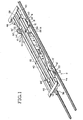
- yaw damper of this invention is particularly suited for, but not limited to, use in the swivelable single axle railcar truck and railcar illustrated in Fig. 1, in which two such trucks (generally referenced by numerals 6 and 8) are used.
- Truck 6 is identical to truck 8 except that it faces the opposite direction, as shown (Fig. 1). Accordingly, for sake of brevity, only truck 8 is illustrated and described in detail, with parts of truck 6 corresponding to those of truck 8 being designated by the same reference numerals, primed.
- truck 8 comprises two parallel damper ramp supports 10 and 12 that are connected together by a transverse tie assembly 14.
- Two independently movable radius arms 16 and 18 are respectively pivoted from the damper ramp supports for supporting a single wheeled axle 20 spaced from and in parallel alignment with assembly 14.
- Two spring elements 22 and 24 respectively act between the radius arms 16 and 18, and an overhead railcar body (generally referenced by -numeral 26) so as to independently spring the radius arms from and provide vertical load bearing support with respect to body 26.
- a swivel assembly 28 is supported by two convergent beams 30 and 32 (Fig. 5) from assembly 14 in overlying relation to axle 20 at two spaced apart vertical load support points adjacent the ends of axle 20.
- the swivel assembly provides horizontal load bearing support with respect to body 26 and a vertical rotational axis about which truck 8 can move rotatively when negotiating curved track.
- this rotational truck axis intersects axle 20.
- Two yaw control assemblies 34 and 36 respectively act between damper ramp supports 10 and 12 and body 26 for controlling- horizontal shifting of the damper ramp supports with respect to body 26 in response to rotative movement of truck about the rotational truck axis when negotiating curved track.
- the railcar is particularly suited for, but is not limited to, use as a container-on-flatcar (COFC) or a trailer-on-flatcar (TOFC) designed to carry either a single container or a single trailer between 45 and 50 feet in length.
- COFC container-on-flatcar
- TOFC trailer-on-flatcar
- Several such railcars may be formulated into multi-unit trains in which they are articulated together, or may be connected by conventional couplers and employed as single unit railway cars.
- the railcar is or may be suited for either usage, although it is depicted as having a conventional coupler 38 at the end supported by truck 6.
- Body 26 is made up of two parallel, closely spaced apart I-beams 40 and 42 that extend substantially its entire length, and respectively support outboard deck sections 44, 46, 48 and 50 adjacent their ends.
- each of these deck sections is identical. Accordingly, for sake of brevity, only section 50 is shown in detail and described with reference numerals; however, corresponding parts of section 48, to the extent illustrated in Fig. 1, are designated by the same reference numerals, primed.
- Figs. 2-4 the portion of section 50 that overlies the outboard end of axle 20 is reinforced by two box beams 52 and 54 that project perpendicularly from I-beam 42 in an outboard direction. These beams are parallel to, but are spaced apart over, opposite sides of axle 20 so that they generally straddle axle 20 when in its centered position illustrated.
- Another box beam 56 extends between and is supported by beams 52 and 54 generally in overlying alignment with radius arm 18.
- a spring platen 57 is secured to and underlies beam 56, as shown ( F ig. 4). This provides reinforcement for the transmission of vertical loads between body.26 and spring element 24, as will be described presently. Spaced from this reinforced portion, the carbody is further reinforced, but to a lesser degree, for operation with assembly 36. This reinforcement is provided by a box beam 58 that projects from I-beam 42, along with two L-beams 60 and 62 that extend between and are supported by beams 58 and 54. Beams 60 and 62 are parallel to and generally spaced apart above the sides of the damper ramp support 12, as shown (Fig. 3).
- Damper ramp support 12 may be of cast or welded construction. In the example, it is of cast construction and is made up of a web reinforced body 64 having a center institutional web 66 and multiple transverse webs 68 of both horizontal and vertical despositions. One end of body 64 forms a web- reinforced journal portion 70 that provides the pivotal support for radius arm 18. The other end of body 64 forms a friction surface 72 (Fig. 2) of suitable composition. This surface cooperates with a damping element carried by radius arm 18 to damp movement of radius arm 18, as will be described presently.
- Body 64 further includes four transversely projecting vertical tabs 74 and two transversely projecting horizontal tabs 76 that extend the length of the body, each of which projects from one of the webs 66, 68. These tabs are symmetrically disposed so that the same body casting can be used either for damper ramp support 10 or damper ramp support 12.
- the transverse tie assembly 14 is made up of two spaced apart, parallel C-beams 78 and 80 that open toward one another. In the example, these beams are secured at their ends to tabs 74 and identical tabs not shown formed by damper ramp support 10. Assembly 14 further includes an elongated strip-like member 82 that extends between beams 78 and 80 and is secured at its ends to tabs 76 and identical tabs not shown formed by damper ramp support 10. This member provides torsional stiffness to assembly 14 that resists rotative shifting of the damper ramp support 10 and 12 about a transverse axis through it. The amount of this stiffness should be sufficient to permit the damper ramp support to shift somewhat about this axis in respective vertical planes in order to accommodate the effects of irregularities in track joints, track spacing and other track conditions that may affect the dynamic behavior of the truck.
- assembly 28 acts between the convergent ends of beams 30 and 32 and I-beams 40 and 42.
- assembly 28 includes a center bowl 84. and a king pin 85.
- Center bowl 84 is mounted by a flange 86 between the inboard flanges of I-beams 40 and 42 by welded lap joints 87.
- Center bowl 84 includes an elastomeric spring ring 88 that is force fit within a cylindrical housing 90 by a shim 92.
- Flange 86 projects transversely from the exterior of housing 90.
- King pin 85 includes a lower annular flange 94 that is secured to center webs 96 of both beams 40 and 42, as shown (Fig. 3).
- King pin 85 projects upwardly from flange 94 and extends coaxially into and through spring ring 88, with which it is engaged by the force produced by shim 92.
- the truck is rotatively moveable about a vertical axis of rotation through the king pin.
- Such movement is resisted, however, by resilient shear forces set up within spring ring 88 in proportion to the extent of the rotational deflection obtained.
- Spring ring 88 thus acts as a source of self-centering force that tends to urge the truck toward a central position corresponding that normally encountered when the truck is traversing straight track.
- This self-centering force is controllable by appropriate selection of the construction of the spring ring. In one presently preferred embodiment of the present invention, however, additional self-centering force is desired, so the truck is equipped with yaw dampers to be described presently.
- each of the yaw control assemblies 34 and 36 includes a yaw damper that provides both frictional damping and self-centering forces.
- a yaw damper that provides both frictional damping and self-centering forces.
- assemblies 34 and 36 are relatively small as compared to the full weight of carbody 26.
- assemblies 34 and 36 allow relative sliding movement between parts mounted by the carbody 26 and truck 8, as will now be described.
- assembly 36 comprises an elongated member 100 forming an upper planar surface and a lower planar surface, both extending in horizontal parallel alignment with the general direction of straight line truck travel.
- Assembly 36 further includes a fixed upper member 98 that is mounted by body 26 in sliding load transmitting relation with the upper surface of member 100, and a lower yaw damper (generally referred by numeral 104) also mounted by body 26.
- the upper and lower surfaces of member 100 are compressively gripped between member 98 and yaw damper 104 such that a frictional damping force is applied to at least one of these surfaces, preferably the lower one, as they move away from the general direction of straight line truck travel when the truck negotiates curved track.
- Member 98 is mounted by the carbody 26 beneath the reinforced portion bounded by beams 60 and 62, generally in overlying relation with damper ramp support 12.
- This member forms a planar surface 102 having a low coefficient of static friction and a relatively higher coefficient of dynamic friction, preferably twice the coefficient of static friction.
- This surface slidably bears down upon the upper surface of member 100.
- Member 100 is formed as an elongated strip-like member of generally inverted U-shaped configuration. As most clearly shown in Fig. 2, member 100 is secured at one end to the upper face of damper ramp support 12, and at its other end to the end of damper ramp support 12 adjacent portion 70, so that it extends essentially along the length of damper ramp support 12.
- the upper and lower surfaces at member 100 extend in parallel alignment with the length at damper ramp support 12, and hence with the general direction of straight line truck travel when the truck negotiates straight track.
- the lower surface of member 100 slidably bears down upon yaw damper 104.
- yaw damper 104 is made up of channel member 106 and a shear/compression spring 108.
- Member 106 is transverse to and underlies member 100, and is secured at its ends by spot welds or the like to the carbody 26, as shown (Fig. 3).
- Member 106 includes a depressed midsection that supports spring 108 so that it is precompressed a predetermined amount against the lower surface of member 100.
- spring 108 includes two bonded end plates 110 and 112 that respectively bear against the lower surface of member 100 and the midsection of member 106, as shown (Fig. 3).
- Member 100 therefore is supported on spring 108 and is effectively gripped between spring 108 and surface 102 in response to the compression force set up in spring 108.
- the frictional damping force obtained is proportional to the resultant of the downward force applied by carbody 26 at surface 102 and the upward normal force exerted by spring 108 against the lower surface of member 100.
- yaw damper 104 This force is controllable in relation to the deflection of spring 108 caused by shifting of member 100 away from the neutral or center position it normally occupies when the truck is in straight line travel. Unlike conventional load responsive yaw dampers, it is possible to control this force so that the frictional damping force obtained remains substantially constant under these conditions. This is accomplished by causing spring 108 to be deflected transversely in shear, as depicted in broken lines in Fig. 3, in response to shifting of member 100 as the truck negotiates a track section having a curvature that tends to cause increased force loading on yaw damper 104. In the example illustrated in Fig.
- spring 108 is depicted in shear on exaggerated scale for clarity, as it would appear when truck 8 negotiates a track section that curves to the left, with truck 8 the lead truck. As it is thus deflected, spring 108 tends to thin down and therefore exerts less compression force upon the lower surface of member 100. During this time, however, the cornering conditions experienced by the truck are such that the downward force appearing at surface 102 has increased. By selecting an appropriate spring construction, this reduction in spring force offsets the increase in downward force so that the frictional damping force obtained remains substantially constant, both during and after the time the truck negotiates the curved track section. As will be appreciated, similar but oppositely acting effects are obtained when the cornering conditions produce a decrease in downward force at surface 102.
- yaw dampers or centering devices could be used in place of or in addition to swivel assembly 28 and yaw control assemblies 34 and 36; however, to the extent these introduce load sensitivities in the damping forces obtained, performance of the truck may be degraded from that attainable with the presently preferred construction.
- yaw control assemblies 34 and 36 could act as guides only, guiding the truck as it swivels without application of any frictional damping force.
- spring 100 could be eliminated or its effects limited to providing requisite support for member 100.
- the yaw damper illustrated in Figs. 6 and 7 may be used in place of yaw damper 104 to provide load proportional frictional damping.
- This yaw damper is generally similar to yaw damper 104, except that the elastomeric spring is not deflected in shear and hence neither thins down nor exerts a self-centering force.
- Parts of the Figs. 6 and 7 yaw damper corresponding to those of yaw damper 104 are not described further, but are designated by the same reference numerals, primed.
- channel member 106' supports an elastomeric compression spring 208 which, like spring 108, is precompressed and exerts a predetermined normal force against the lower surface of member 100'.
- a plate 210 is interposed between spring 208 and member 100'. Plate 210 is not secured to spring 208. This plate includes a low friction surface 212 identical to surface 102 that is in face-to-face contact with the lower surface of member 100. Plate 210 therefore is free to shift with respect to member 100 and likewise permits member 100 to shift with respect to spring 208.
- End plates 214 and 216 enclose the ends of member 106' to maintain spring 208 in a fixed position within the channel.
- the swivelable single axle truck of this invention includes two independently damped suspension assemblies that are respectively operable with radius arms 16 and 18. These suspension assemblies are identical and, as in the case of the other identical assemblies described previously, only one, the suspension assembly associated with radius arm 18 (generally referenced in Figs. 2 and 4 by numeral 114) is shown in detail and described with reference numerals.
- spring element 24 is in the form of an elastomeric rod spring that is compressable transversely between upper platen 57 described previously, and a lower platen 116 formed by a force resolving wedge 118.
- This wedge is carried by the end of radius arm 18 in overlying relation to the end of the axle, and is movable within a guide channel formed by the radius arm for movement toward and perpendicular to surface 72 in response to application of a force normal to surface 72.
- a frictional damper 120 is supported by pivot 121 from the thick end of wedge 118, by which it is urged in a normal direction against surface 72.
- Two guide plates 122 are respectively upstanding from the sides of surface 72 to engage and maintain damper 120 in alignment with surface 72 as the end of radius arm 18 pivots vertically.
- wedge 118 resolves a component of the compressive force on spring element 24 into a normal force urging damper 120 into engagement with surface 72.
- the frictional damping force obtained will vary in accordance with this normal force and therefore is proportional to the vertical load applied to spring element 24.
- a brake assembly 124 is mounted by the lower inboard end of radius arm 18. As illustrated in Fig. 2, this assembly includes an open ended mounting channel 126 that opens at one end opposite the wheel flange. A brake member 128 is movable within this channel by an appropriate actuator not shown so as to apply braking effort to the wheel tread. An elastomer- ically damped adaptor assembly 130 supports axle 20 from the outboard end of radius arm 18. Further details of these and other aspects of the suspension, brake or adaptor assemblies are illustrated and described in the aforesaid U.S. Patent No. 4,356,775.
Abstract
Description
- This invention relates to railcars and, more particularly, to dampers suitable for use to control yaw in swivelable railcar trucks. The invention is illustrated and described herein for application to swivelable single axle railcar trucks; however, the invention is not limited to this application and may be used with double axle, triple axle and other types of swivelable trucks or bogies.
- A principal object of this invention is to provide an improved yaw damper for a swivelable railcar truck, whether single axle, double axle, triple axle or other construction.
- Another object of this invention is to provide a yaw damper for a swivelable railcar truck that applies a frictional damping force when the truck negotiates curved track.
- A related object of this invention is to control the frictional damping force obtained so that it can provide multiple truck control functions.
- Still another object of this invention is to provide a yaw damper especially suited for use with the swivelable single axle railcar truck disclosed herein.
- These objects are accomplished in accordance with the principles of this invention by providing a yaw damper that comprises an elongated member or other means movable conjointly with a swivelable railcar truck. This member forms general direction of straight line truck travel. A yaw control assembly mountable by an overhead carbody compressively grips these surfaces to apply a frictional damping force to at least one of these surfaces as they move away from the general direction of straight line truck travel when the truck negotiates curved track. According to further aspects of this invention, the yaw control assembly includes a yaw damper that provides either a damping force or both a damping force and a self-centering force in response to such movement of the truck.
- These and other features, objects and advantages of the present invention will become apparent from the detailed description and claims to follow, taken in conjunction with accompanying drawings in which like parts bear like reference numerals.
-
- Fig. 1 is a perspective of a railcar equipped with two swivelable single axle railcar trucks, each including two of the presently preferred yaw dampers according to this invention, with part of the railcar body broken away;
- Fig. 2 is a section taken along the line 2-2 in Fig. 1;
- Fig. 3 is a section taken along the line 3-3 in Fig. 2;
- Fig. 4 is a section taken along the line 4-4 in Fig. 2;
- Fig. 5 is a section taken along the line 5-5 in Fig. 3;
- Fig. 6 is a side elevation of another presently preferred embodiment of the yaw damper of this invention;
- Fig. 7 is a section taken along the line 7-7 in Fig. 6.
- One presently preferred embodiment of the yaw damper of this invention is particularly suited for, but not limited to, use in the swivelable single axle railcar truck and railcar illustrated in Fig. 1, in which two such trucks (generally referenced by
numerals 6 and 8) are used.Truck 6 is identical totruck 8 except that it faces the opposite direction, as shown (Fig. 1). Accordingly, for sake of brevity, onlytruck 8 is illustrated and described in detail, with parts oftruck 6 corresponding to those oftruck 8 being designated by the same reference numerals, primed. - As illustrated in Fig. 1,
truck 8 comprises two parallel damper ramp supports 10 and 12 that are connected together by atransverse tie assembly 14. Two independentlymovable radius arms wheeled axle 20 spaced from and in parallel alignment withassembly 14. Twospring elements radius arms body 26. Aswivel assembly 28 is supported by twoconvergent beams 30 and 32 (Fig. 5) fromassembly 14 in overlying relation toaxle 20 at two spaced apart vertical load support points adjacent the ends ofaxle 20. The swivel assembly provides horizontal load bearing support with respect tobody 26 and a vertical rotational axis about whichtruck 8 can move rotatively when negotiating curved track. In the example illustrated, this rotational truck axis intersectsaxle 20. Two yaw control assemblies 34 and 36 respectively act between damper ramp supports 10 and 12 andbody 26 for controlling- horizontal shifting of the damper ramp supports with respect tobody 26 in response to rotative movement of truck about the rotational truck axis when negotiating curved track. - In the example illustrated in Fig. 1, the railcar is particularly suited for, but is not limited to, use as a container-on-flatcar (COFC) or a trailer-on-flatcar (TOFC) designed to carry either a single container or a single trailer between 45 and 50 feet in length. Several such railcars may be formulated into multi-unit trains in which they are articulated together, or may be connected by conventional couplers and employed as single unit railway cars. In the example illustrated, the railcar is or may be suited for either usage, although it is depicted as having a
conventional coupler 38 at the end supported bytruck 6.Body 26 is made up of two parallel, closely spaced apart I-beams outboard deck sections - Each of these deck sections is identical. Accordingly, for sake of brevity, only
section 50 is shown in detail and described with reference numerals; however, corresponding parts ofsection 48, to the extent illustrated in Fig. 1, are designated by the same reference numerals, primed. Referring now to Figs. 2-4, the portion ofsection 50 that overlies the outboard end ofaxle 20 is reinforced by twobox beams beam 42 in an outboard direction. These beams are parallel to, but are spaced apart over, opposite sides ofaxle 20 so that they generally straddleaxle 20 when in its centered position illustrated. Anotherbox beam 56 extends between and is supported bybeams radius arm 18. Aspring platen 57 is secured to and underliesbeam 56, as shown (Fig. 4). This provides reinforcement for the transmission of vertical loads between body.26 andspring element 24, as will be described presently. Spaced from this reinforced portion, the carbody is further reinforced, but to a lesser degree, for operation withassembly 36. This reinforcement is provided by abox beam 58 that projects from I-beam 42, along with two L-beams beams Beams damper ramp support 12, as shown (Fig. 3). - Referring now in particular to
truck 8, damper ramp supports 10 and 12 are identical. Accordingly, for sake of brevity, onlydamper ramp support 12 is shown in detail and described with reference numerals. Damperramp support 12 may be of cast or welded construction. In the example, it is of cast construction and is made up of a web reinforcedbody 64 having a centerinstitutional web 66 and multipletransverse webs 68 of both horizontal and vertical despositions. One end ofbody 64 forms a web- reinforcedjournal portion 70 that provides the pivotal support forradius arm 18. The other end ofbody 64 forms a friction surface 72 (Fig. 2) of suitable composition. This surface cooperates with a damping element carried byradius arm 18 to damp movement ofradius arm 18, as will be described presently.Body 64 further includes four transversely projectingvertical tabs 74 and two transversely projectinghorizontal tabs 76 that extend the length of the body, each of which projects from one of thewebs damper ramp support 10 ordamper ramp support 12. - The
transverse tie assembly 14 is made up of two spaced apart, parallel C-beams tabs 74 and identical tabs not shown formed bydamper ramp support 10.Assembly 14 further includes an elongated strip-like member 82 that extends betweenbeams tabs 76 and identical tabs not shown formed bydamper ramp support 10. This member provides torsional stiffness toassembly 14 that resists rotative shifting of the damper ramp support 10 and 12 about a transverse axis through it. The amount of this stiffness should be sufficient to permit the damper ramp support to shift somewhat about this axis in respective vertical planes in order to accommodate the effects of irregularities in track joints, track spacing and other track conditions that may affect the dynamic behavior of the truck. - The
swivel assembly 28 acts between the convergent ends ofbeams beams assembly 28 includes acenter bowl 84. and aking pin 85.Center bowl 84 is mounted by aflange 86 between the inboard flanges of I-beams welded lap joints 87.Center bowl 84 includes anelastomeric spring ring 88 that is force fit within acylindrical housing 90 by ashim 92.Flange 86 projects transversely from the exterior ofhousing 90.King pin 85 includes a lowerannular flange 94 that is secured to centerwebs 96 of bothbeams King pin 85 projects upwardly fromflange 94 and extends coaxially into and throughspring ring 88, with which it is engaged by the force produced byshim 92. - Consequently, the truck is rotatively moveable about a vertical axis of rotation through the king pin. Such movement is resisted, however, by resilient shear forces set up within
spring ring 88 in proportion to the extent of the rotational deflection obtained.Spring ring 88 thus acts as a source of self-centering force that tends to urge the truck toward a central position corresponding that normally encountered when the truck is traversing straight track. This self-centering force is controllable by appropriate selection of the construction of the spring ring. In one presently preferred embodiment of the present invention, however, additional self-centering force is desired, so the truck is equipped with yaw dampers to be described presently. As will be recognized, of course, this may or may not be desirable in all applications, in which a conventional non-sprung swivel assembly could be used in place ofswivel assembly 28. In this case, the self-centering force, if any, could be provided by any, some or all of the foregoing, or otherwise. - In one presently preferred embodiment of the swivelable single axle truck of this invention, each of the
yaw control assemblies spring elements assemblies carbody 26. As a consequence,assemblies truck 8, as will now be described. - The
yaw control assemblies assembly 36 is shown in detail and described with reference numerals. Referring now in particular to Figs. 2 and 3,assembly 36 comprises anelongated member 100 forming an upper planar surface and a lower planar surface, both extending in horizontal parallel alignment with the general direction of straight line truck travel.Assembly 36 further includes a fixedupper member 98 that is mounted bybody 26 in sliding load transmitting relation with the upper surface ofmember 100, and a lower yaw damper (generally referred by numeral 104) also mounted bybody 26. The upper and lower surfaces ofmember 100 are compressively gripped betweenmember 98 andyaw damper 104 such that a frictional damping force is applied to at least one of these surfaces, preferably the lower one, as they move away from the general direction of straight line truck travel when the truck negotiates curved track. -
Member 98 is mounted by thecarbody 26 beneath the reinforced portion bounded bybeams damper ramp support 12. This member forms aplanar surface 102 having a low coefficient of static friction and a relatively higher coefficient of dynamic friction, preferably twice the coefficient of static friction. This surface slidably bears down upon the upper surface ofmember 100.Member 100 is formed as an elongated strip-like member of generally inverted U-shaped configuration. As most clearly shown in Fig. 2,member 100 is secured at one end to the upper face ofdamper ramp support 12, and at its other end to the end ofdamper ramp support 12adjacent portion 70, so that it extends essentially along the length ofdamper ramp support 12. The upper and lower surfaces atmember 100 extend in parallel alignment with the length atdamper ramp support 12, and hence with the general direction of straight line truck travel when the truck negotiates straight track. The lower surface ofmember 100 slidably bears down uponyaw damper 104. - Still referring to Figs. 2 and 3,
yaw damper 104 is made up ofchannel member 106 and a shear/compression spring 108.Member 106 is transverse to and underliesmember 100, and is secured at its ends by spot welds or the like to thecarbody 26, as shown (Fig. 3).Member 106 includes a depressed midsection that supportsspring 108 so that it is precompressed a predetermined amount against the lower surface ofmember 100. In the example,spring 108 includes two bondedend plates 110 and 112 that respectively bear against the lower surface ofmember 100 and the midsection ofmember 106, as shown (Fig. 3).Member 100 therefore is supported onspring 108 and is effectively gripped betweenspring 108 andsurface 102 in response to the compression force set up inspring 108. As a consequence, the frictional damping force obtained is proportional to the resultant of the downward force applied by carbody 26 atsurface 102 and the upward normal force exerted byspring 108 against the lower surface ofmember 100. - An important aspect of
yaw damper 104 is that this force is controllable in relation to the deflection ofspring 108 caused by shifting ofmember 100 away from the neutral or center position it normally occupies when the truck is in straight line travel. Unlike conventional load responsive yaw dampers, it is possible to control this force so that the frictional damping force obtained remains substantially constant under these conditions. This is accomplished by causingspring 108 to be deflected transversely in shear, as depicted in broken lines in Fig. 3, in response to shifting ofmember 100 as the truck negotiates a track section having a curvature that tends to cause increased force loading onyaw damper 104. In the example illustrated in Fig. 3,spring 108 is depicted in shear on exaggerated scale for clarity, as it would appear whentruck 8 negotiates a track section that curves to the left, withtruck 8 the lead truck. As it is thus deflected,spring 108 tends to thin down and therefore exerts less compression force upon the lower surface ofmember 100. During this time, however, the cornering conditions experienced by the truck are such that the downward force appearing atsurface 102 has increased. By selecting an appropriate spring construction, this reduction in spring force offsets the increase in downward force so that the frictional damping force obtained remains substantially constant, both during and after the time the truck negotiates the curved track section. As will be appreciated, similar but oppositely acting effects are obtained when the cornering conditions produce a decrease in downward force atsurface 102. - Thus it is possible, by appropriate selection of spring construction, to control the occurrance of this "thinning" effect in relation to shifting of
member 100 so that the frictional damping force obtained remains substantially constant throughout the range of truck rotation, regardless of loading conditions. As will now be appreciated, oncespring 100 is so deflected, it continuously applies a shear restoring force, seeking to return to its normal condition of essentially sole compression deflection illustrated in solid lines in Fig. 3. This of course produces a force on the lower surface offorce member 100 that urges the truck back to a normally centered position. It will be recognized, of course, that conventional yaw dampers or centering devices could be used in place of or in addition to swivelassembly 28 andyaw control assemblies yaw control assemblies spring 100 could be eliminated or its effects limited to providing requisite support formember 100. - In those instances where sufficient self-centering force is obtained from the swivel assembly or otherwise, and where it is not a requirement to provide substantially constant frictional damping forces as just described, the yaw damper illustrated in Figs. 6 and 7 may be used in place of
yaw damper 104 to provide load proportional frictional damping. This yaw damper is generally similar toyaw damper 104, except that the elastomeric spring is not deflected in shear and hence neither thins down nor exerts a self-centering force. Parts of the Figs. 6 and 7 yaw damper corresponding to those ofyaw damper 104 are not described further, but are designated by the same reference numerals, primed. - Still referring to Figs. 6 and 7, channel member 106' supports an
elastomeric compression spring 208 which, likespring 108, is precompressed and exerts a predetermined normal force against the lower surface of member 100'. Unlikeyaw damper 104, however, aplate 210 is interposed betweenspring 208 and member 100'.Plate 210 is not secured tospring 208. This plate includes alow friction surface 212 identical to surface 102 that is in face-to-face contact with the lower surface ofmember 100.Plate 210 therefore is free to shift with respect tomember 100 and likewise permitsmember 100 to shift with respect tospring 208. To the extent stick-slip or like conditions atsurface 212 produce transverse forces in response to shifting of member 100', some conjoint movement ofplate 210 may occur, with attendant shear forces being transmitted tospring 208. These forces, however, should be small in magnitude as compared to those set up inspring 108, and should be dissipated by subsequent shifting ofplate 210 developed on account of its being allowed to "float" with respect tospring 208. Consequently,spring 208 is subjected essentially only to compressive loads, and hence the frictional damping force obtained may vary in proportion to such loads, with little, if any, of the effects of shear loading/deflection attainable withyaw damper 104.End plates spring 208 in a fixed position within the channel. An advantage of the Fig. 6 and 7 yaw damper andyaw damper 104 is that both are self compensating for wear in that, as their respective friction surfaces are worn away, the elastomeric spring continually urges the friction surfaces into frictional engagement. - In the example illustrated, the swivelable single axle truck of this invention includes two independently damped suspension assemblies that are respectively operable with
radius arms spring element 24 is in the form of an elastomeric rod spring that is compressable transversely betweenupper platen 57 described previously, and alower platen 116 formed by aforce resolving wedge 118. This wedge is carried by the end ofradius arm 18 in overlying relation to the end of the axle, and is movable within a guide channel formed by the radius arm for movement toward and perpendicular to surface 72 in response to application of a force normal to surface 72. Africtional damper 120 is supported bypivot 121 from the thick end ofwedge 118, by which it is urged in a normal direction against surface 72. Twoguide plates 122 are respectively upstanding from the sides of surface 72 to engage and maintaindamper 120 in alignment with surface 72 as the end ofradius arm 18 pivots vertically. In operation, as the radius arm pivots vertically,wedge 118 resolves a component of the compressive force onspring element 24 into a normalforce urging damper 120 into engagement with surface 72. As will be appreciated, the frictional damping force obtained will vary in accordance with this normal force and therefore is proportional to the vertical load applied tospring element 24. - According to still further aspects of the swivelable single axle truck of this invention, a
brake assembly 124 is mounted by the lower inboard end ofradius arm 18. As illustrated in Fig. 2, this assembly includes an open ended mountingchannel 126 that opens at one end opposite the wheel flange. Abrake member 128 is movable within this channel by an appropriate actuator not shown so as to apply braking effort to the wheel tread. An elastomer- ically dampedadaptor assembly 130 supportsaxle 20 from the outboard end ofradius arm 18. Further details of these and other aspects of the suspension, brake or adaptor assemblies are illustrated and described in the aforesaid U.S. Patent No. 4,356,775. - Although one presently preferred embodiment of the present invention has been illustrated and described herein, variations will become apparent to one of ordinary . skill in the art. Accordingly, the invention is not to be limited to the specific embodiment illustrated and described herein, and the true scope and spirit of the invention are to be determined by reference to the appended claims.
Claims (12)
Priority Applications (1)
| Application Number | Priority Date | Filing Date | Title |
|---|---|---|---|
| AT86101521T ATE58686T1 (en) | 1985-02-08 | 1986-02-06 | YAW DAMPER FOR SWIVELING BOGIES OF RAIL VEHICLES. |
Applications Claiming Priority (2)
| Application Number | Priority Date | Filing Date | Title |
|---|---|---|---|
| US06/699,740 US4596194A (en) | 1985-02-08 | 1985-02-08 | Yaw damper for swivelable railcar trucks |
| US699740 | 1985-02-08 |
Publications (3)
| Publication Number | Publication Date |
|---|---|
| EP0190752A2 true EP0190752A2 (en) | 1986-08-13 |
| EP0190752A3 EP0190752A3 (en) | 1987-06-16 |
| EP0190752B1 EP0190752B1 (en) | 1990-11-28 |
Family
ID=24810695
Family Applications (1)
| Application Number | Title | Priority Date | Filing Date |
|---|---|---|---|
| EP86101521A Expired - Lifetime EP0190752B1 (en) | 1985-02-08 | 1986-02-06 | Yaw damper for swivelable railcar trucks |
Country Status (11)
| Country | Link |
|---|---|
| US (1) | US4596194A (en) |
| EP (1) | EP0190752B1 (en) |
| JP (1) | JPS61247562A (en) |
| KR (1) | KR860006376A (en) |
| CN (1) | CN86101088B (en) |
| AT (1) | ATE58686T1 (en) |
| AU (1) | AU577923B2 (en) |
| CA (1) | CA1281940C (en) |
| DE (1) | DE3675785D1 (en) |
| ES (1) | ES8701083A1 (en) |
| MX (1) | MX162432A (en) |
Families Citing this family (8)
| Publication number | Priority date | Publication date | Assignee | Title |
|---|---|---|---|---|
| US5246242A (en) * | 1990-10-05 | 1993-09-21 | Paccar Inc. | Passively steered tandem axle group |
| CN101541613B (en) * | 2006-11-20 | 2012-07-04 | 电动内燃机公司 | Cab isolation system for locomotive |
| FR2987590B1 (en) * | 2012-03-05 | 2014-11-28 | Alstom Transport Sa | BOGIE PENDULAIRE FOR RAILWAY VEHICLE, VEHICLE AND CORRESPONDING TRAIN |
| US9403542B2 (en) | 2013-08-08 | 2016-08-02 | Mammoet Usa South, Inc. | Rail car |
| CN106394145B (en) * | 2016-11-18 | 2019-05-24 | 中车四方车辆有限公司 | Double dynamical guiding running gear and road rail vehicle |
| CN106553492A (en) * | 2016-11-18 | 2017-04-05 | 中车四方车辆有限公司 | Railway guider and autorail |
| CN106515328B (en) * | 2016-11-18 | 2020-04-10 | 中车四方车辆有限公司 | Rubber wheel driven road-rail dual-purpose vehicle |
| JP6936572B2 (en) * | 2016-11-21 | 2021-09-15 | 三菱重工エンジニアリング株式会社 | Track vehicle |
Citations (13)
| Publication number | Priority date | Publication date | Assignee | Title |
|---|---|---|---|---|
| US2680413A (en) * | 1951-03-13 | 1954-06-08 | Becker Anton | Load-stabilizing linkage for metallic cars |
| US2728305A (en) * | 1950-02-02 | 1955-12-27 | Pullman Standard Car Mfg Co | Railway car underframe support |
| US3518948A (en) * | 1966-04-26 | 1970-07-07 | British Railways Board | Railway trucks with elastomeric biased side bearings |
| US3687085A (en) * | 1969-10-13 | 1972-08-29 | British Railways Board | Lateral motion truck |
| US3690271A (en) * | 1968-09-17 | 1972-09-12 | British Railways Board | Dampened railway car truck |
| US3693553A (en) * | 1970-03-03 | 1972-09-26 | Gen Steel Ind Inc | Motorized railway locomotive truck |
| GB1309637A (en) * | 1969-05-13 | 1973-03-14 | Gloucester Railway Carriage | Railway vehicles |
| US3777672A (en) * | 1970-12-19 | 1973-12-11 | Rheinstahl Ag | Railway car suspension |
| US3910655A (en) * | 1974-04-01 | 1975-10-07 | Midland Ross Corp | Constant contact side bearing |
| US4134343A (en) * | 1976-09-27 | 1979-01-16 | General Steel Industries, Inc. | Radial axle railway truck |
| US4282816A (en) * | 1978-06-10 | 1981-08-11 | Dunlop Limited | Elastomeric railway suspension |
| EP0054760A1 (en) * | 1980-12-17 | 1982-06-30 | Hoesch Aktiengesellschaft | Bearing for bogies of railway vehicles |
| US4356775A (en) * | 1978-01-18 | 1982-11-02 | H. Neil Paton | Damped railway car suspension |
Family Cites Families (1)
| Publication number | Priority date | Publication date | Assignee | Title |
|---|---|---|---|---|
| US1309637A (en) * | 1919-07-15 | Gyro apparatus |
-
1985
- 1985-02-08 US US06/699,740 patent/US4596194A/en not_active Expired - Fee Related
-
1986
- 1986-01-30 CN CN86101088A patent/CN86101088B/en not_active Expired
- 1986-02-05 CA CA000501169A patent/CA1281940C/en not_active Expired - Lifetime
- 1986-02-06 JP JP61023062A patent/JPS61247562A/en active Pending
- 1986-02-06 DE DE8686101521T patent/DE3675785D1/en not_active Expired - Lifetime
- 1986-02-06 AT AT86101521T patent/ATE58686T1/en active
- 1986-02-06 EP EP86101521A patent/EP0190752B1/en not_active Expired - Lifetime
- 1986-02-06 KR KR1019860000829A patent/KR860006376A/en not_active Application Discontinuation
- 1986-02-07 AU AU53300/86A patent/AU577923B2/en not_active Ceased
- 1986-02-07 MX MX1482A patent/MX162432A/en unknown
- 1986-02-07 ES ES551774A patent/ES8701083A1/en not_active Expired
Patent Citations (13)
| Publication number | Priority date | Publication date | Assignee | Title |
|---|---|---|---|---|
| US2728305A (en) * | 1950-02-02 | 1955-12-27 | Pullman Standard Car Mfg Co | Railway car underframe support |
| US2680413A (en) * | 1951-03-13 | 1954-06-08 | Becker Anton | Load-stabilizing linkage for metallic cars |
| US3518948A (en) * | 1966-04-26 | 1970-07-07 | British Railways Board | Railway trucks with elastomeric biased side bearings |
| US3690271A (en) * | 1968-09-17 | 1972-09-12 | British Railways Board | Dampened railway car truck |
| GB1309637A (en) * | 1969-05-13 | 1973-03-14 | Gloucester Railway Carriage | Railway vehicles |
| US3687085A (en) * | 1969-10-13 | 1972-08-29 | British Railways Board | Lateral motion truck |
| US3693553A (en) * | 1970-03-03 | 1972-09-26 | Gen Steel Ind Inc | Motorized railway locomotive truck |
| US3777672A (en) * | 1970-12-19 | 1973-12-11 | Rheinstahl Ag | Railway car suspension |
| US3910655A (en) * | 1974-04-01 | 1975-10-07 | Midland Ross Corp | Constant contact side bearing |
| US4134343A (en) * | 1976-09-27 | 1979-01-16 | General Steel Industries, Inc. | Radial axle railway truck |
| US4356775A (en) * | 1978-01-18 | 1982-11-02 | H. Neil Paton | Damped railway car suspension |
| US4282816A (en) * | 1978-06-10 | 1981-08-11 | Dunlop Limited | Elastomeric railway suspension |
| EP0054760A1 (en) * | 1980-12-17 | 1982-06-30 | Hoesch Aktiengesellschaft | Bearing for bogies of railway vehicles |
Also Published As
| Publication number | Publication date |
|---|---|
| MX162432A (en) | 1991-05-10 |
| AU577923B2 (en) | 1988-10-06 |
| CN86101088A (en) | 1986-08-06 |
| ATE58686T1 (en) | 1990-12-15 |
| ES551774A0 (en) | 1986-11-16 |
| KR860006376A (en) | 1986-09-09 |
| ES8701083A1 (en) | 1986-11-16 |
| AU5330086A (en) | 1986-08-14 |
| EP0190752B1 (en) | 1990-11-28 |
| CA1281940C (en) | 1991-03-26 |
| JPS61247562A (en) | 1986-11-04 |
| US4596194A (en) | 1986-06-24 |
| DE3675785D1 (en) | 1991-01-10 |
| CN86101088B (en) | 1988-07-27 |
| EP0190752A3 (en) | 1987-06-16 |
Similar Documents
| Publication | Publication Date | Title |
|---|---|---|
| US4003316A (en) | Articulated railway car trucks | |
| US4134343A (en) | Radial axle railway truck | |
| US4455946A (en) | Articulated trucks | |
| US4131069A (en) | Articulated railway car trucks | |
| US4480553A (en) | Stabilized railway vehicle | |
| US4356775A (en) | Damped railway car suspension | |
| US4151801A (en) | Self-steering railway truck | |
| US4244297A (en) | Articulated railway car trucks | |
| US4483253A (en) | Flexible railway car truck | |
| US5138954A (en) | Freight railcar truck and bolster for outboard support of car body with side bearings located entirely outside of the sideframes for receiving the entire vehicle weight | |
| CA1071026A (en) | Railway vehicle suspension | |
| US4655143A (en) | Articulated trucks | |
| US5174218A (en) | Self-steering trucks with side bearings supporting the entire weight of the vehicle | |
| US4237791A (en) | Radial axle railway truck disc brakes | |
| US5438934A (en) | Lightweight, improved performance truck | |
| US4596194A (en) | Yaw damper for swivelable railcar trucks | |
| CA2046826C (en) | Multi friction side bearing for a railcar truck | |
| US4352509A (en) | Damped rubber tired vehicle suspension | |
| US5647283A (en) | Railway truck and steering apparatus therefor | |
| US4428301A (en) | Radial axle railway truck | |
| EP0190751B1 (en) | Swivelable single axle railcar truck and railcar | |
| US4781124A (en) | Articulated trucks | |
| US4889054A (en) | Steering arms for self-steering trucks and truck retrofitting method | |
| CA1065190A (en) | Articulated trucks | |
| US4817535A (en) | Stand alone well car with double axle suspension system |
Legal Events
| Date | Code | Title | Description |
|---|---|---|---|
| PUAI | Public reference made under article 153(3) epc to a published international application that has entered the european phase |
Free format text: ORIGINAL CODE: 0009012 |
|
| AK | Designated contracting states |
Kind code of ref document: A2 Designated state(s): AT BE CH DE FR GB IT LI LU NL SE |
|
| PUAL | Search report despatched |
Free format text: ORIGINAL CODE: 0009013 |
|
| RHK1 | Main classification (correction) |
Ipc: B61F 5/24 |
|
| AK | Designated contracting states |
Kind code of ref document: A3 Designated state(s): AT BE CH DE FR GB IT LI LU NL SE |
|
| 17P | Request for examination filed |
Effective date: 19871120 |
|
| 17Q | First examination report despatched |
Effective date: 19890202 |
|
| GRAA | (expected) grant |
Free format text: ORIGINAL CODE: 0009210 |
|
| AK | Designated contracting states |
Kind code of ref document: B1 Designated state(s): AT BE CH DE FR GB IT LI LU NL SE |
|
| PG25 | Lapsed in a contracting state [announced via postgrant information from national office to epo] |
Ref country code: SE Effective date: 19901128 Ref country code: NL Effective date: 19901128 Ref country code: LI Effective date: 19901128 Ref country code: CH Effective date: 19901128 Ref country code: AT Effective date: 19901128 |
|
| REF | Corresponds to: |
Ref document number: 58686 Country of ref document: AT Date of ref document: 19901215 Kind code of ref document: T |
|
| ITF | It: translation for a ep patent filed |
Owner name: ING. A. GIAMBROCONO & C. S.R.L. |
|
| ET | Fr: translation filed | ||
| REF | Corresponds to: |
Ref document number: 3675785 Country of ref document: DE Date of ref document: 19910110 |
|
| ITTA | It: last paid annual fee | ||
| PG25 | Lapsed in a contracting state [announced via postgrant information from national office to epo] |
Ref country code: LU Free format text: LAPSE BECAUSE OF NON-PAYMENT OF DUE FEES Effective date: 19910228 |
|
| REG | Reference to a national code |
Ref country code: CH Ref legal event code: PL |
|
| NLV1 | Nl: lapsed or annulled due to failure to fulfill the requirements of art. 29p and 29m of the patents act | ||
| PLBE | No opposition filed within time limit |
Free format text: ORIGINAL CODE: 0009261 |
|
| STAA | Information on the status of an ep patent application or granted ep patent |
Free format text: STATUS: NO OPPOSITION FILED WITHIN TIME LIMIT |
|
| 26N | No opposition filed | ||
| PGFP | Annual fee paid to national office [announced via postgrant information from national office to epo] |
Ref country code: GB Payment date: 19940104 Year of fee payment: 9 |
|
| PGFP | Annual fee paid to national office [announced via postgrant information from national office to epo] |
Ref country code: FR Payment date: 19940121 Year of fee payment: 9 |
|
| PGFP | Annual fee paid to national office [announced via postgrant information from national office to epo] |
Ref country code: DE Payment date: 19940124 Year of fee payment: 9 |
|
| PGFP | Annual fee paid to national office [announced via postgrant information from national office to epo] |
Ref country code: BE Payment date: 19940224 Year of fee payment: 9 |
|
| PG25 | Lapsed in a contracting state [announced via postgrant information from national office to epo] |
Ref country code: GB Effective date: 19950206 |
|
| PG25 | Lapsed in a contracting state [announced via postgrant information from national office to epo] |
Ref country code: BE Effective date: 19950228 |
|
| BERE | Be: lapsed |
Owner name: PATON H. NEIL Effective date: 19950228 |
|
| GBPC | Gb: european patent ceased through non-payment of renewal fee |
Effective date: 19950206 |
|
| PG25 | Lapsed in a contracting state [announced via postgrant information from national office to epo] |
Ref country code: FR Effective date: 19951031 |
|
| PG25 | Lapsed in a contracting state [announced via postgrant information from national office to epo] |
Ref country code: DE Effective date: 19951101 |
|
| REG | Reference to a national code |
Ref country code: FR Ref legal event code: ST |
|
| PG25 | Lapsed in a contracting state [announced via postgrant information from national office to epo] |
Ref country code: IT Free format text: LAPSE BECAUSE OF NON-PAYMENT OF DUE FEES;WARNING: LAPSES OF ITALIAN PATENTS WITH EFFECTIVE DATE BEFORE 2007 MAY HAVE OCCURRED AT ANY TIME BEFORE 2007. THE CORRECT EFFECTIVE DATE MAY BE DIFFERENT FROM THE ONE RECORDED. Effective date: 20050206 |