EP0190580B1 - Flap folding apparatus for a disk envelope - Google Patents
Flap folding apparatus for a disk envelope Download PDFInfo
- Publication number
- EP0190580B1 EP0190580B1 EP86100562A EP86100562A EP0190580B1 EP 0190580 B1 EP0190580 B1 EP 0190580B1 EP 86100562 A EP86100562 A EP 86100562A EP 86100562 A EP86100562 A EP 86100562A EP 0190580 B1 EP0190580 B1 EP 0190580B1
- Authority
- EP
- European Patent Office
- Prior art keywords
- folding
- mandrel
- folding blades
- flap
- flaps
- Prior art date
- Legal status (The legal status is an assumption and is not a legal conclusion. Google has not performed a legal analysis and makes no representation as to the accuracy of the status listed.)
- Expired - Lifetime
Links
- 239000000463 material Substances 0.000 claims description 18
- 229920003023 plastic Polymers 0.000 claims description 11
- 239000004033 plastic Substances 0.000 claims description 11
- 238000010438 heat treatment Methods 0.000 claims description 10
- 230000006835 compression Effects 0.000 claims description 9
- 238000007906 compression Methods 0.000 claims description 9
- 229920002457 flexible plastic Polymers 0.000 claims description 7
- 230000007246 mechanism Effects 0.000 description 10
- 238000010586 diagram Methods 0.000 description 9
- 229910000831 Steel Inorganic materials 0.000 description 2
- 230000009471 action Effects 0.000 description 2
- 238000005452 bending Methods 0.000 description 2
- 238000000034 method Methods 0.000 description 2
- 230000008569 process Effects 0.000 description 2
- 239000010959 steel Substances 0.000 description 2
- 238000000137 annealing Methods 0.000 description 1
- 238000004140 cleaning Methods 0.000 description 1
- 238000001816 cooling Methods 0.000 description 1
- 238000005520 cutting process Methods 0.000 description 1
- 230000003247 decreasing effect Effects 0.000 description 1
- 230000000694 effects Effects 0.000 description 1
- 230000006870 function Effects 0.000 description 1
- 238000010409 ironing Methods 0.000 description 1
- 238000004519 manufacturing process Methods 0.000 description 1
- 229920000915 polyvinyl chloride Polymers 0.000 description 1
- 239000004800 polyvinyl chloride Substances 0.000 description 1
- 238000004080 punching Methods 0.000 description 1
- 238000007789 sealing Methods 0.000 description 1
- 230000007704 transition Effects 0.000 description 1
Images


Classifications
-
- G—PHYSICS
- G11—INFORMATION STORAGE
- G11B—INFORMATION STORAGE BASED ON RELATIVE MOVEMENT BETWEEN RECORD CARRIER AND TRANSDUCER
- G11B23/00—Record carriers not specific to the method of recording or reproducing; Accessories, e.g. containers, specially adapted for co-operation with the recording or reproducing apparatus ; Intermediate mediums; Apparatus or processes specially adapted for their manufacture
- G11B23/02—Containers; Storing means both adapted to cooperate with the recording or reproducing means
- G11B23/03—Containers for flat record carriers
- G11B23/0326—Assembling of containers
-
- B—PERFORMING OPERATIONS; TRANSPORTING
- B31—MAKING ARTICLES OF PAPER, CARDBOARD OR MATERIAL WORKED IN A MANNER ANALOGOUS TO PAPER; WORKING PAPER, CARDBOARD OR MATERIAL WORKED IN A MANNER ANALOGOUS TO PAPER
- B31B—MAKING CONTAINERS OF PAPER, CARDBOARD OR MATERIAL WORKED IN A MANNER ANALOGOUS TO PAPER
- B31B2160/00—Shape of flexible containers
- B31B2160/10—Shape of flexible containers rectangular and flat, i.e. without structural provision for thickness of contents
-
- B—PERFORMING OPERATIONS; TRANSPORTING
- B31—MAKING ARTICLES OF PAPER, CARDBOARD OR MATERIAL WORKED IN A MANNER ANALOGOUS TO PAPER; WORKING PAPER, CARDBOARD OR MATERIAL WORKED IN A MANNER ANALOGOUS TO PAPER
- B31B—MAKING CONTAINERS OF PAPER, CARDBOARD OR MATERIAL WORKED IN A MANNER ANALOGOUS TO PAPER
- B31B50/00—Making rigid or semi-rigid containers, e.g. boxes or cartons
- B31B50/26—Folding sheets, blanks or webs
- B31B50/28—Folding sheets, blanks or webs around mandrels, e.g. for forming bottoms
- B31B50/30—Folding sheets, blanks or webs around mandrels, e.g. for forming bottoms the mandrels moving
-
- Y—GENERAL TAGGING OF NEW TECHNOLOGICAL DEVELOPMENTS; GENERAL TAGGING OF CROSS-SECTIONAL TECHNOLOGIES SPANNING OVER SEVERAL SECTIONS OF THE IPC; TECHNICAL SUBJECTS COVERED BY FORMER USPC CROSS-REFERENCE ART COLLECTIONS [XRACs] AND DIGESTS
- Y10—TECHNICAL SUBJECTS COVERED BY FORMER USPC
- Y10S—TECHNICAL SUBJECTS COVERED BY FORMER USPC CROSS-REFERENCE ART COLLECTIONS [XRACs] AND DIGESTS
- Y10S493/00—Manufacturing container or tube from paper; or other manufacturing from a sheet or web
- Y10S493/946—Phonograph record jacket
-
- Y—GENERAL TAGGING OF NEW TECHNOLOGICAL DEVELOPMENTS; GENERAL TAGGING OF CROSS-SECTIONAL TECHNOLOGIES SPANNING OVER SEVERAL SECTIONS OF THE IPC; TECHNICAL SUBJECTS COVERED BY FORMER USPC CROSS-REFERENCE ART COLLECTIONS [XRACs] AND DIGESTS
- Y10—TECHNICAL SUBJECTS COVERED BY FORMER USPC
- Y10T—TECHNICAL SUBJECTS COVERED BY FORMER US CLASSIFICATION
- Y10T156/00—Adhesive bonding and miscellaneous chemical manufacture
- Y10T156/10—Methods of surface bonding and/or assembly therefor
- Y10T156/1002—Methods of surface bonding and/or assembly therefor with permanent bending or reshaping or surface deformation of self sustaining lamina
- Y10T156/1034—Overedge bending of lamina about edges of sheetlike base
-
- Y—GENERAL TAGGING OF NEW TECHNOLOGICAL DEVELOPMENTS; GENERAL TAGGING OF CROSS-SECTIONAL TECHNOLOGIES SPANNING OVER SEVERAL SECTIONS OF THE IPC; TECHNICAL SUBJECTS COVERED BY FORMER USPC CROSS-REFERENCE ART COLLECTIONS [XRACs] AND DIGESTS
- Y10—TECHNICAL SUBJECTS COVERED BY FORMER USPC
- Y10T—TECHNICAL SUBJECTS COVERED BY FORMER US CLASSIFICATION
- Y10T156/00—Adhesive bonding and miscellaneous chemical manufacture
- Y10T156/10—Methods of surface bonding and/or assembly therefor
- Y10T156/1002—Methods of surface bonding and/or assembly therefor with permanent bending or reshaping or surface deformation of self sustaining lamina
- Y10T156/1036—Bending of one piece blank and joining edges to form article
-
- Y—GENERAL TAGGING OF NEW TECHNOLOGICAL DEVELOPMENTS; GENERAL TAGGING OF CROSS-SECTIONAL TECHNOLOGIES SPANNING OVER SEVERAL SECTIONS OF THE IPC; TECHNICAL SUBJECTS COVERED BY FORMER USPC CROSS-REFERENCE ART COLLECTIONS [XRACs] AND DIGESTS
- Y10—TECHNICAL SUBJECTS COVERED BY FORMER USPC
- Y10T—TECHNICAL SUBJECTS COVERED BY FORMER US CLASSIFICATION
- Y10T156/00—Adhesive bonding and miscellaneous chemical manufacture
- Y10T156/10—Methods of surface bonding and/or assembly therefor
- Y10T156/1002—Methods of surface bonding and/or assembly therefor with permanent bending or reshaping or surface deformation of self sustaining lamina
- Y10T156/1051—Methods of surface bonding and/or assembly therefor with permanent bending or reshaping or surface deformation of self sustaining lamina by folding
Definitions
- the invention relates to apparatus for manufacturing the envelope for a flexible (floppy) disk and, more particularly, to the side flap fold forming apparatus for a prepunched blank which forms the side edges of an envelope for a flexible disk.
- Flexible disks are generally made of plastic and are utilized for recording and reading information usually in an off-line mode in a data processing system. These flexible disks are light weight, relatively low cost and convenient to use.
- the disks are packaged in envelopes formed from sheets of flexible plastic such as polyvinyl chloride.
- the envelopes have aligned center or drive holes which allow the enclosed flexible disk to be rotated within the envelope.
- the envelope is lined with layers of a low friction liner material.
- the envelope includes slots which permit writing and reading into and from the disk.
- the flexible plastic envelopes are formed from precut and prepunched sheets of plastic material which has the center drive holes and access slots prepunched therein.
- Half of a precut sheet or blank is rectangular and the other half is identical, except that it includes three flaps which extend from its three outer edges.
- the low friction liner or wiping material is attached to the inner surface of the sheet prior to cutting and punching.
- the envelope is formed by making a centerfold therein by folding each half of the sheet against the other half.
- the side flaps are folded around the edges of the opposite half of the sheet and are sealed thereto.
- a flexible disk is then inserted into the envelope and the third or end flap is then folded to complete assembly of the flexible disk and envelope.
- the centerfold and the side flap folds must be exactly located and formed in order to meet the specifications for the flexible disk unit. If the folds are of too small a radius, the friction between the disk and the liner will increase the torque required by the flexible disk drive system. Too large a fold radius will result in insufficient friction of wiping material against the disk resulting in an out-of-specification flexible disk unit. Warpage of the completed flexible disk unit must be kept within tight tolerances to produce an acceptable flexible disk system.
- folding bars are used to bend flaps over mandrels or bending plates to form the side edges of a prepunched flexible blank.
- the folding bars are usually moved in an arcuate path contacting the flap to be folded and folding it over a folding plate. In most instances, the folding bar holds the folded over flap in position while heat is applied usually through the heating bar to thermal set the fold.
- US-A-4,272,235 issued June 9, 1981, shows such an apparatus as just briefly described for making a fold in the side edges of the blank.
- the fold bar in the patent moves along an arcuate path controlled by a four bar linkage, folding the flap back against the adjacent section of the blank and simultaneously forcing the fold end of the flap against a resilient pad adjacent a rigid stop attached to the support surface, producing a permanent end fold having controlled radius of curvature.
- the Invention as claimed is intended to remedy the drawbacks of the prior art.
- the prior art does not use a mandrel having a raised edge section over which the flexible material is folded by the bar, nor does it have the apparatus for overstressing the fold just beyond the raised portion of the mandrel edge so as to produce an overstressed section which, after heating and cooling, raises slightly due to material memory into the desired plane.
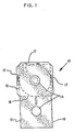
- Fig. 1 is a schematic diagram showing a prepunched flexible material blank from which the envelope is formed.
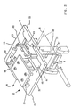
- Fig. 2 is a perspective diagram showing the centerfold apparatus and the attached side flap folding and bonding apparatus.
- Fig. 3 is a perspective diagram showing the side flap folding mechanism.
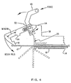
- Fig. 4 is a schematic diagram illustrating the side flap folding apparatus before the flap folding operation.
- Fig. 5 is a schematic diagram showing the side flap folding apparatus before the compression movement.
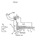
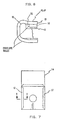
- Fig. 6 is a schematic diagram showing the side flap folding apparatus after the compression force is applied.
- Fig. 7 is a schematic diagram showing the mandrel with the plastic blank formed thereabout.
- Fig. 8 is a cross-sectional view along the line 8-8 of Fig. 5 showing the side flap folded over the raised portion of the mandrel.
- Fig. 9 is an illustrative diagram showing the heating means on three sides of the open envelope.
- Fig. 10 is a schematic diagram along the line 10-10 showing the reflector shape and location of the bulb thereon.
- the plastic blank 10, shown in Fig. 1 is precut from a flexible plastic material and has a liner material 12 applied to one side which performs an anti-static and cleaning function on the magnetic disk in the finished envelope.
- the blank is prepunched to have a drive hole 14 in each of two equal sections 15 and 16 except that the section 15 has flaps 17 extending from the end and two sides thereof.
- the drive holes 14 are located in the same relative position in the sections 15 and 16 and are aligned during bending of the sections so that the centerfold 18 can be located and formed in the middle of the two sections 15 and 16.
- the centerfold apparatus of the machine consists of two flat folding plates 21 and 23, shown in Fig. 2. Each of these plates has a different mechanism attached to the rear surface thereof.
- Plate 23 has the side flap folding mechanism 20 of this invention attached to the back surface thereof and the plate 21 is designed to have the thermal spot bonding mechanism 22 attached to the back surface thereof.
- the folding plates 21 and 23 pivot about axis 28 and are actuated by a linkage which is driven by a cam (not shown). These plates 21 and 23, when actuated, move either up or down along an arcuate path about the pivot axis 28. When actuated upward, the lowermost surfaces 32 and 33 of the plates, form a flat horizontal plane.
- these surfaces 32 and 33 When actuated downward, these surfaces 32 and 33 rotate 90° to the vertical plane, and are machined such that when in the vertical position, a gap of .050 inches (1.27 mm) exists between these surfaces. This space is provided for by a .030 inch (0.76 mm) thick steel folding mandrel 34, over which the product is formed, and two product thicknesses i.e. one thickness on either side of the mandrel.
- the transfer shuttle carriage moves forward transferring a flat flexible plastic blank 10 to the underside of the folding plates 21 and 23.
- the flat plastic blank 10 is held against the horizontal plate surfaces 32 and 33 by vacuum, and is accurately located by hubs which protrude below the plate surfaces.
- the blank When the centerfold is completed, and the folding plates 21 and 23 are in the vertical position, the blank is folded in half and locked in place by the folding plates 21 and 23 which apply pressure against the product surfaces and the steel mandrel 34. It should be appreciated that the side flaps 17 extend beyond the folding mandrel 34 and that the folding plates 21 and 23 have cut out portions 41 and 42 along the side edges thereof so that the underlying section of the flexible blank is exposed.
- the side flap folding operation is now initiated.
- the side flap folding mechanism 20 is attached to the back of folding plate 23.
- the flexible blank 10 is brought in or positioned on the input shuttle (not shown) such that the section 15 of the blank with the side flaps 17 extending therefrom is first.
- the side flap folding mechanism 20 contains two folding blades 44 and 46. Blade 44 folds the flap 17 about one side edge of the product and mandrel 34 and the other blade 46 folds the side flap 17 around the other side edge of the product and mandrel 34.
- the pivoting mechanism 50 for the folding blade 44 can best be seen in Fig. 3 in which there is a stationary pin 52 and a rotating pin 54.
- the blade 46 and its pivoting mechanism are a mirror image of the blade 44 and its pivoting mechanism as indicated in Fig. 2.
- the stationary pin 52 is fixed in the framework 58 and serves as the pivot about which the pivoting or operating force is obtained by a force applied to the lever 60.
- the force is applied by controlled air cylinder 59 as indicated in Fig. 2.
- the applied force causes rotation about the stationary pivot pin 52 so that the end of the L-shaped member or folding blade 44 intercepts the envelope flap 17 and begins the fold as shown in Fig. 4.
- the various positions of the envelope flap 17 as the folding blade continues to move as a result of the pivoting about fixed pivot pin 52 are shown by dashed lines.
- the resulting position of the folding blade 44 is shown in Fig. 5 wherein the stop 64 is against the frame 58 or plate 23.
- the stationary pin 52 about which the folding blade 44 rotates passes through a slot 66 in the top of the folding blade 44.
- the stationary pin 52 is spring loaded by spring 68 upward in the slot 66.
- the folding blade 44 rotates until the stop 64 is against the plate 23 having cleared the mandrel 34 and opposite section 16 of the blank 10, providing an "ironing" action on the flap 17.
- the rotating pin 54 continues to travel upward about the stationary pivot pin 52, pulling the folding blade upward against the spring 68 force, as illustrated in Fig. 6.
- This allows the stop 64 to slide vertically against the plate 23 until the designed compression of the folding blade against the flap is achieved.
- one force action causes the folding blade 44 to perform the necessary folding and compression force against the flap 17.
- the resulting fold is supported by the mandrel 34 which has a raised portion 70 along both vertical sides at the outermost edges as shown in Figs. 6, 7 and 8.
- the raised portion 70 is raised a distance of approximately .018 inches (0.46 mm) above the flat face of the mandrel 34. It should be noted that the raised portions 70 are on the surface of the mandrel 34 facing away from the folding mechanism. These raised portions 70 of the surface extend in width from the side edges of the mandrel inward towards the mandrel center line for a distance of about .020 inches (0.51 mm), on each edge. The raised portions 70 are radiused on all edges so that a smooth surface transition takes place during folding and assures that there are no sharp edges which might cut or mark the product.
- a pocket 72 (Fig. 8) forms on the inside of the raised portion 70 into which the flap 17 and product section fit.
- the overbend should be sufficient in that the so-called material memory will bring the flap 17 back to the desired normal position during the thermal setting process of the folded product edges which follows the overbending operation.
- the raised portions 70 of the mandrel 34 along the side edges thereof provide a bend of sufficient radius that the desired clearance between the inserted floppy disk and the envelope is obtained.
- the use of the mandrel 34 of a predetermined thickness establishes the distance between the inner faces of the envelope such that a particular clearance opening is provided so that a predetermined amount of friction to torque is obtained by the wiping material against the surfaces of the disk.
- the folding blade 44 has a window or cutout slot 74 therein that runs along the fold in the product such that thermal energy can be applied through the window to the fold.
- the window 74 has sloped top and bottom surfaces 76 and 78 such that the heat is directed to the fold and is blocked from impinging on the other parts of the apparatus.
- the heat energy is supplied by three infrared heat lamps 80, see Figs. 9 and 10, one extending along each of the edges of the mandrel 34 about which a fold has been formed.
- a heat lamp 80 extending along the side edges and bottom edge of the formed product 78.
- the controller (not shown) which controls these lamps is so designed that each lamp is independently controlled. The power to each lamp may be increased or decreased as required, as may the time the individual lamps are turned on. This allows the operator to compensate for product or process variations.
- the infrared lamps 80 include elliptical reflectors 82 so that nearly all of the radiant energy generated by the long infrared bulbs 84 would be focused at the adjacent folded edge of the product, as shown in Fig. 10. This focused energy causes a very quick temperature rise in the folded product edges.
- a small jet of compressed air is directed over the heated surface to aid in lowering the fold temperature to ambient.
- the folding blades or bars 44 retract, leaving the folded side flaps 17 in place, ready to be spot bonded.
- the mandrel 34 is stripped from the blank and a disk is inserted.
- the third or end flap fold and bond takes place to complete the diskette.
Landscapes
- Making Paper Articles (AREA)
Description
- The invention relates to apparatus for manufacturing the envelope for a flexible (floppy) disk and, more particularly, to the side flap fold forming apparatus for a prepunched blank which forms the side edges of an envelope for a flexible disk.
- Flexible disks, known as floppy disks, are generally made of plastic and are utilized for recording and reading information usually in an off-line mode in a data processing system. These flexible disks are light weight, relatively low cost and convenient to use. The disks are packaged in envelopes formed from sheets of flexible plastic such as polyvinyl chloride. The envelopes have aligned center or drive holes which allow the enclosed flexible disk to be rotated within the envelope. The envelope is lined with layers of a low friction liner material. The envelope includes slots which permit writing and reading into and from the disk.
- The flexible plastic envelopes are formed from precut and prepunched sheets of plastic material which has the center drive holes and access slots prepunched therein. Half of a precut sheet or blank is rectangular and the other half is identical, except that it includes three flaps which extend from its three outer edges. The low friction liner or wiping material is attached to the inner surface of the sheet prior to cutting and punching. The envelope is formed by making a centerfold therein by folding each half of the sheet against the other half. The side flaps are folded around the edges of the opposite half of the sheet and are sealed thereto. A flexible disk is then inserted into the envelope and the third or end flap is then folded to complete assembly of the flexible disk and envelope. The centerfold and the side flap folds must be exactly located and formed in order to meet the specifications for the flexible disk unit. If the folds are of too small a radius, the friction between the disk and the liner will increase the torque required by the flexible disk drive system. Too large a fold radius will result in insufficient friction of wiping material against the disk resulting in an out-of-specification flexible disk unit. Warpage of the completed flexible disk unit must be kept within tight tolerances to produce an acceptable flexible disk system.
- It is known from the prior art that folding bars are used to bend flaps over mandrels or bending plates to form the side edges of a prepunched flexible blank. The folding bars are usually moved in an arcuate path contacting the flap to be folded and folding it over a folding plate. In most instances, the folding bar holds the folded over flap in position while heat is applied usually through the heating bar to thermal set the fold. US-A-4,272,235, issued June 9, 1981, shows such an apparatus as just briefly described for making a fold in the side edges of the blank. The fold bar in the patent moves along an arcuate path controlled by a four bar linkage, folding the flap back against the adjacent section of the blank and simultaneously forcing the fold end of the flap against a resilient pad adjacent a rigid stop attached to the support surface, producing a permanent end fold having controlled radius of curvature.
- The forming of the side folds around the mandrel and then heating the fold to cause annealing of the plastic material and then bonding or sealing the flap to the underlying plastic surface has resulted in a large number of rejections of the final diskettes because of the tendency of the material that is folded to have a memory which causes it to unbend slightly thereby causing the underlying surface to which it is bonded to also rise thereby giving a bulge in the envelope.
- The Invention as claimed is intended to remedy the drawbacks of the prior art.
- Accordingly, it is the main feature of the present invention to overstress the side flap fold bend so that the memory will bring it back to the plane which is desired and eliminate the undesired bulge.
- It is a further feature of the present invention to provide a radiused edge portion on the mandrel about which the fold is made.
- It is another feature of the present invention to provide a folding apparaus which forms the fold and also provides overstressing of the material at the fold to compensate for material memory return.
- As can be seen, the prior art does not use a mandrel having a raised edge section over which the flexible material is folded by the bar, nor does it have the apparatus for overstressing the fold just beyond the raised portion of the mandrel edge so as to produce an overstressed section which, after heating and cooling, raises slightly due to material memory into the desired plane.
- Fig. 1 is a schematic diagram showing a prepunched flexible material blank from which the envelope is formed.
- Fig. 2 is a perspective diagram showing the centerfold apparatus and the attached side flap folding and bonding apparatus.
- Fig. 3 is a perspective diagram showing the side flap folding mechanism.
- Fig. 4 is a schematic diagram illustrating the side flap folding apparatus before the flap folding operation.
- Fig. 5 is a schematic diagram showing the side flap folding apparatus before the compression movement.
- Fig. 6 is a schematic diagram showing the side flap folding apparatus after the compression force is applied.
- Fig. 7 is a schematic diagram showing the mandrel with the plastic blank formed thereabout.
- Fig. 8 is a cross-sectional view along the line 8-8 of Fig. 5 showing the side flap folded over the raised portion of the mandrel.
- Fig. 9 is an illustrative diagram showing the heating means on three sides of the open envelope.
- Fig. 10 is a schematic diagram along the line 10-10 showing the reflector shape and location of the bulb thereon.
- The plastic blank 10, shown in Fig. 1, is precut from a flexible plastic material and has a
liner material 12 applied to one side which performs an anti-static and cleaning function on the magnetic disk in the finished envelope. The blank is prepunched to have adrive hole 14 in each of twoequal sections section 15 hasflaps 17 extending from the end and two sides thereof. Thedrive holes 14 are located in the same relative position in thesections centerfold 18 can be located and formed in the middle of the twosections - The centerfold apparatus of the machine consists of two
flat folding plates Plate 23 has the sideflap folding mechanism 20 of this invention attached to the back surface thereof and theplate 21 is designed to have the thermalspot bonding mechanism 22 attached to the back surface thereof. Thefolding plates axis 28 and are actuated by a linkage which is driven by a cam (not shown). Theseplates pivot axis 28. When actuated upward, thelowermost surfaces surfaces steel folding mandrel 34, over which the product is formed, and two product thicknesses i.e. one thickness on either side of the mandrel. - When the plates are actuated to the upward position, the transfer shuttle carriage (not shown), moves forward transferring a flat flexible plastic blank 10 to the underside of the
folding plates horizontal plate surfaces - After a flat flexible plastic blank 10 has been placed on the folding plate and is held in position by the plate vacuum, a folding
mandrel 34 is actuated upward to apply pressure against the lower face of the product blank in the fold centerline area. When thefolding plates mandrel 34. The centerfold forming apparatus is described in more detail in co-pending US patent application S.N. 698513 filed on February 4, 1985. - When the centerfold is completed, and the
folding plates folding plates steel mandrel 34. It should be appreciated that theside flaps 17 extend beyond thefolding mandrel 34 and that thefolding plates portions flap folding mechanism 20 is attached to the back offolding plate 23. The flexible blank 10 is brought in or positioned on the input shuttle (not shown) such that thesection 15 of the blank with theside flaps 17 extending therefrom is first. The sideflap folding mechanism 20 contains twofolding blades Blade 44 folds theflap 17 about one side edge of the product andmandrel 34 and theother blade 46 folds the side flap 17 around the other side edge of the product andmandrel 34. - The
folding blades flaps 17 and are positioned away from thefolding plate 23 center line so as to clear thevertical edges mandrel 34. Thepivoting mechanism 50 for thefolding blade 44 can best be seen in Fig. 3 in which there is astationary pin 52 and a rotatingpin 54. Theblade 46 and its pivoting mechanism are a mirror image of theblade 44 and its pivoting mechanism as indicated in Fig. 2. Thestationary pin 52 is fixed in theframework 58 and serves as the pivot about which the pivoting or operating force is obtained by a force applied to thelever 60. The force is applied by controlledair cylinder 59 as indicated in Fig. 2. The applied force causes rotation about thestationary pivot pin 52 so that the end of the L-shaped member orfolding blade 44 intercepts theenvelope flap 17 and begins the fold as shown in Fig. 4. The various positions of theenvelope flap 17 as the folding blade continues to move as a result of the pivoting about fixedpivot pin 52 are shown by dashed lines. The resulting position of thefolding blade 44 is shown in Fig. 5 wherein thestop 64 is against theframe 58 orplate 23. Thestationary pin 52 about which thefolding blade 44 rotates passes through aslot 66 in the top of thefolding blade 44. Thestationary pin 52 is spring loaded byspring 68 upward in theslot 66. Thefolding blade 44 rotates until thestop 64 is against theplate 23 having cleared themandrel 34 andopposite section 16 of the blank 10, providing an "ironing" action on theflap 17. As further force is applied to thelever 60, the rotatingpin 54 continues to travel upward about thestationary pivot pin 52, pulling the folding blade upward against thespring 68 force, as illustrated in Fig. 6. This allows thestop 64 to slide vertically against theplate 23 until the designed compression of the folding blade against the flap is achieved. It should be appreciated that one force action causes thefolding blade 44 to perform the necessary folding and compression force against theflap 17. The resulting fold is supported by themandrel 34 which has a raisedportion 70 along both vertical sides at the outermost edges as shown in Figs. 6, 7 and 8. The raisedportion 70 is raised a distance of approximately .018 inches (0.46 mm) above the flat face of themandrel 34. It should be noted that the raisedportions 70 are on the surface of themandrel 34 facing away from the folding mechanism. These raisedportions 70 of the surface extend in width from the side edges of the mandrel inward towards the mandrel center line for a distance of about .020 inches (0.51 mm), on each edge. The raisedportions 70 are radiused on all edges so that a smooth surface transition takes place during folding and assures that there are no sharp edges which might cut or mark the product. A pocket 72 (Fig. 8) forms on the inside of the raisedportion 70 into which theflap 17 and product section fit. When the side flaps 17 are folded, a line-to-line condition exists between the outside flat face of theproduct section 16 and the inside surface of the foldedflap 17. The added compression provided by thefolding plate 44 produces a slight "overbend" which compensates for rebound of the plastic material after it is thermal set. The plastic material appears to have a memory which, after thermal setting, has the effect of returning a slight bit towards its former position. If the side flaps 17 are not overbent, as is shown in Figs. 7 and 8, the side flaps attempt to spring open slightly when the folding blade pressure is removed, causing a small gap to occur between theflap edge 17 and the flat face of theproduct section 16. This condition interferes with a good thermal spot bond of theflap 17 to theproduct section 16 and is also somewhat unsightly if a thermal bond does occur. The overbend should be sufficient in that the so-called material memory will bring theflap 17 back to the desired normal position during the thermal setting process of the folded product edges which follows the overbending operation. - The raised
portions 70 of themandrel 34 along the side edges thereof provide a bend of sufficient radius that the desired clearance between the inserted floppy disk and the envelope is obtained. The use of themandrel 34 of a predetermined thickness establishes the distance between the inner faces of the envelope such that a particular clearance opening is provided so that a predetermined amount of friction to torque is obtained by the wiping material against the surfaces of the disk. - The
folding blade 44 has a window orcutout slot 74 therein that runs along the fold in the product such that thermal energy can be applied through the window to the fold. Thewindow 74 has sloped top andbottom surfaces - The heat energy is supplied by three
infrared heat lamps 80, see Figs. 9 and 10, one extending along each of the edges of themandrel 34 about which a fold has been formed. Thus, there is aheat lamp 80 extending along the side edges and bottom edge of the formedproduct 78. The controller (not shown) which controls these lamps is so designed that each lamp is independently controlled. The power to each lamp may be increased or decreased as required, as may the time the individual lamps are turned on. This allows the operator to compensate for product or process variations. Theinfrared lamps 80 includeelliptical reflectors 82 so that nearly all of the radiant energy generated by the longinfrared bulbs 84 would be focused at the adjacent folded edge of the product, as shown in Fig. 10. This focused energy causes a very quick temperature rise in the folded product edges. - After the completion of the heat set cycle, a small jet of compressed air is directed over the heated surface to aid in lowering the fold temperature to ambient.
- Following the side flap folding and thermal setting operations, the folding blades or bars 44 retract, leaving the folded side flaps 17 in place, ready to be spot bonded.
- After the spot bonding operation, the
mandrel 34 is stripped from the blank and a disk is inserted. The third or end flap fold and bond takes place to complete the diskette.
Claims (16)
- Apparatus for forming side flap folds in an envelope for a flexible disk from a flexible plastic prepunched blank (10) with two connected sections (15, 16) and side flaps (17) extending from opposite side edges of one section (15) of said blank (10), comprising a folding flat plate (21, 23), a pair of folding blades (44, 46), a pair of pivot means (52) located within the apparatus frame to guide the associated folding blades (44, 46) in an arcuate path to fold the associated flap (17), drive means (59, 60) for rotating said folding blades (44, 46) about said pivot means (52), stop means (64) for stopping said folding blades arcuate path movement, characterised in that said folding plate (21, 23) comprises two hinged sections which pivot about an axis (28) and said apparatus further comprises a mandrel (34) having the flexible plastic blank (10) folded about an end thereof so that said side flaps (17) of the blank (10) extend beyond the side edges of said mandrel (34), said mandrel (34) holding the plastic blank section (15) with the flaps (17) against the bottom surface of said plate (23), a raised edge portion (70) extending along the side edges of said mandrel (34), on the bottom surface thereof against the bottom blades (44, 46) being rotated about the corresponding pivot means (52), associated with each of the two side flaps (17), in opposite directions around the adjacent edge of said mandrel (34), and upward motion means (54, 68) associated with each of said pivot means (52) and operable subsequent to said pivot means and said stop means operation in response to said drive means (59, 60) to cause compression of said flaps (17) by said folding blades (64 beyond said raised edge portions (70), in order to provide an overbent zone adjacent to said raised edge portions.
- The apparatus of claim 1, further including radiant heating means (80,84) operable to anneal each of said folds relieving any stresses therein.
- An apparatus according to claim 2, wherein each of said radiant heating means includes an infra-red heating bulb (80), of a length equal to the length of said associated aside flap fold.
- An apparatus according to claim 3, wherein each of said infra-red heating bulbs (80) is located in a reflector (84) having a length at least as long as said infra-red heating bulb (80) and curved so as to provide a line of focus points lying along the length of the fold to be annealed.
- An apparatus according to any claim 2 through 4 further including guiding means (74,76,78) for directing said radiant heat to said folds and shielding non-folded areas from the heat.
- An apparatus according to claim 5, wherein said guiding means (74,76,78) includes a window (74) extending through each of said folding blades (44,46) adjacent said folds and having inwardly slanting sides (76,78) such that radiant heat from the radiant heating means (80,84) is directed towards the adjacent flap fold (17) and away from other parts of the apparatus.
- An apparatus according to any preceding claim, wherein each of said folding blades (44,46) is L-shape in cross-section and has a width substantially equal to the length of said flaps (17) along their respective edge of the blank (10).
- An apparatus according to claim 7 wherein each of said pivot means (52) includes a fixed pivot pin (52) extending along the width of said folding blades (44).
- An apparatus according to claim 8, wherein each of said upward motion means includes an elongated vertical groove at the top of each of said folding blades having the central axis thereof extending along the width of said folding blades, a fixed pivot pin (52) passing through a respective one of said elongated grooves extending parallel to the central axis thereof, a spring means (68) compressed between the bottom of each of said elongated grooves and said respective fixed pivot pin (52) biasing said fixed pivot pins into the top part of said respective elongated groove, and a pair of rotating pivot pins (54) each located a predetermined distance in front of said associated elongated groove and extending parallel to the central axis of said elongated groove.
- An apparatus according to any of claims 7 to 9, wherein said drive means (59,60) for rotating said folding blades (44,46) about said pair of pivot means (52) consists of pneumatic drive means (59) for rotating said L-shaped folding blades (44) so that the lower ends thereof move in an arcuate path and intercept the laterally extending flaps (17) of said blank (10) causing them to fold outward about the adjacent side edges of said mandrel (34).
- An apparatus according to claim 9 or 10, wherein the upward motion of said respective folding blade (44,46) is caused by the further force applied by said drive means (59,60) to said folding blade (44,46) about said fixed pivot means (52) after said stop means engagement causing said rotating pivot pin (54) to rise lifting said folding blade (44,46) upward which causes said spring means (68) to be compressed against said fixed pivot pins (52) providing compression of each of said flaps (17) beyond said raised edge portion (70) providing an overbent zone adjacent thereto.
- An apparatus according to any of claims 9 to 11, wherein the distance between said fixed pin (52) and said rotating pin (54) and said stationary pin (52) and said drive means force application point is directly proportional to the resultant compression applied by said folding blades (44,46) to said flaps (17) to cause the overbent zone adjacent said raised edge portions (70).
- An apparatus according to any of claims 9 to 12, wherein a spring hole is located at the bottom of each elongated vertical groove for containing said spring means (68), a plunger held by said spring means and pressing against said respective fixed pivot pin (52).
- An apparatus according to any of claims 7 to 13, wherein said folding blades (44,46) each have an upward facing raised surface portion at the end of the short arm of the L-shaped folding blade (44,46), the non-raised portion serving as an open area into which the flap portion surrounding the raised edge portion (70) can extend during the compression of said flap (17) beyond said raised edge portion (70).
- An apparatus according to any preceding claim, wherein said stop means (64) are located on each of said folding blades (44,46) and operates against said plate (23) to interrupt the movement of said associated folding blade (44,46) in an arcuate path.
- An apparatus according to any preceding claim, wherein said raised edge portion (70) along the side edges of said mandrel (34) have a predetermined height, width and a curved surface thereon defining the shape of the fold of the plastic material folded thereabout by said folding blade (44,46).
Applications Claiming Priority (2)
| Application Number | Priority Date | Filing Date | Title |
|---|---|---|---|
| US698212 | 1985-02-04 | ||
| US06/698,212 US4617081A (en) | 1985-02-04 | 1985-02-04 | Side flap fold apparatus for a disk envelope |
Publications (3)
| Publication Number | Publication Date |
|---|---|
| EP0190580A2 EP0190580A2 (en) | 1986-08-13 |
| EP0190580A3 EP0190580A3 (en) | 1988-08-03 |
| EP0190580B1 true EP0190580B1 (en) | 1991-05-29 |
Family
ID=24804343
Family Applications (1)
| Application Number | Title | Priority Date | Filing Date |
|---|---|---|---|
| EP86100562A Expired - Lifetime EP0190580B1 (en) | 1985-02-04 | 1986-01-17 | Flap folding apparatus for a disk envelope |
Country Status (4)
| Country | Link |
|---|---|
| US (1) | US4617081A (en) |
| EP (1) | EP0190580B1 (en) |
| JP (1) | JPS61177694A (en) |
| DE (1) | DE3679414D1 (en) |
Families Citing this family (21)
| Publication number | Priority date | Publication date | Assignee | Title |
|---|---|---|---|---|
| JPS61184775A (en) * | 1985-02-13 | 1986-08-18 | Mitsubishi Plastics Ind Ltd | Production of floppy disk jacket |
| JPS61280084A (en) * | 1985-06-05 | 1986-12-10 | Shin Etsu Polymer Co Ltd | Folding method for sealing flap of disc jacket |
| DE3521383A1 (en) * | 1985-06-14 | 1986-12-18 | Basf Ag, 6700 Ludwigshafen | METHOD AND DEVICE FOR PRODUCING SLEEVES FOR FLEXIBLE MAGNETIC DISC DISKS |
| SE465214B (en) * | 1990-01-16 | 1991-08-12 | Tetra Pak Holdings Sa | SETTLE TO HEAT PART OF CURRENT MATERIALS |
| US5324384A (en) * | 1992-12-23 | 1994-06-28 | R & S Stanztechnik Gmbh | Apparatus for laminating a trim panel and folding a brim around the panel rim |
| US5342370A (en) * | 1993-03-19 | 1994-08-30 | University Of Miami | Method and apparatus for implanting an artifical meshwork in glaucoma surgery |
| DE4400388C2 (en) * | 1994-01-08 | 1998-08-27 | Roeder & Spengler Stanz | Method and device for producing a molded part from at least one carrier layer and a lamination layer |
| ES2110330B1 (en) * | 1994-01-21 | 1998-09-01 | Embalaje Iberoamericana | PROCEDURE AND DEVICE TO FORM SUPPORTS IN STACKABLE CONTAINERS AND CONTAINERS SO OBTAINED. |
| US5439436A (en) * | 1994-05-18 | 1995-08-08 | Moll; Richard J. | Boxed pocket folding machine |
| US5718791A (en) * | 1995-06-05 | 1998-02-17 | R + S Stanztechnik Gmbh | Method of laminating a trim panel and folding a cover sheet edge around the panel rim |
| US5732818A (en) * | 1996-03-20 | 1998-03-31 | R.R. Donnelley & Sons Company | Compact disc package |
| US5852915A (en) * | 1996-09-26 | 1998-12-29 | R. R. Donnelley & Sons Company | Method of making compact disc product |
| DE19924395B4 (en) * | 1999-05-27 | 2009-03-19 | Bayerische Motoren Werke Aktiengesellschaft | Device for attaching a flexible cover on the edge region of a support member |
| US7726099B2 (en) * | 2006-10-24 | 2010-06-01 | Better Case Sealer Llc | Semi-automatic (human powered) case sealing machine |
| DE102008006715A1 (en) * | 2008-01-30 | 2009-08-06 | Faurecia Innenraum Systeme Gmbh | Method for laminating a multilayer plastic component |
| JP5267174B2 (en) * | 2009-02-03 | 2013-08-21 | ソニー株式会社 | Stereolithography apparatus and modeling base |
| CA2830279C (en) | 2012-10-19 | 2020-10-20 | Rock-Tenn Shared Services, Llc | Container forming apparatus and method |
| US11433634B2 (en) * | 2012-10-19 | 2022-09-06 | Westrock Shared Services, Llc | Container forming apparatus and method |
| US9573336B2 (en) * | 2013-08-07 | 2017-02-21 | Plymouth Packaging Inc. | Apparatus for automatically gluing head and tail ends of stock material |
| US9409371B1 (en) | 2014-03-14 | 2016-08-09 | Chicago Tag & Label, Inc. | Label folding apparatus and methods for its use |
| US9302444B1 (en) * | 2014-03-14 | 2016-04-05 | Chicago Tag & Label, Inc. | Label folding apparatus and methods for its use |
Family Cites Families (9)
| Publication number | Priority date | Publication date | Assignee | Title |
|---|---|---|---|---|
| DE2842185A1 (en) * | 1978-09-28 | 1980-04-10 | Basf Ag | METHOD FOR THE PRODUCTION OF PROTECTIVE COVERS FOR FLEXIBLE DATA CARRIERS |
| US4272235A (en) * | 1978-11-24 | 1981-06-09 | Three Phoenix Company | Method and apparatus for folding and sealing a floppy disc envelope |
| DE8012859U1 (en) * | 1980-05-12 | 1980-09-25 | Basf Ag | Device for the production of protective sleeves for disk-shaped data carriers |
| US4367117A (en) * | 1981-03-16 | 1983-01-04 | Discover Technology, Inc. | Machine for sealing disc covers |
| US4530729A (en) * | 1981-06-05 | 1985-07-23 | Evana Tool & Engineering Inc. | Folding of flat sheet to exact interior height |
| US4415325A (en) * | 1981-06-05 | 1983-11-15 | Evana Tool & Engineering Inc. | Folding of flat sheet to exact interior height |
| US4470795A (en) * | 1982-11-23 | 1984-09-11 | Rca Corporation | Apparatus for manufacturing a disc record package |
| US4475966A (en) * | 1983-07-25 | 1984-10-09 | Rca Corporation | Method and apparatus for manufacturing video disc caddy |
| JPH0628926B2 (en) * | 1984-02-28 | 1994-04-20 | 信越ポリマー株式会社 | Bag-shaped case manufacturing equipment |
-
1985
- 1985-02-04 US US06/698,212 patent/US4617081A/en not_active Expired - Fee Related
- 1985-11-13 JP JP60253006A patent/JPS61177694A/en active Granted
-
1986
- 1986-01-17 EP EP86100562A patent/EP0190580B1/en not_active Expired - Lifetime
- 1986-01-17 DE DE8686100562T patent/DE3679414D1/en not_active Expired - Fee Related
Also Published As
| Publication number | Publication date |
|---|---|
| US4617081A (en) | 1986-10-14 |
| JPS61177694A (en) | 1986-08-09 |
| JPH0413793B2 (en) | 1992-03-10 |
| EP0190580A3 (en) | 1988-08-03 |
| DE3679414D1 (en) | 1991-07-04 |
| EP0190580A2 (en) | 1986-08-13 |
Similar Documents
| Publication | Publication Date | Title |
|---|---|---|
| EP0190580B1 (en) | Flap folding apparatus for a disk envelope | |
| EP0305092B1 (en) | Expandable collapsible product and method and apparatus for its manufacture | |
| US7478988B2 (en) | Apparatus and method for manufacturing hard book cover assemblies | |
| US4367061A (en) | Method and apparatus for producing book covers, folders, booklets and the like | |
| US4272235A (en) | Method and apparatus for folding and sealing a floppy disc envelope | |
| JP6698249B2 (en) | Computer-controlled method for bending profiles to make a frame for insulating glass having either double or triple glass frames and equipment for carrying out the method | |
| EP1380547B2 (en) | Glass plate bend-forming method and device | |
| EP0190579B1 (en) | Centerfold forming apparatus for a disk envelope | |
| JPH07285521A (en) | Method and device for sticking adhesive tape | |
| EP0649734A2 (en) | Packaging | |
| CA1073340A (en) | Manufacture of a window by breaking the edges of a sheet of glass along a score | |
| EP0599650A1 (en) | Method and apparatus for folding bottom panels of a carton blank | |
| US4367117A (en) | Machine for sealing disc covers | |
| US4854033A (en) | Inserting insulating material into electric motor stators | |
| GB2161427A (en) | Forming containers | |
| KR900006638B1 (en) | The manufacturing device of disk case | |
| EP1944274A1 (en) | Method and Machine for cutting laminated glass | |
| US5282912A (en) | Method for applying bead flipper | |
| US3786529A (en) | Bookbinding machine with endleaf folding means | |
| US5047000A (en) | Attachment for forming envelopes | |
| US2318849A (en) | Method of making toy structural elements | |
| US3187647A (en) | Rotating carton tucker apparatus | |
| US2726498A (en) | Mechanism for folding carton flaps | |
| JPS608769B2 (en) | A device that aligns the fish in the necessary position for cutting the fish's neck. | |
| JPH048533Y2 (en) |
Legal Events
| Date | Code | Title | Description |
|---|---|---|---|
| PUAI | Public reference made under article 153(3) epc to a published international application that has entered the european phase |
Free format text: ORIGINAL CODE: 0009012 |
|
| AK | Designated contracting states |
Kind code of ref document: A2 Designated state(s): DE FR GB |
|
| 17P | Request for examination filed |
Effective date: 19861212 |
|
| PUAL | Search report despatched |
Free format text: ORIGINAL CODE: 0009013 |
|
| AK | Designated contracting states |
Kind code of ref document: A3 Designated state(s): DE FR GB |
|
| RHK1 | Main classification (correction) |
Ipc: G11B 23/03 |
|
| 17Q | First examination report despatched |
Effective date: 19900108 |
|
| GRAA | (expected) grant |
Free format text: ORIGINAL CODE: 0009210 |
|
| AK | Designated contracting states |
Kind code of ref document: B1 Designated state(s): DE FR GB |
|
| REF | Corresponds to: |
Ref document number: 3679414 Country of ref document: DE Date of ref document: 19910704 |
|
| ET | Fr: translation filed | ||
| PLBE | No opposition filed within time limit |
Free format text: ORIGINAL CODE: 0009261 |
|
| STAA | Information on the status of an ep patent application or granted ep patent |
Free format text: STATUS: NO OPPOSITION FILED WITHIN TIME LIMIT |
|
| 26N | No opposition filed | ||
| PGFP | Annual fee paid to national office [announced via postgrant information from national office to epo] |
Ref country code: GB Payment date: 19921222 Year of fee payment: 8 |
|
| PGFP | Annual fee paid to national office [announced via postgrant information from national office to epo] |
Ref country code: FR Payment date: 19921223 Year of fee payment: 8 |
|
| PGFP | Annual fee paid to national office [announced via postgrant information from national office to epo] |
Ref country code: DE Payment date: 19930127 Year of fee payment: 8 |
|
| PG25 | Lapsed in a contracting state [announced via postgrant information from national office to epo] |
Ref country code: GB Effective date: 19940117 |
|
| GBPC | Gb: european patent ceased through non-payment of renewal fee |
Effective date: 19940117 |
|
| PG25 | Lapsed in a contracting state [announced via postgrant information from national office to epo] |
Ref country code: FR Effective date: 19940930 |
|
| PG25 | Lapsed in a contracting state [announced via postgrant information from national office to epo] |
Ref country code: DE Effective date: 19941001 |
|
| REG | Reference to a national code |
Ref country code: FR Ref legal event code: ST |