EP0190194B1 - Crimping press capable of crimping terminals onto a range of wire sizes - Google Patents
Crimping press capable of crimping terminals onto a range of wire sizes Download PDFInfo
- Publication number
- EP0190194B1 EP0190194B1 EP85903492A EP85903492A EP0190194B1 EP 0190194 B1 EP0190194 B1 EP 0190194B1 EP 85903492 A EP85903492 A EP 85903492A EP 85903492 A EP85903492 A EP 85903492A EP 0190194 B1 EP0190194 B1 EP 0190194B1
- Authority
- EP
- European Patent Office
- Prior art keywords
- crimping
- shaft
- anvil
- die
- bearing
- Prior art date
- Legal status (The legal status is an assumption and is not a legal conclusion. Google has not performed a legal analysis and makes no representation as to the accuracy of the status listed.)
- Expired
Links
Images



Classifications
-
- H—ELECTRICITY
- H01—ELECTRIC ELEMENTS
- H01R—ELECTRICALLY-CONDUCTIVE CONNECTIONS; STRUCTURAL ASSOCIATIONS OF A PLURALITY OF MUTUALLY-INSULATED ELECTRICAL CONNECTING ELEMENTS; COUPLING DEVICES; CURRENT COLLECTORS
- H01R43/00—Apparatus or processes specially adapted for manufacturing, assembling, maintaining, or repairing of line connectors or current collectors or for joining electric conductors
- H01R43/04—Apparatus or processes specially adapted for manufacturing, assembling, maintaining, or repairing of line connectors or current collectors or for joining electric conductors for forming connections by deformation, e.g. crimping tool
- H01R43/048—Crimping apparatus or processes
-
- Y—GENERAL TAGGING OF NEW TECHNOLOGICAL DEVELOPMENTS; GENERAL TAGGING OF CROSS-SECTIONAL TECHNOLOGIES SPANNING OVER SEVERAL SECTIONS OF THE IPC; TECHNICAL SUBJECTS COVERED BY FORMER USPC CROSS-REFERENCE ART COLLECTIONS [XRACs] AND DIGESTS
- Y10—TECHNICAL SUBJECTS COVERED BY FORMER USPC
- Y10T—TECHNICAL SUBJECTS COVERED BY FORMER US CLASSIFICATION
- Y10T74/00—Machine element or mechanism
- Y10T74/18—Mechanical movements
- Y10T74/18056—Rotary to or from reciprocating or oscillating
- Y10T74/18248—Crank and slide
Definitions
- This invention relates to crimping presses for crimping terminals onto wires and particularly to a crimping press which is capable of crimping terminals onto wires which lie within a range of wire sizes without adjustment to the press.
- a conventional crimping press has an anvil for supporting an electrical terminal during crimping and a die which is movable towards and away from the anvil.
- the terminal is placed on the anvil, the end of the wire is inserted into the ferrule or barrel of the terminal, and the die is caused to move towards the anvil to the limit of the stroke of the press. The die then returns to its starting position.
- the "crimp height" of the terminal is closely controlled; the crimp height is a measure of the height or maximum vertical dimension of the terminal after crimping and ordinarily, if a terminal is not crimped to the correct crimp height for the terminal and wire combination, an unsatisfactory crimped connection will result.
- the present invention is directed to the achievement of a crimping press which has the capability of crimping terminals onto wires which lie within a predetermined range of wire sizes without making any adjustments to the press.
- a crimping press which has the capability of crimping terminals onto wires which lie within a predetermined range of wire sizes without making any adjustments to the press.
- the invention comprises a crimping apparatus or press of the type comprising an anvil for supporting the terminal, a crimping die which is movable along a path of reciprocation towards and away from the anvil between the remote position and a closed or shut height position.
- the crimping die is moved by a rotatable power shaft which has an axis that extends normally of the path of reciprocation of the die and the shaft is coupled to the crimping die by a mechanical coupling such that the crimping die is moved to and fro during each revolution of the shaft.
- the apparatus is particularly characterized in that the power shaft is movable in a direction perpendicular to its axis along the path of reciprocation and away from the crimping anvil.
- the power shaft is supported against such movement by a resiliently yieldable shaft support.
- the yieldable shaft support is calibrated to resiliently yield upon development of a predetermined reaction force during the final stages of a crimping operation, the predetermined reaction force is that force which is sufficient to crimp terminals onto wires which lie within a predetermined range of wire sizes.
- the mechanical coupling between the power shaft and the crimping die is an eccentric type coupling comprising an eccentric crank type coupling.
- the shaft is supported in a first shaft bearing which is located adjacent to the mechanical coupling and a biasing means is provided which bears against the first shaft bearing and biases the bearing and the shaft towards the anvil. The first bearing is movable with the power shaft away from the anvil.
- the first bearing is a two-part bearing having a movable portion and a fixed portion, the biasing means being in engagement with the movable portion and serving to maintain the movable portion against the fixed portion of the bearing.
- the biasing means comprises a piston rod of a pneumatic piston-cylinder and the biasing force is thereby determined by the dimensions of the piston and the pressure of the air in the piston-cylinder.
- the crimping press of the invention serves to crimp a terminal 4 onto the end 8 of a wire 2.
- the terminal has a ferrule portion 6 in which the wire is received and which is compressed onto the wire as shown in Figure 1B.
- the apparatus generally comprises an anvil 10 for supporting the terminal, a crimping die 12 which is coupled by a link 13 to a block 14 mounted on a crank pin 16.
- the crank pin is on the end of a power shaft 18 which extends horizontally in Figure 1A and which is supported in first and second bearing assemblies 20, 22.
- the shaft is upwardly movable by a very slight amount from the position shown in Figure 1A but is maintained in the position of Figure 1A by a yieldable shaft support 24 which bears against the bearing assembly 20 and which exerts a predetermined force F against the bearing assembly 20.
- terminal 4 and the terminal 4A are crimped onto their wires 2 and 2A with the same force although the final dimensions of the two terminals are different when they have been fully crimped onto the wires. No adjustments need be made to the apparatus to achieve the conditions of Figures 2A and 2B after the apparatus has been used to crimp smaller wires as shown in Figures 1A and 1B.
- a specific crimping press 26 in accordance with the invention has a base 28 and a frame 30 within which an electric motor is contained which derives a fly wheel contained in a fly wheel housing 32.
- the crimping die and anvil 12, 10 are mounted within a gap 34 and the shaft 18 has an enlarged diameter end portion 36 which is supported in the bearing assembly 20.
- This bearing assembly is a split bearing having a lower portion 38 and an upper portion 40. the two portions being divided along a horizontal axis as viewed in Figure 5.
- the upper portion is slidably supported in guides 42 which in turn are mounted on vertical guide supports 44.
- the biasing force is imposed on the upper portion 40 of the bearing by a rod 46 which bears against a hardened ware plate 48 in the upper portion of the bearing.
- the rod 46 extends through a cover plate 50 of the frame and into a composite cylinder 54 in which it has a reduced diameter rod section 52.
- a plurality of spaced apart pistons 56 are mounted on the reduced diameter rod section 52, each piston comprising two plate-like members between which there is provided a membrane 48 that is captured in the walls of the cylinder 54 as shown.
- the chambers which are above the membranes 58 are pressurized by a source of compressed air and the rod 46 is thereby urged downwardly and against the upper bearing section 40 with a predetermined force that is determined by the pressure of the air and by the dimensions of the pistons. As shown in Figure 5, when this predetermined force is overcome by the reaction force developed during the crimping operation, the rod 46 can yield as the power shaft is moved upwardly.
- bearings provided at 22 are of the type commonly known as pendulum bearings. see Figure 6. These bearings have an outer race 62, an inner race 64, and spherical bearings 68 between the surfaces of the races.
- the surface of the outer race is generally spherical so that the inner races pivot very slightly with respect to the outer race and such pivoting does take place when the shaft 18 is moved upwardly.
- the amount of actual movement of the shaft 18 is extremely limited; if the crimping press is designed to permit movement of about 1mm at the bearing assembly 20, and if the force F is carefully selected, the press will be capable of crimping wires of three different sizes onto terminals. for example. AWG 18, AWG 20, and AWG 22 wires can be accommodated by the crimping press without adjustment.
Landscapes
- Engineering & Computer Science (AREA)
- Manufacturing & Machinery (AREA)
- Manufacturing Of Electrical Connectors (AREA)
Abstract
Description
- This invention relates to crimping presses for crimping terminals onto wires and particularly to a crimping press which is capable of crimping terminals onto wires which lie within a range of wire sizes without adjustment to the press.
- A conventional crimping press has an anvil for supporting an electrical terminal during crimping and a die which is movable towards and away from the anvil. To crimp a terminal onto a wire, the terminal is placed on the anvil, the end of the wire is inserted into the ferrule or barrel of the terminal, and the die is caused to move towards the anvil to the limit of the stroke of the press. The die then returns to its starting position.
- In order to obtain a satisfactory crimped connection, the "crimp height" of the terminal is closely controlled; the crimp height is a measure of the height or maximum vertical dimension of the terminal after crimping and ordinarily, if a terminal is not crimped to the correct crimp height for the terminal and wire combination, an unsatisfactory crimped connection will result.
- In conventional crimping presses, when the wire size is changed. it is necessary to adjust the stroke of the ram of the crimping press so that the correct crimp height will be obtained for each size wire (e.g. US-A-3639966). The requirement of such adjustments to the press is a frequent cause of defective crimps. The operator may neglect to make the necessary adjustment or the operator might improperly adjust the press when a wire size is changed. Since the adjustments from one wire size to the next wire size are very slight and since the appearance of a satisfactory crimp will be very like the appearance of an imperfect crimp, terminals may be crimped by an operator without realizing that improper procedures are being followed.
- The present invention is directed to the achievement of a crimping press which has the capability of crimping terminals onto wires which lie within a predetermined range of wire sizes without making any adjustments to the press. When an operator is operating a press in accordance with the invention and has available only wires which are within the predetermined range, all of the crimped connections the operator makes will be satisfactory and it is not necessary to rely on the operator to make delicate adjustments to the crimping press when the wire size is changed.
- The invention comprises a crimping apparatus or press of the type comprising an anvil for supporting the terminal, a crimping die which is movable along a path of reciprocation towards and away from the anvil between the remote position and a closed or shut height position. The crimping die is moved by a rotatable power shaft which has an axis that extends normally of the path of reciprocation of the die and the shaft is coupled to the crimping die by a mechanical coupling such that the crimping die is moved to and fro during each revolution of the shaft. The apparatus is particularly characterized in that the power shaft is movable in a direction perpendicular to its axis along the path of reciprocation and away from the crimping anvil. The power shaft is supported against such movement by a resiliently yieldable shaft support. The yieldable shaft support is calibrated to resiliently yield upon development of a predetermined reaction force during the final stages of a crimping operation, the predetermined reaction force is that force which is sufficient to crimp terminals onto wires which lie within a predetermined range of wire sizes.
- In accordance with further embodiments, the mechanical coupling between the power shaft and the crimping die is an eccentric type coupling comprising an eccentric crank type coupling. In accordance with a further embodiment, the shaft is supported in a first shaft bearing which is located adjacent to the mechanical coupling and a biasing means is provided which bears against the first shaft bearing and biases the bearing and the shaft towards the anvil. The first bearing is movable with the power shaft away from the anvil.
- In accordance with a further embodiment, the first bearing is a two-part bearing having a movable portion and a fixed portion, the biasing means being in engagement with the movable portion and serving to maintain the movable portion against the fixed portion of the bearing. The biasing means comprises a piston rod of a pneumatic piston-cylinder and the biasing force is thereby determined by the dimensions of the piston and the pressure of the air in the piston-cylinder.
- Figure 1A is a diagrammatic view of an apparatus in accordance with the invention showing the crimping die in its remote position relative to the anvil and showing a relatively small diameter wire positioned in a terminal which is supported on the anvil.
- Figure 1B is a view similar to Figure 1A but showing the positions of the parts when the die has moved to the limit of its stroke towards the anvil and the terminal has been fully crimped onto the wire.
- Figures 2A and 2B are views similar to Figures 1A and 1B but showing a relatively larger diameter wire and terminal being crimped. l
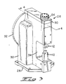
- Figure 3 is a perspective view of a bench crimping press in accordance with the invention.
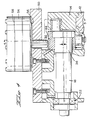
- Figure 4 is a view taken along the lines 4-4 of Figure 3.
- Figure 5 is a view taken along the lines 5-5 of Figure 4 but with the coupling member which couples the crank pin to the die removed.
- Figure 6 is a sectional view of a type of bearing which is used to support the power shaft of the apparatus.
- The principle of the invention will first be described with reference to Figures 1A, 1B, 2A, and 2B and a specific embodiment of the invention will then be described with reference to Figures 3-6.
- Referring first to Figure 1A, the crimping press of the invention serves to crimp a
terminal 4 onto theend 8 of awire 2. The terminal has aferrule portion 6 in which the wire is received and which is compressed onto the wire as shown in Figure 1B. The apparatus generally comprises ananvil 10 for supporting the terminal, acrimping die 12 which is coupled by alink 13 to ablock 14 mounted on acrank pin 16. The crank pin is on the end of apower shaft 18 which extends horizontally in Figure 1A and which is supported in first andsecond bearing assemblies yieldable shaft support 24 which bears against thebearing assembly 20 and which exerts a predetermined force F against thebearing assembly 20. - When a relatively
small diameter wire 2 is to be connected to aterminal 4, the wire is inserted into the ferrule of the terminal and theshaft 18 is rotated through a single revolution to cause downward movement of thedie 12. Since it is assumed that the wire is of a small diameter, at the lower limit of the range of wires which can be accommodated by the apparatus. The die 12 moves to the position of Figure 1B which represents the limit of its travel towards the anvil. Under normal conditions, the reaction force developed.in the terminal in which is exerted on the die is approximately equal to the force F discussed above. - Referring now to Figures 2A and 2B, when a
terminal 4a is to be crimped onto a relativelylarge diameter wire 2a, the parts are positioned as explained before and theshaft 18 is caused to rotate through a single revolution. However. since thewire 2a has a greater diameter than thewire 2, the terminal will be fully crimped and the predetermined reaction force F will be developed prior to the end of the stroke of thedie 12 towards the anvil, that is prior to the time thedie 12 reaches the position of Figure 1 B. Notwithstanding the fact that the die has not reached the position of Figure 1B. the terminal is fully crimped onto the wire when the die reaches the position of Figure 2B. As a result, the reaction force developed in the terminal and wire overcomes the force F and the shaft is pivoted upwardly by a slight amount as shown in Figure 2B so that the downward stroke of the die can be completed. - It will be apparent then that the
terminal 4 and the terminal 4A are crimped onto theirwires 2 and 2A with the same force although the final dimensions of the two terminals are different when they have been fully crimped onto the wires. No adjustments need be made to the apparatus to achieve the conditions of Figures 2A and 2B after the apparatus has been used to crimp smaller wires as shown in Figures 1A and 1B. - It should be mentioned that the movement of
shaft 18 is greatly exaggerated in Figure 2B. The difference in the diameters of thewires terminal 4a is shown as being of a greater diameter than theferrule 6 of theterminal 4. Ordinarily, the only one size of terminal ferrule will be used for the complete range of wire diameters. - Referring now to Figure 3-6, a
specific crimping press 26 in accordance with the invention has abase 28 and aframe 30 within which an electric motor is contained which derives a fly wheel contained in afly wheel housing 32. The crimping die andanvil gap 34 and theshaft 18 has an enlargeddiameter end portion 36 which is supported in thebearing assembly 20. This bearing assembly is a split bearing having alower portion 38 and anupper portion 40. the two portions being divided along a horizontal axis as viewed in Figure 5. The upper portion is slidably supported inguides 42 which in turn are mounted on vertical guide supports 44. - The biasing force is imposed on the
upper portion 40 of the bearing by arod 46 which bears against a hardenedware plate 48 in the upper portion of the bearing. Therod 46 extends through acover plate 50 of the frame and into acomposite cylinder 54 in which it has a reduceddiameter rod section 52. A plurality of spaced apartpistons 56 are mounted on the reduceddiameter rod section 52, each piston comprising two plate-like members between which there is provided amembrane 48 that is captured in the walls of thecylinder 54 as shown. The chambers which are above themembranes 58 are pressurized by a source of compressed air and therod 46 is thereby urged downwardly and against the upper bearingsection 40 with a predetermined force that is determined by the pressure of the air and by the dimensions of the pistons. As shown in Figure 5, when this predetermined force is overcome by the reaction force developed during the crimping operation, therod 46 can yield as the power shaft is moved upwardly. - As shown in Figure 4, there must be some slight movement of the
shaft 18 in the vicinity of thebearing assembly 22 and such pivotal movement can be accommodated if the bearings provided at 22 are of the type commonly known as pendulum bearings. see Figure 6. These bearings have anouter race 62, aninner race 64, andspherical bearings 68 between the surfaces of the races. The surface of the outer race is generally spherical so that the inner races pivot very slightly with respect to the outer race and such pivoting does take place when theshaft 18 is moved upwardly. - It should be mentioned that the amount of actual movement of the
shaft 18 is extremely limited; if the crimping press is designed to permit movement of about 1mm at thebearing assembly 20, and if the force F is carefully selected, the press will be capable of crimping wires of three different sizes onto terminals. for example.AWG 18,AWG 20, andAWG 22 wires can be accommodated by the crimping press without adjustment.
Claims (8)
Applications Claiming Priority (2)
| Application Number | Priority Date | Filing Date | Title |
|---|---|---|---|
| US635780 | 1984-07-30 | ||
| US06/635,780 US4576032A (en) | 1984-07-30 | 1984-07-30 | Crimping press capable of crimping terminals onto a range of wire sizes |
Publications (2)
| Publication Number | Publication Date |
|---|---|
| EP0190194A1 EP0190194A1 (en) | 1986-08-13 |
| EP0190194B1 true EP0190194B1 (en) | 1988-09-28 |
Family
ID=24549094
Family Applications (1)
| Application Number | Title | Priority Date | Filing Date |
|---|---|---|---|
| EP85903492A Expired EP0190194B1 (en) | 1984-07-30 | 1985-06-17 | Crimping press capable of crimping terminals onto a range of wire sizes |
Country Status (6)
| Country | Link |
|---|---|
| US (1) | US4576032A (en) |
| EP (1) | EP0190194B1 (en) |
| JP (1) | JPS61502852A (en) |
| DE (1) | DE3565344D1 (en) |
| ES (1) | ES8608372A1 (en) |
| WO (1) | WO1986001043A1 (en) |
Families Citing this family (9)
| Publication number | Priority date | Publication date | Assignee | Title |
|---|---|---|---|---|
| US4835855A (en) * | 1987-06-29 | 1989-06-06 | Mts Systems Corporation | Method and apparatus for crimping |
| DE8805338U1 (en) * | 1988-04-22 | 1988-06-09 | Wesma Kabelverbindungsmaschinen GmbH, 5470 Andernach | Tool carrier for a cable crimping machine |
| US4856186A (en) * | 1988-11-04 | 1989-08-15 | Amp Incorporated | Apparatus and method for determination of crimp height |
| JPH0582805A (en) * | 1991-09-19 | 1993-04-02 | Mitsubishi Electric Corp | Pressure detecting chip of semiconductor pressure detector |
| US7292894B2 (en) * | 2002-09-27 | 2007-11-06 | Medtronic, Inc. | Methods and apparatus for joining small diameter conductors within medical electrical leads |
| US20070027517A1 (en) * | 2005-07-29 | 2007-02-01 | Bischoff Thomas C | Medical electrical lead connector ring |
| US7562552B2 (en) * | 2005-11-10 | 2009-07-21 | Tyco Electronics Corporation | Crimp height adjustment mechanism |
| DE102007056460B4 (en) * | 2007-11-23 | 2009-11-05 | Schäfer Werkzeug- und Sondermaschinenbau GmbH | Crimping press with an eccentric shaft rotatable about an axis for displacing a press bear |
| EP2378615A1 (en) * | 2010-04-13 | 2011-10-19 | Schleuniger Holding AG | Crimp press |
Family Cites Families (6)
| Publication number | Priority date | Publication date | Assignee | Title |
|---|---|---|---|---|
| US1743484A (en) * | 1925-11-05 | 1930-01-14 | Marquette Tool & Mfg Co | Cushion attachment for presses |
| US2563690A (en) * | 1945-03-06 | 1951-08-07 | Farrel Birmingham Co Inc | Cane mill |
| US3304759A (en) * | 1963-07-06 | 1967-02-21 | Smeralovy Zd Y Narodni Podnik | Rolling machine |
| US3639966A (en) * | 1970-06-18 | 1972-02-08 | Herbert D Scharf | Variable crimping eccentric press |
| US3908436A (en) * | 1974-05-01 | 1975-09-30 | Hasenclever Gmbh Maschf | Power press with overload protection |
| US3911721A (en) * | 1974-09-03 | 1975-10-14 | Diamond Die & Mold Co | Terminal applicator |
-
1984
- 1984-07-30 US US06/635,780 patent/US4576032A/en not_active Expired - Lifetime
-
1985
- 1985-06-17 DE DE8585903492T patent/DE3565344D1/en not_active Expired
- 1985-06-17 WO PCT/US1985/001127 patent/WO1986001043A1/en not_active Ceased
- 1985-06-17 EP EP85903492A patent/EP0190194B1/en not_active Expired
- 1985-06-17 JP JP60502895A patent/JPS61502852A/en active Pending
- 1985-07-29 ES ES545650A patent/ES8608372A1/en not_active Expired
Also Published As
| Publication number | Publication date |
|---|---|
| WO1986001043A1 (en) | 1986-02-13 |
| EP0190194A1 (en) | 1986-08-13 |
| US4576032A (en) | 1986-03-18 |
| JPS61502852A (en) | 1986-12-04 |
| ES8608372A1 (en) | 1986-06-16 |
| DE3565344D1 (en) | 1988-11-03 |
| ES545650A0 (en) | 1986-06-16 |
Similar Documents
| Publication | Publication Date | Title |
|---|---|---|
| US4576032A (en) | Crimping press capable of crimping terminals onto a range of wire sizes | |
| US4934173A (en) | Stamping and forming machine having toggles for reciprocating the tooling assemblies | |
| US3875662A (en) | Method and apparatus for shearing the free end portions of a plurality of leads, moving the ends of the leads after shearing, and applying terminals to the ends after they have been sheared | |
| US4114253A (en) | Application for terminals in strip form | |
| US4979291A (en) | Apparatus and method of terminating a wire to a two part insulated terminal | |
| US20020095968A1 (en) | Press die | |
| US4707913A (en) | Terminal applicator having quick-adjust connecting link | |
| EP0376050A1 (en) | RAM actuating mechanism in a press for terminating wires | |
| US20090025208A1 (en) | Wire positiong device for a wire termination machine | |
| EP2774227B1 (en) | Wire positioning device | |
| US4970889A (en) | Crimping machine having improved adjusting system | |
| GB2092029A (en) | Apparatus and method for connecting the ends of stator windings to their terminals | |
| US4137624A (en) | Apparatus for inserting wires into terminals in a connector | |
| US7254981B2 (en) | Crimping apparatus | |
| US6718815B2 (en) | Crimping tool and device for flexible circuit and crimping station provided with such a device | |
| EP1786073B1 (en) | Crimp height adjustment mechanism | |
| JPH06243950A (en) | Crimping height adjusting mechanism and crimping device using the same | |
| US20050034505A1 (en) | Crimping device | |
| US3798734A (en) | Component preforming machine | |
| US4964200A (en) | Lead making machine having improved crimping presses and actuating mechanism | |
| US5165167A (en) | Press tool for cutting conductors and terminating electrical connectors | |
| US4099043A (en) | Progressive die welding of electrical contacts | |
| US5477608A (en) | Apparatus for connecting a wire to a contact element | |
| KR20190106505A (en) | Applicator of harness semi-automatic crimping device | |
| CN222381037U (en) | Crimping device for crimping ox horn connector at middle part of flat cable |
Legal Events
| Date | Code | Title | Description |
|---|---|---|---|
| PUAI | Public reference made under article 153(3) epc to a published international application that has entered the european phase |
Free format text: ORIGINAL CODE: 0009012 |
|
| 17P | Request for examination filed |
Effective date: 19860221 |
|
| AK | Designated contracting states |
Kind code of ref document: A1 Designated state(s): DE FR GB IT |
|
| 17Q | First examination report despatched |
Effective date: 19871029 |
|
| ITF | It: translation for a ep patent filed | ||
| GRAA | (expected) grant |
Free format text: ORIGINAL CODE: 0009210 |
|
| AK | Designated contracting states |
Kind code of ref document: B1 Designated state(s): DE FR GB IT |
|
| REF | Corresponds to: |
Ref document number: 3565344 Country of ref document: DE Date of ref document: 19881103 |
|
| ET | Fr: translation filed | ||
| PLBE | No opposition filed within time limit |
Free format text: ORIGINAL CODE: 0009261 |
|
| STAA | Information on the status of an ep patent application or granted ep patent |
Free format text: STATUS: NO OPPOSITION FILED WITHIN TIME LIMIT |
|
| RAP4 | Party data changed (patent owner data changed or rights of a patent transferred) |
Owner name: AMP INCORPORATED (A NEW JERSEY CORPORATION) |
|
| 26N | No opposition filed | ||
| ITTA | It: last paid annual fee | ||
| REG | Reference to a national code |
Ref country code: GB Ref legal event code: 732E |
|
| PGFP | Annual fee paid to national office [announced via postgrant information from national office to epo] |
Ref country code: GB Payment date: 19950509 Year of fee payment: 11 |
|
| PGFP | Annual fee paid to national office [announced via postgrant information from national office to epo] |
Ref country code: FR Payment date: 19950607 Year of fee payment: 11 |
|
| PG25 | Lapsed in a contracting state [announced via postgrant information from national office to epo] |
Ref country code: GB Effective date: 19960617 |
|
| PGFP | Annual fee paid to national office [announced via postgrant information from national office to epo] |
Ref country code: DE Payment date: 19960625 Year of fee payment: 12 |
|
| GBPC | Gb: european patent ceased through non-payment of renewal fee |
Effective date: 19960617 |
|
| PG25 | Lapsed in a contracting state [announced via postgrant information from national office to epo] |
Ref country code: FR Effective date: 19970228 |
|
| REG | Reference to a national code |
Ref country code: FR Ref legal event code: ST |
|
| PG25 | Lapsed in a contracting state [announced via postgrant information from national office to epo] |
Ref country code: DE Free format text: LAPSE BECAUSE OF NON-PAYMENT OF DUE FEES Effective date: 19980303 |