EP0189946A2 - Anordnungsstecker für mehrere optische Fasern - Google Patents
Anordnungsstecker für mehrere optische Fasern Download PDFInfo
- Publication number
- EP0189946A2 EP0189946A2 EP86101542A EP86101542A EP0189946A2 EP 0189946 A2 EP0189946 A2 EP 0189946A2 EP 86101542 A EP86101542 A EP 86101542A EP 86101542 A EP86101542 A EP 86101542A EP 0189946 A2 EP0189946 A2 EP 0189946A2
- Authority
- EP
- European Patent Office
- Prior art keywords
- fibers
- optical fibers
- openings
- groove
- tip
- Prior art date
- Legal status (The legal status is an assumption and is not a legal conclusion. Google has not performed a legal analysis and makes no representation as to the accuracy of the status listed.)
- Withdrawn
Links
Images
Classifications
-
- G—PHYSICS
- G02—OPTICS
- G02B—OPTICAL ELEMENTS, SYSTEMS OR APPARATUS
- G02B6/00—Light guides; Structural details of arrangements comprising light guides and other optical elements, e.g. couplings
- G02B6/24—Coupling light guides
- G02B6/36—Mechanical coupling means
- G02B6/38—Mechanical coupling means having fibre to fibre mating means
- G02B6/3807—Dismountable connectors, i.e. comprising plugs
- G02B6/3833—Details of mounting fibres in ferrules; Assembly methods; Manufacture
- G02B6/3834—Means for centering or aligning the light guide within the ferrule
- G02B6/3838—Means for centering or aligning the light guide within the ferrule using grooves for light guides
- G02B6/3839—Means for centering or aligning the light guide within the ferrule using grooves for light guides for a plurality of light guides
-
- G—PHYSICS
- G02—OPTICS
- G02B—OPTICAL ELEMENTS, SYSTEMS OR APPARATUS
- G02B6/00—Light guides; Structural details of arrangements comprising light guides and other optical elements, e.g. couplings
- G02B6/24—Coupling light guides
- G02B6/36—Mechanical coupling means
- G02B6/38—Mechanical coupling means having fibre to fibre mating means
- G02B6/3807—Dismountable connectors, i.e. comprising plugs
- G02B6/3873—Connectors using guide surfaces for aligning ferrule ends, e.g. tubes, sleeves, V-grooves, rods, pins, balls
- G02B6/3881—Connectors using guide surfaces for aligning ferrule ends, e.g. tubes, sleeves, V-grooves, rods, pins, balls using grooves to align ferrule ends
-
- G—PHYSICS
- G02—OPTICS
- G02B—OPTICAL ELEMENTS, SYSTEMS OR APPARATUS
- G02B6/00—Light guides; Structural details of arrangements comprising light guides and other optical elements, e.g. couplings
- G02B6/24—Coupling light guides
- G02B6/36—Mechanical coupling means
- G02B6/38—Mechanical coupling means having fibre to fibre mating means
- G02B6/3807—Dismountable connectors, i.e. comprising plugs
- G02B6/3833—Details of mounting fibres in ferrules; Assembly methods; Manufacture
- G02B6/3855—Details of mounting fibres in ferrules; Assembly methods; Manufacture characterised by the method of anchoring or fixing the fibre within the ferrule
- G02B6/3861—Adhesive bonding
-
- G—PHYSICS
- G02—OPTICS
- G02B—OPTICAL ELEMENTS, SYSTEMS OR APPARATUS
- G02B6/00—Light guides; Structural details of arrangements comprising light guides and other optical elements, e.g. couplings
- G02B6/24—Coupling light guides
- G02B6/36—Mechanical coupling means
- G02B6/38—Mechanical coupling means having fibre to fibre mating means
- G02B6/3807—Dismountable connectors, i.e. comprising plugs
- G02B6/3873—Connectors using guide surfaces for aligning ferrule ends, e.g. tubes, sleeves, V-grooves, rods, pins, balls
- G02B6/3874—Connectors using guide surfaces for aligning ferrule ends, e.g. tubes, sleeves, V-grooves, rods, pins, balls using tubes, sleeves to align ferrules
- G02B6/3878—Connectors using guide surfaces for aligning ferrule ends, e.g. tubes, sleeves, V-grooves, rods, pins, balls using tubes, sleeves to align ferrules comprising a plurality of ferrules, branching and break-out means
Definitions
- the present invention relates to a positioning tip for several optical fibers.
- French patent 2,487,528 discloses an end piece for connecting a bundle of optical fibers comprising two reference faces forming a projecting dihedral.
- the fibers are placed in position in the end piece by means of a mounting device comprising a V-shaped groove delimited by gauge blocks and in which cylindrical rods are aligned along the sides of the V-shaped groove and maintained in place by applying an appropriate force system.
- the alignment of the fibers of the nozzle is then carried out by placing each of them between two cylindrical rods which are held in position by a pad having a V-shaped profile and coming into contact with the optical fibers.
- the present invention relates to a tip which is of simpler structure than that of the prior art and in which the forces to which the optical fibers are subjected can be precisely controlled during their mounting.
- the invention therefore relates to a positioning tip for at least two and at most four optical fibers. characterized in that it has on its rear face a number of openings equal to the number of optical fibers which it comprises, these openings extending to a single glue tank and, on its front face, a number of openings at least equal to half the number of optical fibers.
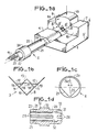
- a base 1 has a lower flat face 4 in which is formed a V-shaped groove 5 capable of receiving a corresponding contour 21 formed in a cylindrical front part 20 of a nozzle 2.
- the invention s ' generally applies to any tip that can be oriented angularly with precision, for example a cylindrical tip provided with an angular positioning groove.
- the end piece 2 has at its rear part 22 two openings 23 each of which receives an optical fiber 11 and a central flange 30 allowing it to be mounted in a end body not shown.
- the base 1 also includes an upper planar surface 7 which is set back relative to the lower planar surface 4 and connected to the latter by a vertical face 16 forming a stop.
- a V-shaped groove 3 whose walls are marked at 8.
- a calibrated wedge 10 of square section At the bottom of the groove 3, is arranged a calibrated wedge 10 of square section.
- This calibrated wedge defines on each side a V-shaped profile, one of the walls of which is constituted by a wall 8 of the groove 3 and the other wall of which is formed by one of the sides 18 of the calibrated wedge 10.
- a piece of support 15 has an upper wall 15 and two parallel side faces 14 extending downward by two inclined planes 8 'arranged so as to correspond to the profile of the groove 3.
- the inclined planes 8' do not extend to the part lower of the V 3, but only up to a horizontal face 12 in the center of which is formed a groove 13 parallel to the axis of the groove 3.
- an optical fiber 11 is arranged in the first and the second profile 19 in the form of a V delimited by the groove 3 whose faces 8 can form an angle of 90 ° between them and the wedge calibrated 10 and when the support piece 15 is in position in the groove 3, each of the two portions of the plane 12 comes into contact with the corresponding optical fiber 11.
- the groove 13 is made so that the support piece n 'is not in contact with the calibrated wedge 10.
- the calibrated wedge 10 has a chamfered edge 17 disposed on the side opposite the bottom of the groove 3, the support piece 9 having the longitudinal groove 13 at middle of its lower face 12.
- the support piece 9 abuts on the walls 8 of the V-shaped groove 3, the position of the plane 12 is determined with precision, which, taking into account the dimensions geometry of the wedge 10, allows to measure exactly the ef strongly subjected to the optical fibers 11 for their positioning by plating at the bottom of the secondary Vs.
- the crushing of the fibers thus produced will be limited to a maximum of a few microns only, so as to avoid subjecting them to stresses producing a deformation of the fibers detrimental to the accuracy of the centering.
- the plane 12 is such that a clearance of less than about 3 microns exists with the fibers, the latter then being simply guided and not plated.
- FIG. 1 represents a front view of the end piece 2.
- the faces 21 of the V-shaped contour meet by a face 25.
- the optical fibers 11 which are introduced by openings 23 in a number equal to that of the optical fibers of l end piece (here 2) located in the rear cylindrical part 22 of the end piece, open on the front face at the level of two openings 26 which, when the end piece is positioned in the groove 5 in abutment on the vertical face 16, are located respectively opposite the first and second profiles 19 in the form of a V.
- the openings 26 are preferably located, as shown, in the median plane of the nozzle.
- the installation of the optical fibers in the tip is then carried out in the following manner (see FIG. Id).
- the optical fibers 11 are introduced into the openings 23 of the end piece 2 formed in an insert 23 'and which have a diameter slightly greater than that of the optical fibers so that on the one hand they can slide freely and that on the other hand, the openings 23 carry out an axial pre-guiding of the fibers.
- the fibers 11 then pass through a chamber 33 in communication with the outside of the endpiece through an opening 24 (FIG. 1a) which flares at 32 from the openings 23 and which acts as a glue reserve and penetrate into the or the openings 26, the diameter of which is also greater than that of the fibers.
- the introduction of the fibers into the openings 26 is facilitated by the presence of the chamfers 31.
- the optical fibers protruding from the front face of the end piece 2 are then positioned in the V-shaped profiles 19 using the part d support 9 and the glue is then introduced through an opening 24 formed at the front of the upper part of the cylindrical part 20, opening 24 which is in communication with the chamber 33, so that the glue which enters the chamber filling 33, and by the play of the openings 26 is capable of holding the fibers in position.
- the choice of diameter 26 is preferably such that the adhesive penetrates by capillarity around the fibers into the openings 26, without however flowing outwards. After the glue has dried, the fibers are cut and then polished and the tip is ready to use.
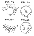
- FIG. 2a is a variant of FIG. 1b, in which the calibrated wedge 10 is replaced by a precision cylindrical rod 27.
- This solution is particularly suitable for the case where it is desired to reduce the distance between the fibers 11.
- the diameter of the cylindrical rod 27 is nominally 0.39 mm.
- a small distance between the fibers 11, for example of the order of 0.5 mm allows these to be opened by a single opening 28 disposed on the front face of the end piece 2.
- the fibers are introduced through two openings 23 formed at the rear of the end piece 2.
- FIG. 3a represents a variant making it possible to have four optical fibers in a tip comprising on its front face preferably two openings 48 and 49 each receiving a pair of optical fibers 11. It will be understood that this embodiment is also applicable to the case of a nozzle comprising three or four openings on its front face.
- a calibrated wedge such as 10, of appropriate dimensions, receives on each of its first and second V-shaped profiles a calibrated wedge, here a cylindrical rod 4 1.
- Each cylindrical rod 41 delimits secondary V-shaped profiles, each of which is such that it can receive an optical fiber.
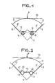
- the support piece 9 resting on the sides 8 of the groove 3, its underside has three coplanar regions, a central region 40 pressing on the two central fibers 11, and two lateral regions 42 pressing on the external optical fibers 11.
- the support piece 9 is made so that, if it came into abutment on the walls 8 of the V-shaped groove 3, the position of the plane 12 would correspond to a theoretical crushing of the fibers equal to minimum to a few microns and maximum to about 20 microns.
- the manufacturing tolerance of the support piece can allow values included in this range, thus avoiding too great precision in the production of the support piece 9.
- the support piece 9 comes in contact with the fibers 11 without its two faces 8 'being in abutment on the faces 8 of the V formed by the groove 3 and the bearing force on the fibers 11 is limited by a calibrated pressure system applying pressure on the fibers (corresponding according to a preferred embodiment to a force of the order of 500 grams maximum for a support piece 9 pressing on the fibers over a length of 20 mm) such that the crushing of these remains of l 'order of a few microns so as to maintain good alignment accuracy.
- the faces 8 'of the support piece 9 remain very close to the faces 8 of the V3.
- the faces 8 of the support piece 9 serve to limit the possible tilting of the support piece 9 under the action of the force F applied along the axis of the groove 3.
- the tilting can in addition to be largely counteracted by giving the upper face 1 5 of the support piece 9 a cylindrical profile whose axis coincides with the axis of symmetry of the fibers and by applying the force F by means of a flat part 50, which allows the force F to pass through the median plane of the two fibers.
- Figure 5 shows the same design as Figure 4, but in the case where four fibers are used.
- the invention makes it possible to have up to four optical fibers in a tip of standard dimensions usually used for centering a single optical fiber.
- This arrangement is particularly advantageous in that the realization of V-shaped contours such as 21 in a tip becomes more delicate as the dimensions of the latter increase.
Landscapes
- Physics & Mathematics (AREA)
- General Physics & Mathematics (AREA)
- Optics & Photonics (AREA)
- Mechanical Coupling Of Light Guides (AREA)
Priority Applications (1)
| Application Number | Priority Date | Filing Date | Title |
|---|---|---|---|
| EP86101542A EP0189946A3 (de) | 1982-10-08 | 1983-09-30 | Anordnungsstecker für mehrere optische Fasern |
Applications Claiming Priority (3)
| Application Number | Priority Date | Filing Date | Title |
|---|---|---|---|
| FR8216905 | 1982-10-08 | ||
| FR8216905A FR2534386A1 (fr) | 1982-10-08 | 1982-10-08 | Dispositif de montage de fibres optiques dans un embout |
| EP86101542A EP0189946A3 (de) | 1982-10-08 | 1983-09-30 | Anordnungsstecker für mehrere optische Fasern |
Related Parent Applications (2)
| Application Number | Title | Priority Date | Filing Date |
|---|---|---|---|
| EP83401928A Division EP0107989B1 (de) | 1982-10-08 | 1983-09-30 | Vorrichtung zum Montieren optischer Fasern in einer Zwinge |
| EP83401928.3 Division | 1983-09-30 |
Publications (2)
| Publication Number | Publication Date |
|---|---|
| EP0189946A2 true EP0189946A2 (de) | 1986-08-06 |
| EP0189946A3 EP0189946A3 (de) | 1987-12-02 |
Family
ID=26101679
Family Applications (1)
| Application Number | Title | Priority Date | Filing Date |
|---|---|---|---|
| EP86101542A Withdrawn EP0189946A3 (de) | 1982-10-08 | 1983-09-30 | Anordnungsstecker für mehrere optische Fasern |
Country Status (1)
| Country | Link |
|---|---|
| EP (1) | EP0189946A3 (de) |
Cited By (1)
| Publication number | Priority date | Publication date | Assignee | Title |
|---|---|---|---|---|
| EP0264108A3 (en) * | 1986-10-16 | 1988-11-09 | Siemens Aktiengesellschaft Berlin Und Munchen | Connecting element for optical waveguides |
Family Cites Families (2)
| Publication number | Priority date | Publication date | Assignee | Title |
|---|---|---|---|---|
| FR2417784A1 (fr) * | 1978-02-15 | 1979-09-14 | Fort Francois | Embout de cable optique multifibre |
| FR2408152A1 (fr) * | 1978-10-03 | 1979-06-01 | Bunker Ramo | Dispositif et procede pour aligner des fibres optiques dans un connecteur |
-
1983
- 1983-09-30 EP EP86101542A patent/EP0189946A3/de not_active Withdrawn
Cited By (2)
| Publication number | Priority date | Publication date | Assignee | Title |
|---|---|---|---|---|
| EP0264108A3 (en) * | 1986-10-16 | 1988-11-09 | Siemens Aktiengesellschaft Berlin Und Munchen | Connecting element for optical waveguides |
| US4836638A (en) * | 1986-10-16 | 1989-06-06 | Siemens Aktiengesellschaft | Connector element for light waveguides |
Also Published As
| Publication number | Publication date |
|---|---|
| EP0189946A3 (de) | 1987-12-02 |
Similar Documents
| Publication | Publication Date | Title |
|---|---|---|
| EP0107989B1 (de) | Vorrichtung zum Montieren optischer Fasern in einer Zwinge | |
| EP0005792A1 (de) | Verfahren zum Verbinden von optischen Fasern, die bandförmig in einem Kabel angeordnet sind und Vorrichtung zur Durchführung dieses Verfahrens | |
| EP0146867B1 (de) | Optischer Dämpfungsregler für Kupplung von optischen Fasern | |
| EP3102973B1 (de) | Verfahren zur herstellung vertikaler optischer kopplungsstrukturen | |
| EP0682277B1 (de) | Anordnung zur Verbindung von optischen Fasern und Wellenleitern, die auf einem Substrat angebracht sind | |
| EP1011863B1 (de) | Behälter für mehrkanal-pipettenspitzen | |
| CA2306684A1 (fr) | Assemblage d'une puce de circuit integre optique sur une plate-forme de connexion de fibres optiques, pour former un composant optique miniature | |
| EP0014656B1 (de) | Piezoelektrischer Beschleunigungsmesser | |
| FR2694419A1 (fr) | Procédé de couplage d'une fibre optique à un composant sur un substrat commun. | |
| EP0176154B1 (de) | Verfahren zur Herstellung von einem Endbestandteil für eine optische Faser und Bestandteil so erhältlich | |
| EP0189946A2 (de) | Anordnungsstecker für mehrere optische Fasern | |
| EP0234981B1 (de) | T-förmige, optische Kupplung für Anwendungen in optischen Busnetzwerken und optischer Bus, versehen mit einer Vielzahl solcher Kupplungen | |
| EP0121460A1 (de) | Aufnahmestück für optische Fasern für eine Kupplungsvorrichtung und Verfahren zur Herstellung einer solchen Vorrichtung | |
| EP0096608B1 (de) | Faseroptischer Kollimator, Anwendung zur Realisierung optischer Schaltervorrichtungen | |
| CH684217A5 (fr) | Procédé et dispositif pour aligner des fibres optiques. | |
| FR2661515A1 (fr) | Dispositif optique a composant d'optique integree et procede de fabrication. | |
| FR2823859A1 (fr) | Support de positionnement et de maintien de fibres optiques et son procede de realisation | |
| EP0068423B1 (de) | Verbindung für optische Monofasern | |
| FR2777662A1 (fr) | Procede d'assemblage d'un module optique | |
| EP0061423B1 (de) | Zentriervorrichtung für Steckverbindung von optischen Fasern | |
| EP3916441A1 (de) | Lichtverteilungsvorrichtung auf basis eines planaren wellenleiters | |
| FR2542458A1 (fr) | Procede et dispositif de raccordement de fibres optiques | |
| CA1299409C (fr) | Dispositif d'immobilisation rapide d'un element tubulaire dans un boitier d'appareillage et bloc de jonction pour fibres optiques dote d'untel dispositif | |
| FR2459987A1 (fr) | Dispositif et procede pour fabriquer des pieces d'un repartiteur optique | |
| WO2002071102A2 (fr) | Element de maintien et d'indexation d'une structure guidante asymetrique |
Legal Events
| Date | Code | Title | Description |
|---|---|---|---|
| PUAI | Public reference made under article 153(3) epc to a published international application that has entered the european phase |
Free format text: ORIGINAL CODE: 0009012 |
|
| 17P | Request for examination filed |
Effective date: 19860208 |
|
| AC | Divisional application: reference to earlier application |
Ref document number: 107989 Country of ref document: EP |
|
| AK | Designated contracting states |
Kind code of ref document: A2 Designated state(s): DE GB IT |
|
| PUAL | Search report despatched |
Free format text: ORIGINAL CODE: 0009013 |
|
| AK | Designated contracting states |
Kind code of ref document: A3 Designated state(s): DE GB IT |
|
| 17Q | First examination report despatched |
Effective date: 19910418 |
|
| STAA | Information on the status of an ep patent application or granted ep patent |
Free format text: STATUS: THE APPLICATION IS DEEMED TO BE WITHDRAWN |
|
| 18D | Application deemed to be withdrawn |
Effective date: 19910925 |
|
| RIN1 | Information on inventor provided before grant (corrected) |
Inventor name: BERTHO, DOMINIQUE Inventor name: PARCHET, PIERRE |