EP0189548A1 - Procedure for the copy-protected magnetic recording of video signals - Google Patents
Procedure for the copy-protected magnetic recording of video signals Download PDFInfo
- Publication number
- EP0189548A1 EP0189548A1 EP85115099A EP85115099A EP0189548A1 EP 0189548 A1 EP0189548 A1 EP 0189548A1 EP 85115099 A EP85115099 A EP 85115099A EP 85115099 A EP85115099 A EP 85115099A EP 0189548 A1 EP0189548 A1 EP 0189548A1
- Authority
- EP
- European Patent Office
- Prior art keywords
- signal
- video signal
- video
- recorded
- interference
- Prior art date
- Legal status (The legal status is an assumption and is not a legal conclusion. Google has not performed a legal analysis and makes no representation as to the accuracy of the status listed.)
- Withdrawn
Links
Images

Classifications
-
- G—PHYSICS
- G11—INFORMATION STORAGE
- G11B—INFORMATION STORAGE BASED ON RELATIVE MOVEMENT BETWEEN RECORD CARRIER AND TRANSDUCER
- G11B20/00—Signal processing not specific to the method of recording or reproducing; Circuits therefor
- G11B20/00086—Circuits for prevention of unauthorised reproduction or copying, e.g. piracy
- G11B20/00731—Circuits for prevention of unauthorised reproduction or copying, e.g. piracy involving a digital rights management system for enforcing a usage restriction
- G11B20/00818—Circuits for prevention of unauthorised reproduction or copying, e.g. piracy involving a digital rights management system for enforcing a usage restriction wherein the usage restriction limits the signal quality, e.g. by low-pass filtering of audio signals or by reducing the resolution of video signals
- G11B20/00826—Circuits for prevention of unauthorised reproduction or copying, e.g. piracy involving a digital rights management system for enforcing a usage restriction wherein the usage restriction limits the signal quality, e.g. by low-pass filtering of audio signals or by reducing the resolution of video signals wherein a spoiler signal is added to degrade the signal quality
-
- G—PHYSICS
- G11—INFORMATION STORAGE
- G11B—INFORMATION STORAGE BASED ON RELATIVE MOVEMENT BETWEEN RECORD CARRIER AND TRANSDUCER
- G11B20/00—Signal processing not specific to the method of recording or reproducing; Circuits therefor
- G11B20/00086—Circuits for prevention of unauthorised reproduction or copying, e.g. piracy
-
- H—ELECTRICITY
- H04—ELECTRIC COMMUNICATION TECHNIQUE
- H04N—PICTORIAL COMMUNICATION, e.g. TELEVISION
- H04N5/00—Details of television systems
- H04N5/76—Television signal recording
- H04N5/91—Television signal processing therefor
- H04N5/913—Television signal processing therefor for scrambling ; for copy protection
- H04N2005/91307—Television signal processing therefor for scrambling ; for copy protection by adding a copy protection signal to the video signal
- H04N2005/91314—Television signal processing therefor for scrambling ; for copy protection by adding a copy protection signal to the video signal the copy protection signal being a pulse signal inserted in blanking intervals of the video signal, e.g. pseudo-AGC pulses, pseudo-sync pulses
-
- H—ELECTRICITY
- H04—ELECTRIC COMMUNICATION TECHNIQUE
- H04N—PICTORIAL COMMUNICATION, e.g. TELEVISION
- H04N5/00—Details of television systems
- H04N5/76—Television signal recording
- H04N5/91—Television signal processing therefor
- H04N5/913—Television signal processing therefor for scrambling ; for copy protection
- H04N2005/91357—Television signal processing therefor for scrambling ; for copy protection by modifying the video signal
- H04N2005/91371—Television signal processing therefor for scrambling ; for copy protection by modifying the video signal the video color burst signal being modified
Definitions
- a major advantage is that according to the inventive method, a video signal is optimally influenced or pre-distorted, deformed and weighted in such a way that the automatic control and capture mechanisms of a recorder used for the first or 'allowed' playback result in a correct video signal and that the rule - And automatic capture of a second video recorder, which is used to make a pirated copy, certainly only allow a disturbed video signal.
Landscapes
- Engineering & Computer Science (AREA)
- Signal Processing (AREA)
- Multimedia (AREA)
- Computer Security & Cryptography (AREA)
- Television Signal Processing For Recording (AREA)
- Signal Processing Not Specific To The Method Of Recording And Reproducing (AREA)
- Signal Processing For Digital Recording And Reproducing (AREA)
Abstract
Description
Die vorliegende Erfindung betrifft ein Verfahren zur Herstellung von kopiergeschützten magnetischen Aufzeichnungsträgern nach dem Oberbegriff des Patentanspruches 1.The present invention relates to a method for producing copy-protected magnetic recording media according to the preamble of
Aus der US-PS 41 63 253 ist ein Verfahren zum Schutz vor Raubkopien bekannt, bei dem ein Videosignal dadurch verändert wird, daß ein Impuls in das Austastintervall des Videosignales eingefügt wird, dessen Amplitude im wesentlichen gleich dem Weiß-Spitzenpegel des Videosignales ist. Wenn das derart modifizierte Videosignal beim unerlaubten Überspielvorgang auf einem herkömmlichen Videorekorder aufgezeichnet wird, wird der zuvor eingefügte Impuls durch den AGC-Detektor des Videorekorders nachgewiesen. Der Detektor bewirkt dann, daß der ACC-Verstärker das Video- . signal vor der Aufzeichnung derart schwächt, daß eine unbrauchbare Aufnahme entsteht.From US-PS 41 63 253 a method for protection against piracy is known, in which a video signal is changed by inserting a pulse into the blanking interval of the video signal, the amplitude of which is substantially equal to the white peak level of the video signal. If the video signal thus modified is recorded on a conventional video recorder during the unauthorized dubbing process, the previously inserted pulse is detected by the AGC detector of the video recorder. The detector then causes the ACC amplifier to video. signal weakens before the recording so that an unusable recording occurs.
Ein Nachteil eines derartigen Verfahrens besteht darin, daß es durch relativ einfache Eingriffe am Videorekorder, mit dem Raubkopien hergestellt werden, außer Funktion gesetzt werden kann, weil der Videorekorder durch derartige Eingriffe für die eingefügten Impulse unempfindlich gemacht werden kann.A disadvantage of such a method is that it can be disabled by relatively simple interventions on the video recorder with which pirated copies are made, because the video recorder can be made insensitive to the inserted pulses by such interventions.
Die Aufgabe der vorliegenden Erfindung besteht daher darin, ein Verfahren zur Herstellung von kopiergeschützten magnetischen Aufzeichnungsträgern anzugeben, durch das zuverlässig gestörte Aufzeichnungsergebnisse durch den zur Erzeugung von Raubkopien verwendeten Videorekorder erreicht werden, ohne daß es möglich ist, das Verfahren durch Manipulationen am Videorecorder außer Betrieb bzw. Funktion zu setzen.The object of the present invention is therefore to provide a method for producing copy-protected magnetic recording media, can be achieved by the reliably disturbed recording results by the video recorder used to generate pirated copies, without it being possible to put the method out of operation or function by manipulations on the video recorder.
Diese Aufgabe wird durch ein Verfahren der eingangs genannten Art gelöst, das durch die in dem kennzeichnenden Teil des Patentanspruches 1 angeführten Merkmale gekennzeichnet isti.This object is achieved by a method of the type mentioned, which is characterized by the features stated in the characterizing part of
Ein wesentlicher Vorteil besteht darin, daß nach dem erfindungsgemäßen Verfahren ein Videosignal optimal derart beeinflußt bzw. vorverzerrt, verformt und gewichtet wird, daß die Regel- und Fangautomatiken eines zur ersten bzw. 'erlaubten' Wiedergabe verwendeten Rekorders ein korrektes Videosignal ergeben und daß die Regel- und Fangautomatiken eines zweiten Videorekorders, der zur Anfertigung einer Raubkopie verwendet wird, sicher nur noch ein gestörtes Videosignal zulassen.A major advantage is that according to the inventive method, a video signal is optimally influenced or pre-distorted, deformed and weighted in such a way that the automatic control and capture mechanisms of a recorder used for the first or 'allowed' playback result in a correct video signal and that the rule - And automatic capture of a second video recorder, which is used to make a pirated copy, certainly only allow a disturbed video signal.
Vorteilhafterweise arbeitet das erfindungsgemäße Verfahren nach dem Prinzip des sogenannten 'Worst-Case'. Dies bedeutet, daß für die Gesamtzahl vorgegebener Aufzeichnugnsparameter optimale Toleranz- und Störgrößenkriterien ermittelt werden, die mit handelsüblichen Geräten bei der ersten Übertragung jeweils ein korrektes und bei der nachfolgenden zweiten Übertragung ein sicher gestörtes Aufzeichnungsergebnis liefern. Das vorliegende Verfahren kann vorteilhafterweise im Zusammenhang mit allen üblichen Videosystemen (z.B. VHS, V 2000, Betamax) angewendet werden.The method according to the invention advantageously works on the principle of the so-called 'worst case'. This means that for the total number of specified recording parameters, optimal tolerance and disturbance variable criteria are determined, which with commercially available devices each have a correct recording result during the first transmission and a reliably disturbed recording result during the subsequent second transmission deliver. The present method can advantageously be used in connection with all conventional video systems (eg VHS, V 2000, Betamax).
Ein weiterer wesentlicher Vorteil der vorliegenden Erfindung besteht darin, daß es nicht erforderlich ist, zusätzliche Hilfssignale in das Videosignal einzubringen. Derartige Hilfssignale haben nämlich den Nachteil, daß sie sehr leicht erkennbar sind. Aus diesem Grunde können verhältnismäßig leicht Maßnahmen ergriffen werden, die bei der Anfertigung von Raubkopien zur Beseitigung dieser Hilfssignale führen. Im Gegensatz dazu sind die am Videosignal erfindungsgemäß vorgenommenen Modifikationen nicht erkennbar und so vielfältig, daß es unmöglich ist, Gegenmaßnahmen zu ergreifen.Another important advantage of the present invention is that it is not necessary to introduce additional auxiliary signals in the video signal. Such auxiliary signals have the disadvantage that they are very easy to recognize. For this reason, it is relatively easy to take measures that lead to the elimination of these auxiliary signals when pirated copies are made. In contrast, the modifications made to the video signal according to the invention are not recognizable and so diverse that it is impossible to take countermeasures.
Im folgenden wird das erfindungsgemäße Verfahren im Zusammenhang mit den Figuren näher erläutert.The method according to the invention is explained in more detail below in connection with the figures.
Es zeigt:
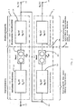
Figur 1 ein Blockschaltbild zur Erläuterung der Erfindung; undFiguren 2 und 3 Videosignale zur Erläuterung der Erfindung
- Figure 1 is a block diagram for explaining the invention; and
- Figures 2 and 3 video signals to explain the invention
In der Figur 1 bezeichnet der Block 1 einen Videorekorder, wie er beispielsweise zur Anfertigung einer ersten Kopie oder zur Wiedergabe dieser ersten Kopie verwendet wird. Dabei wird dem Videorecorder 1 aus dem sogenannten MAZ-Gerät (magnetisches Aufzeichnungsgerät für die Mutter- bzw. Masterkopie) das Eingangssignal x(t) an einem Eingang 11 zugeführt. Vom Eingang 11 wird das Eingangssignal einem Codierer 12 zur Durchführung der Aufnahmecodierung zugeführt. Das durch den Codierer 12 kodierte Signal wird auf einem Videoband 13 aufgezeichnet. Vom Videoband 13 wird das aufgezeichnete Signal einem Wiedergabe-Decodierer 14 zugeführt, an dessem Ausgang, der gleichzeitig den Ausgang 15 des Videorecorders 1 bildet, das erste Wiedergabesignal wl(t) erzeugt wird. An das erste Wiedergabesignal wl(t) wird die Anforderung gestellt, daß es in jedem Falle das Eingangssignal x(t) korrekt wiedergibt. Anders ausgedrückt, muß das erste Wiedergabesignal wl(t) der Originalaufzeichnung entsprechen.In FIG. 1,
Normalerweise handelt es sich bei dem Codierer 12 des Blocks 1 um, eine Standardfunktionsgruppe zur Aufnahme-Codierung in einem kopierenden Videorekorder, mit dem erlaubte Kopien auf Videobändern 13 hergestellt werden. Bei dem Decodierer 14 des Blocks 1 handelt es sich normalerweise um eine Standardfunk- tionsgruppe zur Wiedergabe-Codierung in einem Videorekorder 1, mit dem gekaufte oder gemietete Videobänder 13 wiedergegeben werden. In der Figur 1 ist die mögliche örtliche Trennung des Codierers 12 und des Decodierers 14 durch die Linie 30 angedeutet.The
In der Figur 1 bezeichnet der Block 2 einen zweiten Videorekorder, wie er beispielsweise zur Anfertigung von Raubkopien eingesetzt wird. Zu diesem Zweck wird einem derartigen Videorekorder 2 das erste Wiedergabesignal wl(t) des Videorekorders 1 am Eingang 21 zugeführt. Das am Eingang 21 zugeführte erste Wiedergabesignal wl(t) wird bei der Anfertigung einer Raubkopie durch den Aufnahme-Codierer 22 des Videorekorders 2 kodiert und auf einem Videoband 23 aufgezeichnet. Dieses Videoband 23 stellt die Raubkopie dar. Bei der Wiedergabe der Raubkopie wird das auf dem Band 23 aufgezeichnete Videosignal durch einen Wiedergabe-Decodierer 23 dekodiert und dem Ausgang 25 des Videorekorders 2 als zweites Wiedergabesignal w2(t) zugeführt. An das zweite Wiedergabesignal w2(t) wird die Anforderung gestellt, daß es derartig gestört bzw. verzerrt ist, daß es keine akzeptable Wiedergabe des Eingangssignales x(t) des MAZ-Gerätes bzw. keine akzeptable Wiedergabe der Originalaufzeichnung darstellt.In FIG. 1,
Der Aufnahme-Codierer 22 des Blocks 2 befindet sich in Kopiergeräten, die zur Aufzeichnung von Raubkopien auf Bändern 23 verwendet werden. Der Wiedergabe-Codierer 24 befindet sich normalerweise in Videorekordern, die zur Wiedergabe von auf Bändern 23 aufgezeichneten Videosignalen verwendet werden.The
Die vorliegende Erfindung beruht auf der Erkenntnis, daß im Zusammenhang mit einem wirkungsvollen Kopierschutz eine besondere Schwierigkeit darin besteht, daß ab dem Eingang 11 des Videorekorders 1, der hinter dem MAZ-Gerät angeordnet ist, bis zum Ausgang 25 des zur Wiedergabe einer Raubkopie verwendeten Videorekorders 2 oder bis zum Ausgang weiterer nachgeschalteter Videorekorder kein Systemparameter zugänglich ist. Die Erfindung beruht daher darauf, daß das Eingangssignal x(t) in einer definierten Weise unter optimaler Ausnutzung der festen System-Charakteristiken der handelsüblichen Videorekorder modifiziert wird.The present invention is based on the knowledge that, in connection with effective copy protection, there is a particular difficulty in that from the
Zum besseren Verständnis wird zunächst auf die im folgenden verwendeten Nomenklatur hingewiesen:
- v(t) = Aufzeichnungssignal (FBAS, Audio),
- k(t) = Skalierungsfunktion,
- n(t) - Störsignal,
- wi(t) = Wiedergabesignal (am Ausgang 15) der Originalaufzeichnung,
- w2(t) = Wiedergabesignal (am Ausgang 25) der zweiten Kopie,
- w1(p), W2(p) = zugehörige Frequenz-Spektren
- hA(t) = Impulsantwort des Videorekoder-Aufnahme-Kanals,
- hw(t) = Impulsantwort des Videorekorder-Wiedergabekanals,
- HA(p), Hw(p) zugehörige Übertragungsfunktion
- GB AW = Frequenzfunktion des Magnetkanals vom Schreib- bis zum Lesevorgang, Index "B" = Band Index "AW" = Aufnahme-Wiedergabe.
- v (t) = recording signal (CVBS, audio),
- k (t) = scaling function,
- n (t) - interference signal,
- w i (t) = playback signal (at output 15) of the original recording,
- w 2 (t) = playback signal (at output 25) of the second copy,
- w 1 (p), W 2 ( p ) = associated frequency spectra
- h A (t) = impulse response of the video recorder recording channel,
- h w (t) = impulse response of the video recorder playback channel,
- H A (p), H w (p) associated transfer function
- G B A W = frequency function of the magnetic channel from writing to reading, index "B" = tape index "AW" = recording playback.
Aufgrund der nichtlinearen, zeitvarianten und pseudokausalen Eigenschaften des Magnetkanals wurde GB AW nicht als "Übertragungsfunktion" bezeichnet.Due to the non-linear, time-variant and pseudo-causal properties of the magnetic channel, G B A W was not called a "transfer function".
Das nach dem vorliegenden Verfahren modifizierte Eingangssignal am Anschluß 11 läßt sich durch die folgende Gleichung ausdrücken:![]()
![]()
Dabei stellen k(t) eine Skalierungsfunktion und n(t) ein Störsignal dar, die in Abhängigkeit von der Kenntnis der spezifischen Funktionsweise der handelsüblichen Videorekorder (VHS-,Beta- und V 2000-Rekorder) durch Beeinflussung sämtlicher möglicher Signalparameter derart optimal zu beeinflussen sind, daß das Aufzeichnungssignal v(t) im ersten Wiedergabesignal wi(t) am Ausgang 15 des Videorekorders 1 optimal wiedergewonnen wird und daß das Aufzeichnungssignal v(t) im zweiten Wiedergabesignal w2(t) für eine Betrachtung unbrauchbar ist. Dabei bieten die praktischen Video-Codierungsverfahren für die Wiedergabe zur Beeinflussung ein gut nutzbares Kriterium, das vom jeweiligen Magnetkanal und von allen nicht idealen, beispielsweise nicht linearen Systemparametern abhängt. Das vorliegende Verfahren nutzt den sogenannten Multi-Parameter-Worst-Case. Dies bedeutet, daß die Skalierungsfunktion k(t) und die Störgröße n(t) so bestimmt werden, daß die zweite Aufnahme zur Anfertigung einer Raubkopie auch durch den Videorekorder 2 sicher gestört wird, der auf die Skalierungsfunktion k(t) und die Störgröße n(t) am schlechtesten anspricht.Here, k (t) is a scaling function and n (t) is an interference signal which, depending on the knowledge of the specific functioning of the commercially available Video recorders (VHS, Beta and V 2000 recorders) can be optimally influenced by influencing all possible signal parameters such that the recording signal v (t) in the first playback signal w i (t) is optimally recovered at the
Zur Ermittlung der anzuwendenden Skalierungsfunktion k(t) und der anzuwendenden Störgröße n(t) wird das Impulsübertragungsverhalten zweier gemäß der Figur hintereinandergeschalteter Videorekorder bzw. Kopiergeräte untersucht. Dabei gilt für das Frequenzspektrum des ersten Videorekorders 1:
Für das Frequenzspektrum des zweiten Videorekorders 2 gilt entsprechend:
Es ist ersichtlich, daß entsprechend einer ersten Näherung von einer Quadratur der Bildfunktion im Spektralbereich ausgegangen werden kann. Zusätzlich unterliegt die tatsächliche Signalkette Unterscheidungsmerkmalen, die durch die Charakteristik des Magnetkanals (Videoband) bewirkt werden.It can be seen that a quadrature of the image function in the spectral range can be assumed according to a first approximation. In addition, the actual signal chain is subject to distinctive features that are caused by the characteristics of the magnetic channel (video tape).
Erfindungsgemäß werden die Größen HA(P) und HW(p) durch Prüfung eienr repräsentativen Anzahl von Videorekordern eines Systems (z.B. VHS, V 2000, Betamax) bestimmt. Hierzu wird jeweils die numerische Impulsantwort h(t) für die Aufnahmecodierer 12, das Band 13 und den Wiedergabe-Decodierer 14 dadurch ermittelt, daß an die jeweiligen Eingänge ein Testsignal x'(t) angelegt wird und in Antwort darauf an den jeweiligen Ausgängen ein Antwortsignal y'(t) ermittelt wird. Die jeweiligen Testsignale x(t) und die entsprechenden Antwortsignale y'(t) werden durch rechnermäßige bzw. computergestützte Laplace-Transformationen in die entsprechenden Spektren X'(p) (Eingang) und Y'(p) (Ausgang) umgewandelt. Nach der Formel H'(p) = Y'(p) / X'(p) ergeben sich dann die entsprechenden Übertragungsfunktionen Y'(p), aus denen durch erneute rechnermäßige bzw. computergestützte Laplace-Transformationen die numerischen Impulsantworten, die für die entsprechenden Geräte spezifisch sind, ermittelt werden können.According to the invention, the variables H A ( P ) and H W (p) are determined by checking a representative number of video recorders in a system (for example VHS, V 2000, Betamax). For this purpose, the numerical impulse response h (t) for the
Alle Operationen im Zeit- und Frequenzbereich bedingen aufgrund der erheblichen Komplexität des Aufzeichnungs-und Wiedergabekanals eines Videorekorders grundsätzlich die numerische Bestimmung der Zeit- und Bildfunktionen durch ein Computersystem.Conduct all operations in the time and frequency domain due to the considerable complexity of the recording and playback channel of a video recorder, the numerical determination of the time and image functions by a computer system.
Nach Kenntnis der Übertragungsfunktionen des ersten und zweiten Videorekorders 1, 2 ist es nun möglich, mit der Hilfe der mathematischen Faltung jeweils die Antwortsignale wl(t), w2(t) aus den Eingangssignalen x(t), wl(t) und den Übertragungsfunktionen yi(t), y2(t) zu bestimmen. Die mathematischen Formeln hierfür lauten:

Die störenden Parametermaßnahmen betreffen dabei wertmäßige, zeitmäßige und frequenzspezifische Charakteristiken. Beispielsweise können Hüllkurven von Signalparametern durch Skalierungsfunktionen verändert werden, wobei diese Veränderungen sich vorteilhafterweise auch fortlaufend zeitlich verändern können. Derartig veränderbare Hüllkurven können auch durch Addition und/oder Subtraktion von Störsignalen zusätzlich modifiziert werden, wobei sich diese Störsignale vorteilhafterweise ebenfalls fortlaufend zeitlich verändern können.The disruptive parameter measures relate to value-based, timely and frequency-specific characteristics. For example, envelope curves of signal parameters can be changed by scaling functions, whereby these changes can advantageously also change continuously over time. Envelopes that can be changed in this way can also be additionally modified by adding and / or subtracting interference signals, wherein these interference signals can advantageously also change continuously over time.
Signalparameter können durch Skalierungsfunktionen auch bezüglich ihrer Phase verändert werden, so daß eine zeitliche Drift dieser Signalparameter bewirkt wird. Dabei können sich derartige Phasenänderungen ebenfalls fortlaufend zeitlich verändern.Signal parameters can also be changed with regard to their phase by scaling functions, so that a temporal drift of these signal parameters is brought about. Such phase changes can also change continuously over time.
An Signalparametern können durch Skalierungsfunktionen auch Frequenzänderungen bewirkt werden. Derartige Frequenzfehler können sich vorteilhafterweise auch fortlaufend zeitlich ändern.Frequency changes in signal parameters can also be effected by scaling functions. Such frequency errors can advantageously also change continuously over time.
Die zuvorgenannten Skalierungsfunktionen und ggf. auch die genannten Störfaktoren können zusammen oder getrennt auf eine beliebige Anzahl von jeweils geeigneten Signalparamtern des Videosignals des MAZ-Gerätes einwirken. Es ist dabei lediglich von Bedeutung, daß an dem ersten kopierten Videosignal und an dem zweiten kopierten Videosignal die jeweils gewünschten Wirkungen eintreten, die voranstehend bereits erläutert wurden.The aforementioned scaling functions and possibly also the mentioned interference factors can act together or separately on any number of suitable signal parameters of the video signal of the MAZ device. It is only important that the desired effects occur on the first copied video signal and on the second copied video signal, which effects have already been explained above.
Im folgenden wird im Zusammenhang mit den Figuren 2 und 3 eine Übersicht über zur Parameterbeeinflussung vorgesehenen Signalgrößen gegeben.In the following, in connection with FIGS. 2 and 3, an overview of signal quantities provided for influencing parameters is given.
Es werden die Phasen- und Frequenzfehler des Burst-Signales 31 (Farbfrequenzsignal) bewirkt. Dabei können diese bewirkten Fehler sich vorteilhafterweise auch zeitlich verändern, d.h. also beispielsweise eine lineare Frequenz- und Phasenmodulation darstellen.The phase and frequency errors of the burst signal 31 (color frequency signal) are brought about. These errors can also advantageously change over time, i.e. thus represent, for example, a linear frequency and phase modulation.
Es wird die in der Figur 2 geradlinig verlaufende Hüllkurve 32 durch eine beliebige Zeitfunktion ersetzt. Beispielsweise sind in dieser zeitlichen Variation auch zusätzliche Störsignale enthalten.The
Zur Verformung kommen alle möglichen, die Einhüllende des H-Synchronimpulses 33 verändernden Störsignale in Frage.All possible interference signals that change the envelope of the H
Es werden Phasenfehler, die einer zeitlichen Drift entsprechen, bewirkt. Dabei können diese bewirkten Fehler sich vorteilhafterweise fortlaufend zeitlich verändern, d.h. also beispielsweise eine lineare Phasenmodulation darstellen.There are phase errors that are temporal Correspond to drift. The errors caused can advantageously change continuously over time, that is to say, for example, represent a linear phase modulation.
Der Verformung kommen alle möglichen, die Einhüllende des V-Synchronimpulses 35, 36 verändernden Störsignle in Frage.The deformation is subject to all possible interference signals that change the envelope of the V synchronous pulse 35, 36.
Es werden Phasenfehler, die einer zeitlichen Drift entsprechen, bewirkt. Dabei können diese bewirkten Fehler sich vorteilhafterweise auch fortlaufend zeitlich verändern, d.h. also beispielsweise eine lineare Phasenmodulation darstellen.Phase errors corresponding to a temporal drift are caused. The errors caused can advantageously also change continuously over time, i.e. thus represent, for example, a linear phase modulation.
Störung der DTF-Frequenzen beim System V 2000Disturbance of the DTF frequencies in the System V 2000
Diese Störungen betreffen die dynamische Spurverfolgung (Dynamic Track Follow)These disorders affect dynamic track follow
Claims (15)
Applications Claiming Priority (2)
| Application Number | Priority Date | Filing Date | Title |
|---|---|---|---|
| DE3443857 | 1984-11-30 | ||
| DE19843443857 DE3443857A1 (en) | 1984-11-30 | 1984-11-30 | METHOD FOR PRODUCING COPY-PROTECTED MAGNETIC RECORDING CARRIERS |
Publications (1)
| Publication Number | Publication Date |
|---|---|
| EP0189548A1 true EP0189548A1 (en) | 1986-08-06 |
Family
ID=6251649
Family Applications (1)
| Application Number | Title | Priority Date | Filing Date |
|---|---|---|---|
| EP85115099A Withdrawn EP0189548A1 (en) | 1984-11-30 | 1985-11-28 | Procedure for the copy-protected magnetic recording of video signals |
Country Status (4)
| Country | Link |
|---|---|
| EP (1) | EP0189548A1 (en) |
| JP (1) | JPS61269472A (en) |
| DE (1) | DE3443857A1 (en) |
| ES (1) | ES8801971A1 (en) |
Cited By (4)
| Publication number | Priority date | Publication date | Assignee | Title |
|---|---|---|---|---|
| WO1991016791A1 (en) * | 1990-04-20 | 1991-10-31 | Copyguard Enterprises S.A. | A method and an apparatus for preventing unauthorized copying of video signals on tape |
| GB2267598A (en) * | 1992-06-01 | 1993-12-08 | Macrovision Uk Limited | Detecting copied video recordings |
| WO1994027406A2 (en) * | 1993-05-17 | 1994-11-24 | Macrovision Corporation | Video copy protection process enhancement to introduce horizontal and vertical picture distortions |
| AU702667B2 (en) * | 1993-05-17 | 1999-02-25 | Rovi Solutions Corporation | Video copy protection process enhancement to introduce horizontal and vertical picture distortions |
Citations (2)
| Publication number | Priority date | Publication date | Assignee | Title |
|---|---|---|---|---|
| US4163253A (en) * | 1976-03-23 | 1979-07-31 | Sony Corporation | Method of and apparatus for modifying a video signal to prevent unauthorized recording and reproduction thereof |
| DE2924453A1 (en) * | 1979-06-18 | 1981-01-15 | Walter Ing Grad Breu | Copy-proof video cassette - alters chromatic signal without affecting luminance signal by burst signal phase shift |
-
1984
- 1984-11-30 DE DE19843443857 patent/DE3443857A1/en not_active Withdrawn
-
1985
- 1985-11-28 EP EP85115099A patent/EP0189548A1/en not_active Withdrawn
- 1985-11-29 JP JP60269193A patent/JPS61269472A/en active Pending
- 1985-11-29 ES ES549440A patent/ES8801971A1/en not_active Expired
Patent Citations (2)
| Publication number | Priority date | Publication date | Assignee | Title |
|---|---|---|---|---|
| US4163253A (en) * | 1976-03-23 | 1979-07-31 | Sony Corporation | Method of and apparatus for modifying a video signal to prevent unauthorized recording and reproduction thereof |
| DE2924453A1 (en) * | 1979-06-18 | 1981-01-15 | Walter Ing Grad Breu | Copy-proof video cassette - alters chromatic signal without affecting luminance signal by burst signal phase shift |
Cited By (21)
| Publication number | Priority date | Publication date | Assignee | Title |
|---|---|---|---|---|
| WO1991016791A1 (en) * | 1990-04-20 | 1991-10-31 | Copyguard Enterprises S.A. | A method and an apparatus for preventing unauthorized copying of video signals on tape |
| US5481608A (en) * | 1990-04-20 | 1996-01-02 | Copyguard Enterprises | Method and an apparatus for preventing unauthorized copying of video signals on tape |
| GB2267598B (en) * | 1992-06-01 | 1995-09-13 | Macrovision Uk Limited | Improvements in or relating to detecting copied video recordings |
| GB2267598A (en) * | 1992-06-01 | 1993-12-08 | Macrovision Uk Limited | Detecting copied video recordings |
| EP0923240A1 (en) * | 1993-05-17 | 1999-06-16 | Macrovision Corporation | Video copy protection process enhancement |
| AU710279B2 (en) * | 1993-05-17 | 1999-09-16 | Rovi Solutions Corporation | Video copy protection process enhancement to introduce horizontal and vertical picture distortions |
| US5583936A (en) * | 1993-05-17 | 1996-12-10 | Macrovision Corporation | Video copy protection process enhancement to introduce horizontal and vertical picture distortions |
| AU702667B2 (en) * | 1993-05-17 | 1999-02-25 | Rovi Solutions Corporation | Video copy protection process enhancement to introduce horizontal and vertical picture distortions |
| AU702665B2 (en) * | 1993-05-17 | 1999-02-25 | Rovi Solutions Corporation | Video copy protection process enhancement to introduce horizontal and vertical picture distortions |
| AU702568B2 (en) * | 1993-05-17 | 1999-02-25 | Rovi Solutions Corporation | Video copy protection process enhancement to introduce horizontal and vertical picture distortions |
| WO1994027406A2 (en) * | 1993-05-17 | 1994-11-24 | Macrovision Corporation | Video copy protection process enhancement to introduce horizontal and vertical picture distortions |
| AU708661B2 (en) * | 1993-05-17 | 1999-08-12 | Rovi Solutions Corporation | Video copy protection process enhancement to introduce horizontal and vertical picture distortions |
| AU710403B2 (en) * | 1993-05-17 | 1999-09-16 | Rovi Solutions Corporation | Video copy protection process enhancement to introduce horizontal and vertical picture distortions |
| WO1994027406A3 (en) * | 1993-05-17 | 1995-01-19 | Macrovision Corp | Video copy protection process enhancement to introduce horizontal and vertical picture distortions |
| US6285765B1 (en) | 1993-05-17 | 2001-09-04 | Macrovision Corporation | Method and apparatus for reducing effects of copy protection of composite video signal |
| US6501842B2 (en) | 1993-05-17 | 2002-12-31 | Macrovision Corporation | Method and apparatus for modifying a video signal by back porch lowering |
| US7085380B2 (en) | 1993-05-17 | 2006-08-01 | Macrovision Corporation | Method for modifying a copy protected video signal with a negative amplitude pulse |
| US7352863B2 (en) | 1993-05-17 | 2008-04-01 | Macrovision Corporation | Copy protection for video signal using narrowed horizontal synchronization signals and amplitude modulation |
| US7492896B2 (en) | 1993-05-17 | 2009-02-17 | Macrovision Corporation | Copy protection for video signal using added negative amplitude pulse |
| US7620178B2 (en) | 1993-05-17 | 2009-11-17 | Macrovision Corporation | Copy protection for video signal added pulses |
| US7706533B2 (en) | 1993-05-17 | 2010-04-27 | Macrovision Corporation | Copy protection for video signal using narrowed horizontal synchronization signals |
Also Published As
| Publication number | Publication date |
|---|---|
| DE3443857A1 (en) | 1986-06-05 |
| ES549440A0 (en) | 1988-03-01 |
| ES8801971A1 (en) | 1988-03-01 |
| JPS61269472A (en) | 1986-11-28 |
Similar Documents
| Publication | Publication Date | Title |
|---|---|---|
| DE69328909T2 (en) | Transmission, recording and playback of a video signal | |
| DE69419739T2 (en) | COPY PROTECTION FOR HYBRID DIGITAL RECORDING FROM VIDEO TO TAPE | |
| DE68922658T2 (en) | Double deck video recorder and method. | |
| DE69130776T2 (en) | METHOD AND DEVICE FOR SWITCHING OFF AN ANTI-COPY PROTECTION SYSTEM IN VIDEO SIGNALS | |
| DE69829598T2 (en) | Duplication control of an information signal | |
| DE2943174C2 (en) | Device for correcting errors in the time base of video signals | |
| DE68928444T2 (en) | DOUBLE-DECK VIDEO CASSETTE STORAGE SYSTEM | |
| DE3787124T2 (en) | Magnetic recording and / or reproducing apparatus with modes with different carrier frequencies. | |
| DE3134737C2 (en) | ||
| DE3143184A1 (en) | METHOD AND DEVICE FOR SIGNAL RECORDING AND / OR PLAYBACK | |
| DE3342762C3 (en) | VIDEO SIGNAL RECORDING AND PLAYBACK DEVICE | |
| DE3788020T3 (en) | Method and device for preventing the copying of a video program. | |
| DE69317681T2 (en) | Data transmission device and data reproduction device | |
| DE3144216A1 (en) | "DISK RECORDING SYSTEM USING SIGNAL REDUNDANCY | |
| DE3126232A1 (en) | DEVICE FOR PLAYING BACK AN INFORMATION SIGNAL RECORDER | |
| DE69032737T2 (en) | Encoding and decoding device suitable for copying data | |
| DE3855568T2 (en) | Method for copy protection of a pre-recorded video tape | |
| DE2435987B2 (en) | Device for reproducing a video signal recorded on a recording medium | |
| DE69322015T2 (en) | Automatic phase adjustment circuit for a clock signal | |
| DE69033249T2 (en) | Video signal recording and playback device | |
| WO1992016944A1 (en) | Recording and/or copying system | |
| EP0189548A1 (en) | Procedure for the copy-protected magnetic recording of video signals | |
| DE69227742T2 (en) | Arrangement for obtaining tape-shaped recorded magnetic recording media, with the arrangement of received recording media, and playback device for reproducing the recording medium | |
| DE69512988T2 (en) | Method and device for copying a tape and for switching on a copy protection signal | |
| DE2036685A1 (en) | Circuit arrangement for compensating incorrect or missing parts of a WM information signal |
Legal Events
| Date | Code | Title | Description |
|---|---|---|---|
| PUAI | Public reference made under article 153(3) epc to a published international application that has entered the european phase |
Free format text: ORIGINAL CODE: 0009012 |
|
| AK | Designated contracting states |
Kind code of ref document: A1 Designated state(s): AT BE CH DE FR GB IT LI LU NL SE |
|
| 17P | Request for examination filed |
Effective date: 19870122 |
|
| 17Q | First examination report despatched |
Effective date: 19881123 |
|
| STAA | Information on the status of an ep patent application or granted ep patent |
Free format text: STATUS: THE APPLICATION IS DEEMED TO BE WITHDRAWN |
|
| 18D | Application deemed to be withdrawn |
Effective date: 19890404 |
|
| RIN1 | Information on inventor provided before grant (corrected) |
Inventor name: RIENECKER, WOLFGANG, DR.-ING. |