EP0189211A2 - Method for natural commutation piloted by the network or load - Google Patents
Method for natural commutation piloted by the network or load Download PDFInfo
- Publication number
- EP0189211A2 EP0189211A2 EP86100961A EP86100961A EP0189211A2 EP 0189211 A2 EP0189211 A2 EP 0189211A2 EP 86100961 A EP86100961 A EP 86100961A EP 86100961 A EP86100961 A EP 86100961A EP 0189211 A2 EP0189211 A2 EP 0189211A2
- Authority
- EP
- European Patent Office
- Prior art keywords
- trunc
- phase
- network
- consumer
- thyristors
- Prior art date
- Legal status (The legal status is an assumption and is not a legal conclusion. Google has not performed a legal analysis and makes no representation as to the accuracy of the status listed.)
- Granted
Links
Images


Classifications
-
- H—ELECTRICITY
- H02—GENERATION; CONVERSION OR DISTRIBUTION OF ELECTRIC POWER
- H02M—APPARATUS FOR CONVERSION BETWEEN AC AND AC, BETWEEN AC AND DC, OR BETWEEN DC AND DC, AND FOR USE WITH MAINS OR SIMILAR POWER SUPPLY SYSTEMS; CONVERSION OF DC OR AC INPUT POWER INTO SURGE OUTPUT POWER; CONTROL OR REGULATION THEREOF
- H02M5/00—Conversion of ac power input into ac power output, e.g. for change of voltage, for change of frequency, for change of number of phases
- H02M5/02—Conversion of ac power input into ac power output, e.g. for change of voltage, for change of frequency, for change of number of phases without intermediate conversion into dc
- H02M5/04—Conversion of ac power input into ac power output, e.g. for change of voltage, for change of frequency, for change of number of phases without intermediate conversion into dc by static converters
- H02M5/22—Conversion of ac power input into ac power output, e.g. for change of voltage, for change of frequency, for change of number of phases without intermediate conversion into dc by static converters using discharge tubes with control electrode or semiconductor devices with control electrode
- H02M5/25—Conversion of ac power input into ac power output, e.g. for change of voltage, for change of frequency, for change of number of phases without intermediate conversion into dc by static converters using discharge tubes with control electrode or semiconductor devices with control electrode using devices of a thyratron or thyristor type requiring extinguishing means
- H02M5/27—Conversion of ac power input into ac power output, e.g. for change of voltage, for change of frequency, for change of number of phases without intermediate conversion into dc by static converters using discharge tubes with control electrode or semiconductor devices with control electrode using devices of a thyratron or thyristor type requiring extinguishing means for conversion of frequency
- H02M5/271—Conversion of ac power input into ac power output, e.g. for change of voltage, for change of frequency, for change of number of phases without intermediate conversion into dc by static converters using discharge tubes with control electrode or semiconductor devices with control electrode using devices of a thyratron or thyristor type requiring extinguishing means for conversion of frequency from a three phase input voltage
Definitions
- the invention relates to a method for natural, network or consumer-guided commutation of a direct converter, connected between an M-phase network with the frequency F and an m-phase consumer with the frequency f, in particular an electrical machine, the direct converter 2.
- m comprises thyristors that connect each network phase with each consumer phase bidirectionally.
- the circuit there (image 225) comprises in addition to three-phase isolation transformers six fully g e waivete rotary converter bridges with a total of 36 thyristors.
- the circuit there ( Figure 226) comprises three isolating transformers with three triangular-shaped converter bridges with a total of 18 thyristors.
- the invention has for its object to provide a method for natural commutation of a direct converter of the type mentioned that enables a continuous change in the consumer frequency or the consumer voltage from zero to the mains frequency or to the mains voltage.
- the direct converter should be able to be operated with a small number of thyristors without the use of further energy converters (e.g. isolating transformers) to be switched between the network and converter and / or between converter and consumer.
- T X, y and T x, Y denote those thyristors whose anode is electrically connected to the line phase X and whose cathode is connected to the load phase y or whose anode is connected to the load phase x and whose cathode is connected to the line phase Y.
- each network period 1 / F or consumer period 1 / f is each subdivided into a maximum of 2 ⁇ M or 2.
- m are synchronized to the chained voltage u I, II or u 1,2 of the network or consumer. Accordingly, a network synchronization angle PHI and a consumer synchronization angle phi are introduced below.
- u I, II is the instantaneous value of the fundamental oscillation of the chained network voltage, U I, II the amplitude of the chained network voltage between the network phases I and II.
- B is a fixed mesh offset angle (rad.), which is used for the one-time synchronization of PHI with u I, II .
- A stands for the control angle (rad.), Which enables the control of the ratio of the consumer voltage amplitude to the mains voltage amplitude or the current and the power during mains commutation.
- u 1,2 are the instantaneous value of the fundamental oscillation of the chained consumer voltage
- U 1'2 the amplitude of the chained consumer voltage between consumer phases 1 and 2.
- beta is the fixed consumer offset angle (rad.) and is used for one-time synchronization of phi with u 1 , 2 .
- the control angle alpha (rad.) Is used to control the ratio of the consumer voltage amplitude to the mains voltage amplitude or the current and power for consumer commutation.
- the two thyristors T X , y and T x, Y are released for ignition.
- the ignition itself takes place at the beginning of the overlap period.
- the above algorithm which is intended to illustrate the principle of a feature according to the invention, but not as an executable computer program, enables the determination of the network phases X and Y, which are to be connected to the corresponding consumer phases y and x via interposed thyristors.
- Equation (3) can be determined by using y instead of X or x instead of Y in the above algorithm. Furthermore, m, j, f and phi are to be used instead of M, J, F and PHI.
- the commutation method according to the invention can thus e.g. can be implemented by means of two computer programs running independently of one another or by means of two almost identical computer circuits which, based on largely the same algorithmic structure, calculate the network-synchronized and the consumer-synchronized commutation.
- the sizes marked with lower case letters are to be used instead of the sizes marked with upper case letters.
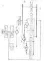
- the determination of the network or consumer period interval J or j as a function of the corresponding synchronization angle can be seen in particular from the flow chart.
- the method according to the invention is accessible to a tendon according to a further advantageous embodiment:
- the numbers X, Y or x, y are increased or decreased by the number N, the numbers x, y by n.
- n and N are positive integers between zero and essentially half of the number of network phases or consumer phases.
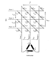
- Figure 1 shows the circuit of the direct converter for an M-phase network and an m-phase consumer.
- the current-carrying thyristor pair T X, y and T x, Y is clearly highlighted by means of black symbols.
- the ignition conditions of the individual thyristors can be determined as a function of the network or consumer synchronization angle PHI or phi.
- blocking times tau can also be introduced in the exemplary embodiments for the case of line-commutation, the upper time limit of the consumer period interval j being reduced by tau, with the result that the time period for the firing of thyristors is reduced.
- the consumer voltage can be controlled by shifting the network synchronization angle PHI with respect to the fundamental oscillation of the chained network voltage u I, II , by changing the control angle A in accordance with equation (2) above in conjunction with equation (1) above.
- the output voltage was reduced in accordance with the output frequency, since this relation is typical for the operation of electrical induction machines.
- the vertical, dashed lines and the four time axes crossing in Figures 3 and 4 indicate the ignition times of the corresponding thyristors, whereby the blocking time tau was taken into account to reduce the harmonic content of the currents.
- the voltage or current curves achieved at f F run according to. Figure 6.
- the proposed commutation method should preferably be applied to a polygonally connected consumer. In such a case, the currents run in the consumer windings of the delta connection according to. Figure 2 (i 1,2 , i2,3 and i3 , 1 ) roughly as shown in Figure 6 g e- .
- the thyristors to be fired always have a positive anode-cathode voltage if the load phase angle psi is less than 60 °, ie its cosine is greater than 0.5.
- the advantage achieved with this is there in particular in that for wide areas of electrical drive technology (e.g.
- the converter operated with the method according to the invention does not require a device for detecting the current direction, unlike in all previously known direct converters with natural commutation, which, for example, use HALL-Wand-1s for current direction detection.
Landscapes
- Engineering & Computer Science (AREA)
- Power Engineering (AREA)
- Ac-Ac Conversion (AREA)
- Control Of Direct Current Motors (AREA)
Abstract
Description
Die Erfindung betrifft ein Verfahren zur natürlichen, netz- oder verbrauchergeführten Kommutierung eines Direktumrichters, geschaltet zwischen einen M-phassigen Netz mit der Frequenz F und einem m-phasigen Verbraucher mit der Frequenz f, insbesondere einer elektrischen Maschine, wobei der Direktumrichter 2 · M · m Thyristoren umfaßt, die jede Netzphase mit jeder Verbraucherphase bidirektional verbinden.The invention relates to a method for natural, network or consumer-guided commutation of a direct converter, connected between an M-phase network with the frequency F and an m-phase consumer with the frequency f, in particular an electrical machine, the
Ein derartiger Umrichter ist beschrieben in G. Möltgen, "netzgeführte Stromricher mit Thyristoren " (Verlag Siemens AG, Berlin und München, dritte Auflage 1974, Kapitel 29, S. 291-299). Die Schaltung dort (Bild 225) umfaßt neben drei dreiphasigen Trenntransformatoren sechs vollgesteuerte Drehstromrichterbrücken mit insgesamt 36 Thyristoren. Für den Fall ohne Sternpunktleiter umfaßt die Schaltung dort (Bild 226) drei Trenntransformatoren mit drei im Dreieck gestaltete Drehstromrichterbrücken mit insgesamt 18 Thyristoren.Such a converter is described in G. Möltgen, "network-controlled current converter with thyristors" (Verlag Siemens AG, Berlin and Munich, third edition 1974, chapter 29, pp. 291-299). The circuit there (image 225) comprises in addition to three-phase isolation transformers six fully g esteuerte rotary converter bridges with a total of 36 thyristors. In the case Without a neutral point conductor, the circuit there (Figure 226) comprises three isolating transformers with three triangular-shaped converter bridges with a total of 18 thyristors.
In Bödefeld/Sequenz "Elektrische Maschinen" (Springerverlag 1981, S. 262, Abb. 3.74) ist ein Direktumrichter mit variabler Frequenz und Spannungsamplitude zum Betrieb einer dreiphasigen Synchronmaschine beschrieben. Jede der drei Maschinenwicklungen wird seperat von zwei antiparallel geschalteten, vollgesteuerten Drehstromrichterbrücken (Umkehrstromrichter) gespeist, wobei die Wicklungen untereinander keine galvanischen Verbindungen aufweisen. Zwischen Direktumrichter und Drehstromnetz sind ebenfalls dreiphasige Trenntransformatoren geschaltet.Bödefeld / Sequence "Electrical Machines" (Springerverlag 1981, p. 262, Fig. 3.74) describes a direct converter with variable frequency and voltage amplitude for operating a three-phase synchronous machine. Each of the three machine windings is fed separately from two fully-controlled three-phase converter bridges (reversing converter) connected in anti-parallel, the windings not having any galvanic connections to one another. Three-phase isolating transformers are also connected between the direct converter and the three-phase network.
Ähnliche Schaltungen werden in R. Jäger, "Leistungselektronik Grundlagen und Anwendungen" (VDE-Verlag 1977, S. 248-250) sowie in K.Bystorn "Leistungselektronik" (Band II, Hanser -Verlag München und Wien 1979, S. 310-313) beschrieben.Similar circuits are described in R. Jäger, "Power electronics basics and applications" (VDE Verlag 1977, pp. 248-250) and in K.Bystorn "Power electronics" (Volume II, Hanser Publishing House Munich and Vienna 1979, p. 310- 313).
Alle diese Schaltungen weisen den gravierenden Nachteil auf, daß im falle einer dreiphasigen Ausführung lediglich Ausgangsfrequenzen bis zu höchstens 40% der Eingangsfrequenz gefahren werden können. Bei einem Netz mit einer Frequenz von 50 Hz können mit solchen Umrichtern also maximal etwa 20 Hz erzeugt werden. Ferner sind in der Regel Trenntransformatoren zwischen Netz und Umrichter geschaltet, um interne Kurzschlüsse im Direktumrichter zu vermeiden. Allerdings stellen diese Trenntransformatoren einen erheblichen zusätzlichen Aufwand dar, zumal sie für die volle Leistung auszulegen sind.All these circuits have the serious disadvantage that in the case of a three-phase version, only output frequencies up to a maximum of 40% of the input frequency can be driven. In the case of a network with a frequency of 50 Hz, a maximum of approximately 20 Hz can be generated with such converters. In addition, isolating transformers are usually connected between the mains and the converter in order to avoid internal short circuits in the direct converter. However, these isolating transformers represent a considerable additional effort, especially since they have to be designed for full power.
Der Erfindung liegt die Aufgabe zugrunde, ein Verfahren zur natürlichen Kommutierung eines Direktumrichters der eingangs genannten Art zu schaffen, das eine kontinuierliche Änderung der Verbraucherfrequenz bzw. der Verbraucherspannung von Null bis zur Netzfrequenz bzw. bis zur Netzspannung ermöglicht. Der Direktumrichter soll dabei mit einer geringen Anzahl von Thyristoren ohne Verwendung weiterer, zwischen Netz und Umrichter und/oder zwischen Umrichter und Verbraucher zu schaltender Energieumformer (z.B. Trenntransformatoren) betreibbar sein.The invention has for its object to provide a method for natural commutation of a direct converter of the type mentioned that enables a continuous change in the consumer frequency or the consumer voltage from zero to the mains frequency or to the mains voltage. The direct converter should be able to be operated with a small number of thyristors without the use of further energy converters (e.g. isolating transformers) to be switched between the network and converter and / or between converter and consumer.
Diese Aufgabe wird erfindungsgemäß durch die im Anspruch 1 gekennzeichneten Merkmale gelöst.This object is achieved by the features characterized in
Demnach führen also - abgesehen von kommutierungsbedingten Überlappunsphasen- im wesentlichen immer nur zwei Thyristoren TX,y und Tx,Y gleichzeitig Strom. Mit TX,y bzw. Tx,Y sind diejenigen Thyristoren be- zeichnet, deren Anode mit der Netzphase X und deren Kathode mit der Verbraucherphase y bzw. deren Anode mit der Verbraucherphase x und deren Kathode mit der Netzphase Y galvanisch verbunden sind.Accordingly, apart from overlap phases caused by commutation, essentially only two thyristors T X, y and T x, Y conduct current at the same time. T X, y and T x, Y denote those thyristors whose anode is electrically connected to the line phase X and whose cathode is connected to the load phase y or whose anode is connected to the load phase x and whose cathode is connected to the line phase Y.
Für das erfindungsgemäße Kommutierungsverfahren ist ferner wesentlich, daß jede Netzperiode 1/F bzw. Verbraucherperiode 1/f jeweils in maximal 2· M bzw. 2. m Zeitintervalle J bzw. j unterteilt wird. Die Zeitintervalle J = 1... 2· M bzw. j = 1... 2. m sind dabei zur verketteten Spannung uI,II bzw. u1,2 des Netzes bzw. Verbrauchers synchronisiert. Dementsprechend werden im folgenden ein Netzsynchronisierungswinkel PHI bzw. ein Verbrauchersynchronisierungswinkel phi eingeführt.It is also essential for the commutation method according to the invention that each
Für den Netzsynchronisierungswinkels PHI gilt:
(1) PHI = 2 · pi · F · t = arc sin (uI,II/UI,II)+GAMMA mit pi = 3,14The following applies to the network synchronization angle PHI:
(1) PHI = 2 · pi · F · t = arc sin (u I, II / U I, II ) + GAMMA with pi = 3.14
Hierbei ist uI,II der Momentanwert der Grundschwingung der verketteten Netzspannung, UI,II die Amplitude der verketteten Netzspannung zwischen den Netzphasen I und II.Here u I, II is the instantaneous value of the fundamental oscillation of the chained network voltage, U I, II the amplitude of the chained network voltage between the network phases I and II.
Für GAMMA gilt:
(2) GAMMA = B + A,The following applies to GAMMA:
(2) GAMMA = B + A,
wobei mit B ein fester Netz-Versatzwinkel (rad.) gemeint ist, der zur einmaligen Synchronisation von PHI mit uI,II dient. A steht für den Steuerwinkel (rad.), der die Steuerung des Verhältnisses der Verbraucherspannungsamplitude zur Netzspannungsamplitude bzw. des Stromes und der Leistung bei Netzkommutierung ermöglicht.where B is a fixed mesh offset angle (rad.), which is used for the one-time synchronization of PHI with u I, II . A stands for the control angle (rad.), Which enables the control of the ratio of the consumer voltage amplitude to the mains voltage amplitude or the current and the power during mains commutation.
Analog gilt für den Verbraucher-Synschronisierungswinkel (rad.):
(3) phi = 2. pi f · t = arc sin (u1,2/U1,2)+gammaThe same applies analogously to the consumer synchronization angle (rad.):
(3) phi = 2. pi f · t = arc sin (u 1,2 / U 1,2 ) + gamma
Hierbei sind u1,2 der Momentanwert der Grundschwingung der verketteten Verbraucherspannung, und U1'2 die Amplitude der verketteten Verbraucherspannung zwischen den Verbraucherphasen 1 und 2.Here u 1,2 are the instantaneous value of the fundamental oscillation of the chained consumer voltage , and U 1'2 the amplitude of the chained consumer voltage between
Der Winkel gamma, der einen Verbraucher-Versatzwinkel (rad.) darstellt, ist wie folgt definiert:
(4) gamma = beta + alpha,The angle gamma, which represents a consumer offset angle (rad.), Is defined as follows:
(4) gamma = beta + alpha,
wobei beta der feste Verbraucherversatzwinkel (rad.) ist und zur einmaligen Synchronisation von phi mit u1,2 dient. Der Steuerwinkel alpha (rad.) dient zur Steuerung des Verhältnisses der Verbräücherspannungsamplitude zur Netzspannungsamplitude bzw. des Stromes und Leistung bei Verbraucherkommutierung.where beta is the fixed consumer offset angle (rad.) and is used for one-time synchronization of phi with u 1 , 2 . The control angle alpha (rad.) Is used to control the ratio of the consumer voltage amplitude to the mains voltage amplitude or the current and power for consumer commutation.
Während des Überlappungszeitraumes zwischen dem Netzperiodenintervall J und dem Verbraucherperiodenintervall j werden die beiden Thyristoren TX,y und Tx,Y zur Zündung freigegeben. Die Zündung selbst erfolgt jeweils zu Beginn des Überlappungszeitraumes.During the overlap period between the network period interval J and the consumer period interval j, the two thyristors T X , y and T x, Y are released for ignition. The ignition itself takes place at the beginning of the overlap period.
Die Ermittlung der Zahlen X,Y zur Auswahl der zu zündenden Thyristoren in Abhängigkeit vom Netz- synchronisierungswinkel PHI gem. Gleichung (1) kann insbesondere entsprechend dem nachstehenden als rekursiver Algorithmus dargestellten Prinzip erfolgen:
- Algorithmus in PASCAL-ähnlicher Notation:
- procedure netzsynchronisierte Kommutierung;
- const pi = 3.14;
- integer M,J, X,Y; comment Netzphasen, Zeitintervall, Bezeichnung für die Netzphasen;
- radiant PHI; comment Netzsynchronisierungswinkel;
- real F,t; comment Netzfrequenz, Echtzeit;
- begin
- M:=Anzahl der Netzphasen;
- F:=Netzfrequena;
- J:=1;
- while J=J do comment Endlosschleife;
- begin
- X:=trunc (0,5(J+1));
- if not odd(M)
- then if J<= (M+1 ) then Y: = trunc (0,5(M+J))
- else Y: = trunc (0,5(M+J)-M)
- else if J<= M then Y: = trunc (0,5(M+J+1)
- else Y: = trunc (0,5(M+J+1)-M);
- comment Warteschleife bis zum nächsten Intervall;
- repeat
- begin t: = echtzeituhr; PHI:= 2· pi F· t end until PHI>J· pi/M;
- J:= J+1;
- if PHI> = 2· pi then reset echtzeituhr;
- end
- end procedure.
- Algorithm in PASCAL-like notation:
- procedure network-synchronized commutation;
- const pi = 3.14;
- integer M, J, X, Y; comment grid phases, time interval, designation for the grid phases;
- radiant PHI; comment network synchronization angle;
- real F, t; comment network frequency, real time;
- begin
- M: = number of network phases;
- F: = network frequency;
- J: = 1;
- while J = J do comment loop;
- begin
- X: = trunc (0.5 (J + 1));
- if not odd (M)
- then if J <= (M + 1) then Y: = trunc (0.5 (M + J))
- else Y: = trunc (0.5 (M + J) -M)
- else if J <= M then Y: = trunc (0.5 (M + J + 1)
- else Y: = trunc (0.5 (M + J + 1) -M);
- comment Waiting until the next interval;
- repeat
- begin t: = real time clock; PHI: = 2 · pi F · t end until PHI> J · pi / M;
- J: = J + 1;
- if PHI> = 2 · pi then reset real time clock;
- end
- end procedure.
Mit der darin verwendeten Funktion v = trunc (w) wird jeder rationalen Zahl bzw. jedem Dezimalbruch w größer als Null die größte ganze Zahl v, die kleiner oder gleich w ist, zugeordnet (vgl. Jensen /Wirth "PASCAL User Manual and Report", 2nd edition, 1978, Seite 13).With the function v = trunc (w) used therein, each rational number or every decimal fraction w greater than zero is assigned the largest integer v that is less than or equal to w (cf. Jensen / Wirth "PASCAL User Manual and Report" , 2nd edition, 1978, page 13).
Der obige Algorithmus, der zur prinzipiellen Verdeutlichung eines erfindungsgemäßen Merkmals, nicht aber als ablauffähiges Rechenprogramm dienen soll, ermöglicht die Ermittlung der Netzphasen X bzw. Y, die mit den entsprechenden Verbraucherphasen y bzw. x über dazwischengeschaltete Thyristoren zu verbinden sind.The above algorithm, which is intended to illustrate the principle of a feature according to the invention, but not as an executable computer program, enables the determination of the network phases X and Y, which are to be connected to the corresponding consumer phases y and x via interposed thyristors.
Die Verbraucherphasen y bzw. x können analog in Abhängigkeit vom Verbrauchersynchronisierungswinke1 phi gem. Gleichung (3) ermittelt werden, indem im obigen Algorithmus y anstelle von X bzw. x anstelle von Y eingesetzt wird. Ferner sind m, j, f bzw. phi anstelle von M, J, F bzw. PHI einzusetzen.The consumer phases y and x can be analogous depending on the
Das erfindungsgemäße Kommutierungsverfahren kann also z.B. mittels zweier, unabhängig voneinander ablaufender Rechnerprogramme oder mittels zweier nahezu identischer Rechenschaltungen realisiert werden, die nach weitgehend gleicher algorithmischer Struktur jeweils die netzsynchronisierte und die verbrauchersynchronisierte Kommutierung berechnen.The commutation method according to the invention can thus e.g. can be implemented by means of two computer programs running independently of one another or by means of two almost identical computer circuits which, based on largely the same algorithmic structure, calculate the network-synchronized and the consumer-synchronized commutation.
Natürlich sind auch Abwandlungen des obigen Algorithmus zur Berechnung der Zahlen X,Y,x,y für die Zündung des Thyristorpaars Tx,y, Tx,Y'denkbar, die dennoch im Rahmen des allgemeinen Erfindungsprinzips liegen, sofern die Ermittlung des Thyristorpaars in Abhängigkeit vom genannten Netz- bzw. Verbrauchersynchronisierungswinkel erfolgt, und die Freigabe zur Ansteuerung der beiden Thyristoren im Überlappungszeitraum der genannten Netz- bzw. Verbrauchersynchronisierungsintervalle bewirkt wird. So ist im beiliegenden Bild 1 eine gegenüber dem obigen PASCAL-Algorithmus abgewandelte Ablauflogik in Form eines Flußdiagramms dargestellt, nach deren Prinzip die Zahlen X,Y ebenfalls erfindungsgemäß berechnet werden können. Zur Berechnung der Zahlen x, y für die Verbraucherphasen sind, wie oben beim PASCAL-ähnlich notierten Algorithmus, die mit Kleinbuchstaben bezeichneten Größen anstelle der mit Großbuchstaben bezeichneten einzusetzen. Aus dem flußdiagramm ist insbesondere die Bestimmung des Netz- bzw. Verbraucherperiodenintervalls J bzw. j in Abhängigkeit vom entsprechenden Synchronisierungswinkel erkennbar.Of course, modifications of the above algorithm for calculating the numbers X, Y, x, y for the ignition of the thyristor pair T x, y , T x, Y 'are also conceivable, but are within the general principle of the invention, provided that the thyristor pair is determined in Dependence on the mentioned network or consumer synchronization angle takes place, and the release for controlling the two thyristors is effected in the overlap period of the above network or consumer synchronization intervals. In the attached
Zur Verringerung des Oberwellengehaltes der Ströme werden die Zeitintervalle j entsprechend dem Verbraucher-Synchronisierungswinkels phi bzw. J entsprechend dem Netz-Synchronisierungswinkels PHI jeweils mit einer Sperrzeit TAU bzw. tau versehen, während der keine Thyristoren gezündet werden. Die Sperrzeit tau für das Verbraucherperiodeninterval j ergibt sich aus
- (5) tau = 1/4·M·F.
- (6) TAU = 1/4. m· f.
- (7) delta = pi ·f/2· M· F
- (5) tau = 1 / 4MF.
- (6) TAU = 1/4. m · f.
- (7) delta = pi · f / 2 · M · F
Für den Sperrwinkel DELTA bei Verbraucherkommutierung gilt dann:
- (8) DELTA = pi . F/2 ·m · f,
- (8) DELTA = pi. F / 2mf,
Um beispielsweise in einer als Verbraucher betriebenen elektrischen Mschine die induzierte Spannung (elektromotorische Kraft - EMK) zwecks Feldschwächung reduzieren zu können, ist gemäß einer weiteren vorteilhaften Ausgestaltung das erfindungsgemäße Verfahren einer Sehnung zugänglich: Bei der Ermittlung der Zahlen X,Y bzw. x, y werden die Zahlen X bzw. Y um die Zah1 N, die Zahlen x, y um n vergrößert oder verkleinert. Dabei sind n bzw. N positive ganze Zahlen zwischen null und im wesentlichen der Hälfte der Anzahl der Netzphasen bzw. Verbraucherphasen.In order to be able to reduce the induced voltage (electromotive force - EMF) for the purpose of weakening the field, for example, in an electrical machine operated as a consumer, the method according to the invention is accessible to a tendon according to a further advantageous embodiment: When determining the numbers X, Y or x, y the numbers X and Y are increased or decreased by the number N, the numbers x, y by n. Here, n and N are positive integers between zero and essentially half of the number of network phases or consumer phases.
Betreibt man einen m-phasigen Verbraucher wie z.B. eine elektrische Maschine so, als hätte sie weniger als m Phasen, so läßt sich dadurch deren Drehzahl erhöhen. Durch Halbierung, Drittelung usw. der Phasenzahl m der Verbrauchermaschine läßt sich deren Synchrondrehzahl verdoppeln, verdreifachen usw. Dem dient eine weitere Ausgestaltung des erfindungsgemäßen Verfahrens, wonach dem Verfahrensalgorithmus anstelle der tatsächlichen Netz- bzw. Verbraucherphasenzahl M bzw. m demgegenüber vorzugsweise halbierte, gedrittelte usw. Phasenzahlen M' bzw. m' vorgegeben werden.If you operate an m-phase consumer such as an electrical machine as if it had fewer than m phases, its speed can be increased. By halving, thirding, etc. the number of phases m of the consumer machine, its synchronous speed can be doubled, tripled, etc. This serves a further embodiment of the method according to the invention, according to which the method algorithm instead of the actual network or consumer phase number M or m, in contrast, preferably halved, divided into thirds, etc. Phase numbers M 'or m' can be specified.
Bezüglich weiterer Ausbildungen und Verbesserungen des erfindungsgemäßen Verfahrens wird auf die Unteransprüche und auf die nachfolgende Erläuterung der Erfindung an Hand der Zeichnung verwiesen. Es zeigen
Bild 1 ein Flußdiagramm für eine Ablauflogik zur Durchführung des erfindungsgemäßen Verfahrens;Bild 2 einen Direktumrichter mit natürlicher Kommutierung für ein M-phasiges Netz und einen m-phasigen Verbraucher zur Durchführung des erfindungsgemäßen Verfahrens;Bild 3 einen Direktumrichter mit natürlicher Kommutierung zur Durchführung des erfindungsgemäßen Verfahrens für ein dreiphasiges Netz und einen dreiphasigen Verbraucher;- Bild 4 die graphisch ermittelten Spannungsverläufe u1,2' u2,3' und u3,1 bei f = 0,26 F und M=m=3;
- Bild 5 graphisch ermittelte Spannungsverläufe u1,2' u2,3 und u3,1 bei f = 0,71 F und M=m=3;
- Bild 6 graphisch ermittelte Spannungsverläufe u 1,2' u2,3 und u3,1 bei f = F und M=m=3;
- Bild 7 Strom- und Spannungsverläufe bei f = F.
- Figure 1 is a flowchart for a flow logic for performing the method according to the invention;
- Figure 2 shows a direct converter with natural commutation for an M-phase network and an m-phase consumer for implementing the method according to the invention;
- 3 shows a direct converter with natural commutation for carrying out the method according to the invention for a three-phase network and a three-phase consumer;
- Figure 4 shows the graphically determined voltage curves u 1 , 2 ' u 2 , 3' and u 3 , 1 at f = 0.26 F and M = m = 3;
- Figure 5 graphically determined voltage curves u 1,2 'u 2 , 3 and u 3 , 1 at f = 0.71 F and M = m = 3;
- Figure 6 graphically determined voltage curves u 1,2 ' u 2,3 and u 3 , 1 with f = F and M = m = 3;
- Figure 7 Current and voltage profiles at f = F.
In Bild 1 ist die Schaltung des Direktumrichters für ein M-phasiges Netz und einen m-phasigen Verbraucher dargestellt. Das gleichzeitig stromführende Thyristorpaar TX,y und Tx,Y ist mittels schwarz ausgefüllter Schaltsymbole deutlich hervorgehoben. In Bild 2 ist ein Ausführungsbeispiel mit einem dreiphasigen Netz (M = 3) und einem dreiphasigen Verbraucher (m = 3) bei Netzkommutierung gezeigt. Die dazugehörige Schaltung des Direktumrichters umfaßt die 2 · M · m = 2· 3 · 3 = 18 Thyristoren.Figure 1 shows the circuit of the direct converter for an M-phase network and an m-phase consumer. The current-carrying thyristor pair T X, y and T x, Y is clearly highlighted by means of black symbols. Figure 2 shows an embodiment with a three-phase network (M = 3) and a three-phase load (m = 3) with network commutation. The associated circuit of the direct converter comprises the 2 · M · m = 2 · 3 · 3 = 18 thyristors.
Mit Hilfe des oben angegebenen Verfahrensalgorithmus lassen sich hierfür die Zündbedingungen der einzelnen Thyristoren in Abhängigkeit vom Netz- bzw. Verbraucher-Synchronisierungswinkel PHI bzw. phi ermitteln.With the aid of the above-mentioned method algorithm, the ignition conditions of the individual thyristors can be determined as a function of the network or consumer synchronization angle PHI or phi.
Ferner können in den Ausführungsbeispielen noch Sperrzeiten tau für den Fall netzgeführter Kommutierung eingeführt sein, wobei die obere zeitliche Grenze des Verbraucherperiodenintervalls j um tau vermindert ist mit der Folge, daß die Zeitspanne für die Zündung von Thyristoren verringert ist.Furthermore, blocking times tau can also be introduced in the exemplary embodiments for the case of line-commutation, the upper time limit of the consumer period interval j being reduced by tau, with the result that the time period for the firing of thyristors is reduced.
Die Steuerung der Verbraucherspannung kann dadurch erfolgen, daß der Netz-Synchronisierungswinkel PHI gegenüber der Grundschwingung der verketteten Netzspannung uI,II verschoben wird, indem der Steuerwinkel A gemäß obiger.Gleichung (2) in Verbindung mit obiger Gleichung (1) verändert wird.The consumer voltage can be controlled by shifting the network synchronization angle PHI with respect to the fundamental oscillation of the chained network voltage u I, II , by changing the control angle A in accordance with equation (2) above in conjunction with equation (1) above.
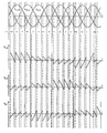
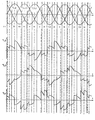
In den Bildern 3, 4 und 5 sind die entsprechend dem erfindungsgemäßen Verfahren graphisch ermittelten Spannungsverläufe u 1,2, u 2,3 und u3,1 jeweils für f = 0,26 F, f = 0,71 F und f = f dargestellt. Die Netzfrequenz kann dabei z.B. F = 50 Hz betragen. Die Ausgangsspannung wurde entsprechend der Ausgangsfrequenz abgesenkt, da diese Relation für den Betrieb elektrischer Drehfeldfmaschinen typisch ist.In Figures 3, 4 and 5, the voltage curves u 1,2 , u 2 , 3 and u 3,1 determined graphically in accordance with the method according to the invention are each for f = 0.26 F, f = 0.71 F and f = f. The mains frequency can be, for example, F = 50 Hz. The output voltage was reduced in accordance with the output frequency, since this relation is typical for the operation of electrical induction machines.
Die senkrechten, durchgezogenen und die vier waagrechten Zeitachsen kreuzenden Linien in den Bildern 3 - 5 begrenzen beidseitig je ein Zeitintervall J, das bei 2 · M = 2. 3 = 6 Zeitintervallen pro Netzschwingungsperiode 60° entspricht. Die senkrechten, gestrichelten und die vier Zeitachsen kreuzenden Linien in den Bildern 3 und 4 geben die Zündzeitpunkte der entsprechenden Thyristoren an, wobei zur Verringerung des Oberwellengehalts der Ströme die genannte Sperrzeit tau berücksichtigt wurde.The vertical, solid lines and the four horizontal time axes crossing in Figures 3 - 5 each delimit a time interval J on both sides, which corresponds to 60 ° at 2 · M = 2. 3 = 6 time intervals per network oscillation period. The vertical, dashed lines and the four time axes crossing in Figures 3 and 4 indicate the ignition times of the corresponding thyristors, whereby the blocking time tau was taken into account to reduce the harmonic content of the currents.
Die bei f = F erzielten Spannungs- bzw. Stromverläufe verlaufen bei induktiver Last gem. Bild 6. Das vorgeschlagene Kommutierungsverfahren ist vorzugsweise auf einen polygonal verschalteten Verbraucher anzuwenden. Solchenfalls verlaufen die Ströme in den Verbraucherwicklungen der Dreieckschaltung gem. Bild 2 (i1,2, i2,3 und i3 , 1) ungefähr wie in Bild 6 ge- zeigt. Ferner finden gem. Ausführungsbeispiel nach Bild 6 die zu zündenden Thyristoren immer eine positive Anoden-Kathodenspannung vor, wenn der Lastphasenwinkel psi kleiner als 60°, d.h. dessen Kosinus größer als 0,5 ist. Der damit erzielte Vorteil besteht insbesondere darin, daß für weite Bereiche der elektrischen Antriebstechnik (z.B. Drehzahlsteuerungen von Pumpen oder Ventilatoren, die von Asynchron-Kurzschlußläufer-Motoren angetrieben werden) der mit dem erfindungsgemäßen Verfahren betriebene Umrichter keine Einrichtung zur Stromrichtungs-Erfassung benötigt, anders als bei allen bisher bekannten Direktumrichtern mit natürlicher Kommutierung, die zur Stromrichtungserfassung beispielsweise HALL-Wand-1er verwenden.The voltage or current curves achieved at f = F run according to. Figure 6. The proposed commutation method should preferably be applied to a polygonally connected consumer. In such a case, the currents run in the consumer windings of the delta connection according to. Figure 2 (i 1,2 , i2,3 and i3 , 1 ) roughly as shown in Figure 6 g e- . Furthermore, according to Exemplary embodiment according to Figure 6, the thyristors to be fired always have a positive anode-cathode voltage if the load phase angle psi is less than 60 °, ie its cosine is greater than 0.5. The advantage achieved with this is there in particular in that for wide areas of electrical drive technology (e.g. speed controls of pumps or fans which are driven by asynchronous squirrel-cage motors) the converter operated with the method according to the invention does not require a device for detecting the current direction, unlike in all previously known direct converters with natural commutation, which, for example, use HALL-Wand-1s for current direction detection.
Ein weiterer Vorteil der vorgeschlagenen Lösung besteht in der steuerungstechnisch einfach zu realisierenden Möglichkeit, nach Erreichen der Netzfrequenz (f = F) und der Netzspannung (U1,2 = U I,II)) den Verbraucher mittels eines Schützes direkt ans Netz zu schalten und dadurch den Direktumrichter zu überbrücken, da gem. Bild 5 bereits eine Synchronisation zwischen Netz- und Verbraucherspannung vorhanden ist.Another advantage of the proposed solution is the possibility to implement the control technology in a simple manner, after reaching the mains frequency ( f = F) and the mains voltage (U 1,2 = U I, II) ) the consumer is connected directly to the mains by means of a contactor and thereby bridging the direct converter, since acc. Figure 5 there is already a synchronization between the mains and consumer voltage.
Claims (6)
dadurch gekennzeichnet,
daß die Netzperioden 1/F bzw. Verbraucherperioden 1/f synchron zur verketteten Spannung zwischen den ersten beiden Phasen des Netzes bzw. Verbrauchers in 2. M bzw. 2. m jeweils gleich lange, zeitliche Intervalle J bzw. j unterteilt werden, wobei J bzw. j ganze Zahlen zwischen eins und
2. M bzw. 2. m sind, und
daß in der Überlappungsphase zweier Intervalle J und j ein Thyristorpaar TX,y und Tx,Y, das gleichzeitig Strom von einer Netzphase X zu einer Verbraucherphase y und von einer Verbraucherphase x zu einer Netzphase Y führen kann, zur Zündung freigegeben wird, wobei X = trunc (0,5(J+1)), y = trunc (0,5(j+1)) gilt, und, falls m bzw. M geradzahlig sind,
characterized,
that the network periods 1 / F or consumer periods 1 / f synchronously to the chained voltage between the first two phases of the network or consumer in 2. M or 2. m each time intervals J or j are divided into the same length, J or j integers between one and
2. M and 2. m are, and
that in the overlapping phase of two intervals J and j a thyristor pair T X, y and T x, Y , which can simultaneously lead current from a network phase X to a consumer phase y and from a consumer phase x to a network phase Y, is released for ignition, where X = trunc (0.5 (J + 1)), y = trunc (0.5 (j + 1)), and, if m and M are even numbers,
dadurch gekennzeichnet,
daß im Falle netzgeführter Kommutierung jedes Verbraucherperiodenintervall j eine Sperrzeit tau = 1/4· M· F aufweist, während der die Zündung der Thyristoren gesperrt ist.2. The method according to claim 1,
characterized,
that in the case of line-commutation every consumer period interval j has a blocking time tau = 1/4 · M · F, during which the ignition of the thyristors is blocked.
dadurch gekennzeichnet,
daß im Falle verbrauchergeführter Kommutierung jedes Netzperiodenintervall J eine Sperrzeit TAU = 1/4· m · f aufweist, während der die Zündung der Thyristoren gesperrt ist.3. The method according to claim 1,
characterized,
that in the case of consumer-guided commutation, each grid period interval J has a blocking time TAU = 1/4 · m · f during which the ignition of the thyristors is blocked.
daß bei der Ermittlung der Zahlen X,Y bzw. x,y die Zahlen x bzw. y um n und/oder die Zahlen X bzw. Y um N vergrößert oder verkleinert werden, wobei n und N positive, ganze Zahlen im wesentlichen zwischen null und 0,5m bzw. 0,5M bei geradzahligem m bzw. M und zwischen null und 0,5(m+1) bzw. 0,5(M+1) bei ungeradzahligem m bzw. M sind.5. The method according to any one of claims 1-4, characterized in
that when determining the numbers X, Y and x, y the numbers x and y are increased or decreased by n and / or the numbers X and Y by N, where n and N are positive, integers essentially between zero and 0.5m and 0.5M for even-numbered m and M, and between zero and 0.5 (m + 1) and 0.5 (M + 1) for odd-numbered m and M, respectively.
Priority Applications (1)
| Application Number | Priority Date | Filing Date | Title |
|---|---|---|---|
| AT86100961T ATE68642T1 (en) | 1985-01-24 | 1986-01-24 | PROCESSES FOR NATURAL, LINE OR CONSUMPTION COMMUTATION. |
Applications Claiming Priority (2)
| Application Number | Priority Date | Filing Date | Title |
|---|---|---|---|
| DE3502204 | 1985-01-24 | ||
| DE19853502204 DE3502204A1 (en) | 1985-01-24 | 1985-01-24 | DIRECT INVERTER WITH NATURAL COMMUTATION |
Publications (3)
| Publication Number | Publication Date |
|---|---|
| EP0189211A2 true EP0189211A2 (en) | 1986-07-30 |
| EP0189211A3 EP0189211A3 (en) | 1987-10-14 |
| EP0189211B1 EP0189211B1 (en) | 1991-10-16 |
Family
ID=6260571
Family Applications (1)
| Application Number | Title | Priority Date | Filing Date |
|---|---|---|---|
| EP86100961A Expired - Lifetime EP0189211B1 (en) | 1985-01-24 | 1986-01-24 | Method for natural commutation piloted by the network or load |
Country Status (3)
| Country | Link |
|---|---|
| EP (1) | EP0189211B1 (en) |
| AT (1) | ATE68642T1 (en) |
| DE (2) | DE3502204A1 (en) |
Families Citing this family (3)
| Publication number | Priority date | Publication date | Assignee | Title |
|---|---|---|---|---|
| DE3913675C1 (en) * | 1989-04-26 | 1990-01-11 | Georg Dipl.-Ing. 8000 Muenchen De Hienz | Commutating arrangement, for frequency converter - has thyristors galvanically connected in pairs and antiparallel to each mains and consumer phase |
| DE19746797B4 (en) * | 1997-10-23 | 2012-05-24 | Siemens Ag | Method for controlling bidirectional switches in power converters |
| DE10051222A1 (en) * | 2000-10-16 | 2002-04-25 | Alstom Switzerland Ltd | Method for operating a matrix converter and matrix converter for performing the method |
Citations (2)
| Publication number | Priority date | Publication date | Assignee | Title |
|---|---|---|---|---|
| DE2030107A1 (en) * | 1969-06-20 | 1970-12-23 | ||
| EP0124302A2 (en) * | 1983-04-06 | 1984-11-07 | Texas Instruments Incorporated | A.C. supply converter |
-
1985
- 1985-01-24 DE DE19853502204 patent/DE3502204A1/en active Granted
-
1986
- 1986-01-24 DE DE8686100961T patent/DE3681926D1/en not_active Expired - Lifetime
- 1986-01-24 AT AT86100961T patent/ATE68642T1/en not_active IP Right Cessation
- 1986-01-24 EP EP86100961A patent/EP0189211B1/en not_active Expired - Lifetime
Patent Citations (2)
| Publication number | Priority date | Publication date | Assignee | Title |
|---|---|---|---|---|
| DE2030107A1 (en) * | 1969-06-20 | 1970-12-23 | ||
| EP0124302A2 (en) * | 1983-04-06 | 1984-11-07 | Texas Instruments Incorporated | A.C. supply converter |
Non-Patent Citations (1)
| Title |
|---|
| Lappe: Thyristor-Stromrichter für Antriebsregelungen, VEB-Verlag * |
Also Published As
| Publication number | Publication date |
|---|---|
| DE3502204A1 (en) | 1986-08-14 |
| EP0189211B1 (en) | 1991-10-16 |
| ATE68642T1 (en) | 1991-11-15 |
| EP0189211A3 (en) | 1987-10-14 |
| DE3502204C2 (en) | 1988-02-25 |
| DE3681926D1 (en) | 1991-11-21 |
Similar Documents
| Publication | Publication Date | Title |
|---|---|---|
| DE2151589C2 (en) | Arrangement for controlling the speed of a three-phase three-phase motor | |
| EP0334112B1 (en) | Pulse converter driven induction machine | |
| EP1336241B1 (en) | Method for controlling a matrix converter | |
| WO2016155837A1 (en) | Converter arrangement and method for short-circuit protection thereof | |
| WO2006000111A1 (en) | Low harmonic multiphase converter circuit | |
| DE2225609C2 (en) | Arrangement for controlling the speed of a multiphase alternating current asynchronous motor fed via a static converter with variable voltage and, for example, with proportional frequency | |
| DE2239797A1 (en) | PROTECTIVE DEVICE TO PREVENT OVERVOLTAGE AND UNDERVOLTAGE CONDITIONS IN POWER CIRCUITS | |
| DE2224830A1 (en) | Versatile power converter with a high frequency connection | |
| DE2106310A1 (en) | Multiphase power converter circuit | |
| DE102011082365A1 (en) | Superconducting machine and method for its operation | |
| EP0373381B1 (en) | Three-phase inverter control process | |
| EP0189211B1 (en) | Method for natural commutation piloted by the network or load | |
| DE2030107A1 (en) | ||
| DE60132418T2 (en) | Method and system for zero-current signal detection in a line-commutated converter | |
| EP3531547B1 (en) | Operating circuit for coupling of a synchronous machine with a voltage network and method for the operation of same | |
| DE2050787C3 (en) | Bridge inverter with direct current commutation | |
| DE2653871A1 (en) | VOLTAGE GENERATOR | |
| DE2909686C2 (en) | ||
| DE2931878C2 (en) | Circuit arrangement for speed control of a three-phase asynchronous motor | |
| DE2339809C3 (en) | Arrangement for controlling the speed of a thyristor controlled three-phase synchronous motor | |
| DE2445540C3 (en) | Arrangement for controlling the speed of an asynchronous motor | |
| AT376531B (en) | SELF-GUIDED MULTI-PULSE RECTIFIER | |
| AT349578B (en) | CONTROL CIRCUIT FOR A SPEED ADJUSTABLE, COMMUTATORLESS INDUCTION MOTOR | |
| DE1268264B (en) | Speed-controlled converter machine | |
| WO2024083387A1 (en) | Operation of switching elements of an inverter |
Legal Events
| Date | Code | Title | Description |
|---|---|---|---|
| PUAI | Public reference made under article 153(3) epc to a published international application that has entered the european phase |
Free format text: ORIGINAL CODE: 0009012 |
|
| AK | Designated contracting states |
Kind code of ref document: A2 Designated state(s): AT CH DE FR GB LI |
|
| PUAL | Search report despatched |
Free format text: ORIGINAL CODE: 0009013 |
|
| AK | Designated contracting states |
Kind code of ref document: A3 Designated state(s): AT CH DE FR GB LI |
|
| 17P | Request for examination filed |
Effective date: 19871210 |
|
| 17Q | First examination report despatched |
Effective date: 19900314 |
|
| GRAA | (expected) grant |
Free format text: ORIGINAL CODE: 0009210 |
|
| AK | Designated contracting states |
Kind code of ref document: B1 Designated state(s): AT CH DE FR GB LI |
|
| PG25 | Lapsed in a contracting state [announced via postgrant information from national office to epo] |
Ref country code: GB Effective date: 19911016 |
|
| REF | Corresponds to: |
Ref document number: 68642 Country of ref document: AT Date of ref document: 19911115 Kind code of ref document: T |
|
| REF | Corresponds to: |
Ref document number: 3681926 Country of ref document: DE Date of ref document: 19911121 |
|
| PG25 | Lapsed in a contracting state [announced via postgrant information from national office to epo] |
Ref country code: AT Effective date: 19920124 |
|
| PG25 | Lapsed in a contracting state [announced via postgrant information from national office to epo] |
Ref country code: LI Effective date: 19920131 Ref country code: CH Effective date: 19920131 |
|
| EN | Fr: translation not filed | ||
| PG25 | Lapsed in a contracting state [announced via postgrant information from national office to epo] |
Ref country code: FR Effective date: 19920306 |
|
| GBV | Gb: ep patent (uk) treated as always having been void in accordance with gb section 77(7)/1977 [no translation filed] | ||
| PLBE | No opposition filed within time limit |
Free format text: ORIGINAL CODE: 0009261 |
|
| STAA | Information on the status of an ep patent application or granted ep patent |
Free format text: STATUS: NO OPPOSITION FILED WITHIN TIME LIMIT |
|
| REG | Reference to a national code |
Ref country code: CH Ref legal event code: PL |
|
| PG25 | Lapsed in a contracting state [announced via postgrant information from national office to epo] |
Ref country code: DE Effective date: 19921001 |
|
| 26N | No opposition filed | ||
| REG | Reference to a national code |
Ref country code: FR Ref legal event code: ST |