EP0189179B1 - Test adapter - Google Patents
Test adapter Download PDFInfo
- Publication number
- EP0189179B1 EP0189179B1 EP86100780A EP86100780A EP0189179B1 EP 0189179 B1 EP0189179 B1 EP 0189179B1 EP 86100780 A EP86100780 A EP 86100780A EP 86100780 A EP86100780 A EP 86100780A EP 0189179 B1 EP0189179 B1 EP 0189179B1
- Authority
- EP
- European Patent Office
- Prior art keywords
- contact pins
- combined plate
- contact
- plate
- front combined
- Prior art date
- Legal status (The legal status is an assumption and is not a legal conclusion. Google has not performed a legal analysis and makes no representation as to the accuracy of the status listed.)
- Expired - Lifetime
Links
Images
Classifications
-
- G—PHYSICS
- G01—MEASURING; TESTING
- G01R—MEASURING ELECTRIC VARIABLES; MEASURING MAGNETIC VARIABLES
- G01R1/00—Details of instruments or arrangements of the types included in groups G01R5/00 - G01R13/00 and G01R31/00
- G01R1/02—General constructional details
- G01R1/06—Measuring leads; Measuring probes
- G01R1/067—Measuring probes
- G01R1/073—Multiple probes
- G01R1/07307—Multiple probes with individual probe elements, e.g. needles, cantilever beams or bump contacts, fixed in relation to each other, e.g. bed of nails fixture or probe card
- G01R1/07314—Multiple probes with individual probe elements, e.g. needles, cantilever beams or bump contacts, fixed in relation to each other, e.g. bed of nails fixture or probe card the body of the probe being perpendicular to test object, e.g. bed of nails or probe with bump contacts on a rigid support
Abstract
Description
Die Erfindung betrifft einen Prüfadapter gemäß dem Oberbegriff des Anspruches 1.The invention relates to a test adapter according to the preamble of claim 1.
Derartige Prüfadapter dienen in Verbindung mit einem an ihre Kontaktstifte angeschlossenen Auswerter dem elektrischen Prüfen von elektrischen, insbesondere elektronischen Prüflingen, wie elektrischen und elektronischen Bauteilen, Schaltungen, Schaltkreisen, Leiterplatten, integrierten Schaltungen, festen Verdrahtungen oder dergl., auf elektrische Fehlerfreiheit.Test adapters of this type are used in conjunction with an evaluator connected to their contact pins for the electrical testing of electrical, in particular electronic test objects, such as electrical and electronic components, circuits, circuits, printed circuit boards, integrated circuits, fixed wiring or the like, for freedom from electrical faults.
Bei einer einzelnen Prüfung dienen alle oder ausgewählte Kontaktstifte des Prüfadapters dem elektrischen Kontaktieren von Prüfstellen des Prüflinges. Der Kontaktstift bildet in seiner Gesamtheit einen "elektrischen Leiter" zum Leiten eines Prüfstromes bzw. einer Prüfspannung bei jeder Prüfung einer von ihm kontaktierten Prüfstelle eines Prüflinges.In the case of a single test, all or selected contact pins of the test adapter serve to make electrical contact with test points of the test object. In its entirety, the contact pin forms an “electrical conductor” for conducting a test current or a test voltage each time a test point of a test object is contacted by it.
Derartige Prüfadapter haben im allgemeinen eine sehr große Anzahl von Kontaktstiften, um eine große Anzahl von Prüfstellen eines Prüflinges gleichzeitig kontaktieren zu können. Oft wird, insbesondere bei sogenannten Universaladaptern, jeweils auch nur eine mehr oder weniger große Teilanzahl der im Prüfadapter befindlichen Kontaktstifte für die Prüfung von Prüfstellen des jeweiligen Prüflinges eingesetzt, indem nur sie an den Auswerter angeschlossen oder nur die von ihnen geleiteten Prüfströme bzw. -spannungen im Auswerter ausgewertet werden. Dabei handelt es sich jedoch stets auch um relativ große Anzahlen von Kontaktstiften, die an der Prüfung eines Prüflinges als "elektrische Leiter" mitwirken.Such test adapters generally have a very large number of contact pins in order to be able to contact a large number of test points of a test object at the same time. Often, especially in the case of so-called universal adapters, only a more or less large number of the contact pins in the test adapter are used for testing test points of the respective test object by only connecting them to the evaluator or only the test currents or voltages they conduct be evaluated in the evaluator. However, these are always also relatively large numbers of contact pins which act as "electrical conductors" when testing a test object.
Infolge der zunehmenden Miniaturisierung bzw. zunehmender Funktionsvergrößerung von durch solche Prüfadapter zu prüfenden Prüflingen werden solche Prüfadapter mit immer mehr Kontaktstiften bestückt bzw. werden die Mittenabstände zwischen benachbarten Kontaktstiften oder das Rastermaß, falls die Kontaktstifte gemäß einem Raster gesteckt sind, immer kleiner.As a result of the increasing miniaturization or increasing function increase of test objects to be tested by such test adapters, such test adapters are equipped with more and more contact pins or the center distances between adjacent contact pins or the grid size, if the contact pins are plugged in according to a grid, are becoming ever smaller.
Es gibt heute schon Prüfadapter, die mit mehr als 100 000 Kontaktstiften bestückt werden. Jeder Kontaktstift muß im Prüfadapter so gehalten sein, daß dieser sowohl alle vom Kontaktstift ausgeübten Kräfte als auch die vom Prüfling auf die Kontaktspitze des einzelnen Kontaktstiftes ausgeübte axiale Kontaktkraft aufnehmen kann. Bei großen Anzahlen von Kontaktstiften muß dann der Prüfadapter ohne Verlust an Prüfgenauigkeit sehr große Kräfte aushalten können. So kann die Kontaktkraft eines einzelnen Kontaktstiftes, mit der er an eine Prüfstelle eines Prüflinges angedrückt wird, im allgemeinen 0,3 bis 3N betragen. Auch das Eigengewicht der Kontaktstifte ist zu beachten. So können z.B. 100 000 Kontaktstifte zusammen beispielsweise 50 bis 100 kg wiegen. Die auf eine so große Anzahl von Kontaktstiften beim Prüfen eines Prüflinges ausgeübten axialen Kräfte können dabei bspw. 3 bis 30 t betragen. Die Außendurchmesser der Gehäuse der Kontaktstifte sind ferner wegen des notwendigen geringen Mittenabstandes zwischen benachbarten Kontaktstiften in ihrem Durchmesser sehr klein und liegen meist etwa zwischen 0,2 und 1,4 mm, besonders zweckmäßig etwa zwischen 0,4 und 0,8 mm.There are already test adapters that are equipped with more than 100,000 contact pins. Each contact pin must be held in the test adapter in such a way that it can absorb all the forces exerted by the contact pin as well as the axial contact force exerted by the test specimen on the contact tip of the individual contact pin. With large numbers of contact pins, the test adapter must be able to withstand very large forces without loss of test accuracy. The contact force of an individual contact pin, with which it is pressed against a test point of a test object, can generally be 0.3 to 3N. The dead weight of the contact pins must also be taken into account. For example, Weigh 100,000 contact pins together, for example 50 to 100 kg. The axial forces exerted on such a large number of contact pins when testing a test specimen can be, for example, 3 to 30 t. The outer diameter of the housing of the contact pins is also very small in diameter because of the necessary small center-to-center distance between adjacent contact pins and is usually approximately between 0.2 and 1.4 mm, particularly advantageously approximately between 0.4 and 0.8 mm.
Die Erfindung bezieht sich insbesondere auf Prüfadapter, die Kontaktstifte aufweisen, die in einer Frontgesamtplatte gehalten und/oder geführt sind und in deren Bereich vorzugsweise Durchmesser von maximal 1,4 mm, ggf. aber auch größere Durchmesser aufweisen können. Solche Kontaktstifte können Rückstellfedern aufweisen, insbesondere sogenannte Federkontaktstifte mit gesonderten Rückstellfedern sein, deren Gehäuse im Bereich der von ihnen durchdrungenen Frontgesamtplatte vorzugsweise Durchmesser von höchstens 1,4 mm aufweisen. Die Kontaktstifte können auch andere Bauarten aufweisen, bspw. als metallische Nadeln oder Drähte ausgebildet sein, die direkt in der Frontgesamtplatte geführt oder in in der Frontgesamtplatte angeordneten Führungshülsen geführt sind. Ggf. können auch noch in kleinerer Anzahl elektrisch leitende Sonderkontaktstifte vorhanden sein, die in manchen Fällen auch größere Außendurchmesser als 1,4 mm haben können, insbesondere sogenannte pneumatische Kontaktstifte. Solche Sonderkontaktstifte, deren Anzahl, falls überhaupt vorhanden, kleiner als die Anzahl der normalen Kontaktstifte ist, können am Prüfadapter auf gleiche oder auch andere Weise angeordnet werden, als im Oberbegriff des Anspruches 1 beschrieben. Bei Prüfadaptern, auf die sich die Erfindung bezieht, können zweckmäßig alle Kontaktstifte oder die überwiegende Anzahl der Kontaktstifte solche sein, wie sie im Oberbegriff des Anspruches 1 angesprochen sind.The invention relates in particular to test adapters which have contact pins which are held and / or guided in an overall front plate and in the region of which can preferably have a maximum diameter of 1.4 mm, but possibly also larger diameters. Such contact pins can have return springs, in particular so-called spring contact pins with separate return springs, the housings of which preferably have a diameter of at most 1.4 mm in the area of the overall front plate which they penetrate. The contact pins can also have other types, for example, can be designed as metallic needles or wires, which are guided directly in the overall front plate or are guided in guide sleeves arranged in the overall front plate. Possibly. can also be present in a smaller number of electrically conductive special contact pins, which in some cases can also have larger outer diameters than 1.4 mm, in particular so-called pneumatic contact pins. Such special contact pins, the number, if any, of which is smaller than the number of normal contact pins, can be arranged on the test adapter in the same or a different way than described in the preamble of claim 1. In test adapters to which the invention relates, all contact pins or the majority of the contact pins can expediently be those as addressed in the preamble of claim 1.
Die Kontaktstifte bedürfen sehr genauer radialer Positionierung im Prüfadapter, und es ist sehr schwierig und teuer, in die solche Kontaktstifte positionierenden dicken Frontgesamtplatten der Prüfadapter die der Aufnahme der Kontaktstifte dienenden Durchgangsbohrungen wegen der geringen Durchmesser dieser Durchgangsbohrungen mit der erforderlichen Genauigkeit zu bohren, wenn die betreffende Platte oder Platten große Dicken haben müssen. Große Dicken solcher Frontgesamtplatten sind aber erforderlich, wenn sie sehr große Anzahlen, bspw. zehntausende oder hunderttausende solcher Kontaktstifte tragen und hierdurch große Kräfte aufnehmen müssen, damit sie die für eine Prüfung von Prüflingen erforderliche Starrheit im Betrieb haben.The contact pins require very precise radial positioning in the test adapter, and it is very difficult and expensive to drill the through holes serving to receive the contact pins into the thick front overall plates of the test adapters positioning them with the required accuracy because of the small diameter of these through holes, if the relevant one Plate or plates must have large thicknesses. Large thicknesses of such total front plates are required, however, if they carry very large numbers, for example tens of thousands or hundreds of thousands of such contact pins and thus have to absorb large forces so that they have the rigidity required for testing test specimens in operation.
Es ist zu diesem Zweck ein Prüfadapter bekannt (US-A-4,183,609), dessen Federkontaktstifte tragendes Gestell folgende Bauart hat: Es ist ein umlaufender dicker Rahmen vorhanden, auf dessen beiden zueinander parallelen Stirnseiten je eine relativ dünne Platte befestigt ist, die Durchgangsbohrungen aufweist, in die die noch leeren Gehäuse der Federkontaktstifte zu ihrer genauen Positionierung im Preßsitz eingesetzt werden. Danach werden die Positionierplatten auf ihren einander zugewendeten Innenseiten durch Aufgießen von je einer dickeren Kunstharzschicht zu einer Frontgesamtplatte und zu einer rückwärtigen Gesamtplatte, wobei diese dickeren Kunstharzschichten die Gehäuse der Federkontaktstifte festkleben, verdickt. Anschließend werden in die Gehäuse die die Kontaktspitzen tragenden Kolben und die sie belastenden Federn eingesetzt. Das spätere Auswechseln der die Kontaktspitzen tragenden Kolben und Federn ohne die Gehäuse ist dann zwar möglich, ergibt jedoch wegen der bis dahin unterschiedlichen Abnutzung der stehengebliebenen Gehäuse meist keine guten elektrischen Ergebnisse mehr. Darüber hinaus können bei diesem Prüfadapter die Gehäuse der Kontaktstifte wegen der dickeren angegossenen Kunstharzschichten nachträglich nicht mehr ohne weiteres ausgewechselt werden. Wenn also ein Gehäuse wegen Verschleißes oder Beschädigung unbrauchbar wird, kann es nicht herausgezogen und ausgewechselt werden. Zumindest sind seine nur unter Zerstörung mögliche Entfernung und das Einsetzen eines neuen Gehäuses mit sehr hohen Kosten verbunden, wenn dies überhaupt möglich ist.For this purpose, a test adapter is known (US-A-4,183,609), the frame of which carries the spring contact pins and has the following design: there is a circumferential thick frame, on the two mutually parallel end faces of which a relatively thin plate is fastened, which has through holes, into which the still empty housings of the spring contact pins are inserted for their exact positioning in the press fit. The positioning plates are then closed on their mutually facing inner sides by pouring on a thicker synthetic resin layer a total front plate and a rear total plate, these thicker layers of synthetic resin glue the housing of the spring contact pins, thickened. Then the pistons bearing the contact tips and the springs loading them are inserted into the housing. The later replacement of the pistons and springs carrying the contact tips without the housing is then possible, but because of the previously different wear of the remaining housings usually does not give good electrical results. In addition, with this test adapter, the housing of the contact pins can no longer be easily replaced due to the thicker cast synthetic resin layers. If a housing becomes unusable due to wear or damage, it cannot be pulled out and replaced. At least its removal, which is only possible with destruction, and the installation of a new housing are associated with very high costs, if this is possible at all.
Dagegen ist es bei solchen Prüfadaptern erwünscht, die Kontaktstifte trotz der großen Dicke zumindest der Frontgesamtplatte im Ganzen, d.h. als komplette Baueinheiten in die sie aufnehmende Platte oder Platten des Prüfadapters einzusetzen und sie jederzeit leicht und mit geringem Kostenaufwand im Ganzen auswecheln zu könnn. Eine Möglichkeit hierfür wäre, die betreffende dicke Platte oder Platten des Prüfadapters mittels Bohrern mit Durchgangslöchern mit über ihre Länge konstanten Durchmessern zu versehen, die den Durchmessern der in sie einzusetzenden Kontaktstiftgehäuse ungefähr entsprechen, so daß man nachträglich die Kontaktstifte in diese Durchgangslöcher einsetzen und jederzeit wieder auswechseln kann. Dabei tritt jedoch das Problem auf, daß im Hinblick auf die geringen Durchmesser dieser Durchgangslöcher ihr Bohren bei dicken Platten sehr teuer ist wegen der Feinheit des Bohrers und auch die erforderliche Bohrgenauigkeit schwierig einzuhalten ist.On the other hand, it is desirable with such test adapters that the contact pins despite the large thickness of at least the entire front plate as a whole, i.e. to be used as complete units in the plate or plates of the test adapter and to be able to replace them as a whole at any time and at low cost. One possibility for this would be to provide the relevant thick plate or plates of the test adapter by means of drills with through holes with diameters which are constant over their length and roughly correspond to the diameters of the contact pin housings to be inserted into them, so that the contact pins can subsequently be inserted into these through holes and again at any time can replace. However, there arises the problem that, in view of the small diameter of these through holes, their drilling in the case of thick plates is very expensive because of the fineness of the drill and also the required drilling accuracy is difficult to maintain.
Es ist deshalb Aufgabe der Erfindung, einen Prüfadapter der im Oberbegriff des Anspruches 1 genannten Art zu schaffen, bei welchem die betreffenden Kontaktstifte jederzeit leicht ausgewechselt werden können und dennoch die Herstellung trotz der dicken Frontgesamtplatte kostengünstig möglich ist.It is therefore an object of the invention to provide a test adapter of the type mentioned in the preamble of claim 1, in which the contact pins in question can be easily replaced at any time, and yet the manufacture is inexpensive despite the thick front panel.
Diese Aufgabe wird erfindungsgemäß durch einen Prüfadapter gemäß Anspruch 1 gelöst.This object is achieved according to the invention by a test adapter according to claim 1.
Es ist zwar ein Prüfadapter bekannt (DE-A-32 40 415), der eine Positionsplatte aufweist, die auch aus mehreren Platten kompakt aufgebaut sein kann. Die Positionsplatte ist jedoch sehr dick, da in ihre jeweilige Durchgangsbohrung jeweils eine Feder und zwei durch diese Federn miteinander verbundene Federkontaktstifte eingesetzt sind. Diese Federkontaktstifte sind an ihr auch nicht axial abgestützt, sondern an einer sehr dicken Druckplatte, die für die Positionsplatte jedoch keine Stützplatte bildet, weil diese Positionsplatte keiner Stützung durch die Druckplatte bedarf.A test adapter is known (DE-A-32 40 415), which has a position plate, which can also be constructed compactly from several plates. However, the position plate is very thick, since a spring and two spring contact pins connected to one another by these springs are inserted into their respective through-bores. These spring contact pins are not axially supported on it, but on a very thick pressure plate, which, however, does not form a support plate for the position plate, because this position plate does not require any support from the pressure plate.
Die Erfindung ermöglicht es, trotz der großen Dicke der Frontgesamtplatte ihre Durchgangslöcher für die Kontaktstifte kostengünstig und genau herzustellen. Die Kontaktstifte können leicht ausgewechselt werden, wobei dennoch die Kosten für die Herstellung dieser Durchgangsbohrungen nicht sehr hoch sind, weil jede Durchgangsbohrung der Frontgesamtplatte für einen solchen normalen Kontaktstift in zwei Längsabschnitte unterteilt ist, von denen nur der eine Abschnitt der genauen radialen und/oder axialen Positionierung des betreffenden Kontaktstiftes an der Frontgesamtplatte dient. Der restliche, im Durchmesser größere und auch längere Bereich dieser Durchgangsbohrung kann infolge des größeren Durchmessers kostengünstiger gebohrt werden. Der Kontaktstift berührt die Umfangswandung dieses restlichen Längsabschnittes der Durchgangsbohrung der Frontgesamtplatte nicht. Für diesen im Durchmesser größeren Längsabschnitt der Frontgesamtplatte kann also ein dickerer Bohrer mit entsprechend kostengünstigem Bohraufwand eingesetzt und auch weniger präzise gebohrt werden, wogegen der andere Längsabschnitt dieser Durchgangsbohrung wegen seiner Kürze und/oder wegen der möglichen Verringerung der Festigkeit des ihn aufweisenden Bereiches der Frontgesamtplatte kostengünstig genau hergestellt werden kann. Der Längsabschnitt des kleineren Durchmessers der Durchgangsbohrung kann besonders zweckmäßig viel kürzer als der restliche Längsabschnitt des größeren Durchmessers sein.The invention makes it possible to produce its through holes for the contact pins inexpensively and accurately despite the large thickness of the overall front panel. The contact pins can be easily replaced, but the cost of producing these through holes is not very high, because each through hole of the overall front plate for such a normal contact pin is divided into two longitudinal sections, only one of which is the exact radial and / or axial Positioning the relevant contact pin on the front overall plate is used. The remainder of this through hole, which is larger in diameter and longer, can be drilled more economically as a result of the larger diameter. The contact pin does not touch the circumferential wall of this remaining longitudinal section of the through hole of the overall front panel. For this larger longitudinal section of the overall front plate, a thicker drill can be used with correspondingly inexpensive drilling and less precise drilling, whereas the other longitudinal section of this through hole is inexpensive because of its shortness and / or because of the possible reduction in the strength of the area of the entire front plate can be manufactured exactly. The longitudinal section of the smaller diameter of the through hole can be particularly suitably much shorter than the remaining longitudinal section of the larger diameter.
Bei erfindungsgemäßen Prüfadaptern können zweckmäßig die überwiegende Anzahl, also mehr als die halbe Anzahl der Kontaktstifte, vorzugsweise alle Kontaktstifte oder vorzugsweise alle Kontaktstifte, die keine Sonderkontaktstifte sind, besonders zweckmäßig zumindest alle nichtpneumatischen Kontaktstifte in Durchgangslöchern der Frontgesamtplatte gemäß Anspruch 1 angeordnet sein und besonders zweckmäßig im Bereich der Durchgangslöcher der Frontgesamtplatte Durchmesser von max. 1,4 mm aufweisen.In test adapters according to the invention, the predominant number, that is to say more than half the number of contact pins, preferably all contact pins or preferably all contact pins that are not special contact pins, can advantageously be arranged in at least all non-pneumatic contact pins in through holes in the overall front plate and are particularly useful in Area of the through holes of the total front panel Diameter of max. 1.4 mm.
Die Frontgesamtplatte ist aus zwei gesonderten, aneinander anliegenden ebenen Scheiben gebildet, von denen die eine Scheibe als Positionierscheibe und die andere Scheibe als starre Stützplatte dient. Die Positionierscheibe kann dabei zweckmäßig die den Kontaktspitzen der Kontaktstifte benachbarte Scheibe und ferner vorzugsweise dünner, besonders zweckmäßig viel dünner als die Stützplatte sein und weist die Längsabschnitte der kleineren Durchmesser der Durchgangsbohrungen der Frontgesamtplatte auf.The entire front panel is formed from two separate, flat disks lying against one another, one of which serves as a positioning disk and the other as a rigid support plate. The positioning disk can expediently be the disk adjacent to the contact tips of the contact pins and, furthermore, preferably thinner, particularly expediently much thinner than the support plate and has the longitudinal sections of the smaller diameters of the through bores of the overall front plate.
Anstatt die Bohrungen der Positionierscheibe durch Bohren herzustellen können sie in manchen Fällen auch gestanzt oder auf sonstige Weise genau hergestellt werden.Instead of drilling the positioning disc holes by drilling, in some cases they can also be punched or otherwise precisely made.
In manchen Fällen ist es ausreichend, daß die betreffenden Kontaktstifte nur in der Frontgesamtplatte gehalten sind. Der Prüfadapter benötigt dann nicht unbedingt noch eine oder mehrere rückwärtige Platten, sondern die von den Kontaktstiften zum Auswerter führenden Leitungen können einfach an die Anschlußenden der Kontaktstifte angeschlossen, bspw. angelötet oder angeschweißt, werden. Da solche Kontaktstifte jedoch meist recht große Länge haben - deren Länge kann vorzugsweise wesentlich größer, insbesondere mehr- oder vielfach größer als die Dicke der Frontgesamtplatte sein - und sie sehr dünn sind, ist es besonders zweckmäßig, vorzusehen, daß der Prüfadapter im Abstand von der Frontgesamtplatte eine ebene, zu dieser Frontgesamtplatte vorzugsweise parallele, rückwärtige Gesamtplatte aufweist, die der rückwärtigen radialen Positionierung der Kontaktstifte und/oder deren Abstützung dienen und/oder dem elektrischen Anschluß der Kontaktstifte dienende Anschlußkontakte tragen kann.In some cases it is sufficient that the contact pins in question are only in the front velvet top are held. The test adapter then does not necessarily require one or more rear plates, but the lines leading from the contact pins to the evaluator can simply be connected, for example soldered or welded, to the connecting ends of the contact pins. However, since such contact pins usually have quite a long length - their length can preferably be much greater, in particular more or more than the thickness of the front panel - and they are very thin, it is particularly useful to provide that the test adapter at a distance from the Front overall plate has a flat, preferably parallel to this front total plate, rear overall plate which serves for the rear radial positioning of the contact pins and / or their support and / or can serve the electrical connection of the contact pins serving contacts.
Die rückwärtige Gesamtplatte kann aus einer einzigen einstückigen, vorzugsweise starren Platte bestehen oder wiederum aus zwei zueinander parallelen und aneinander anliegenden ebenen Scheiben zusammengesetzt sein. Im letzteren Falle kann dabei wiederum zweckmäßig eine dieser beiden Scheiben eine der Positionierung des Kontaktstiftes dienende Positionierscheibe und die andere Scheibe eine starre Stützplatte sein. Dabei kann die Stützplatte dann zweckmäßig dem elektrischen Anschluß der Kontaktstifte dienende Kontakte aufweisen. Dabei kann wiederum die Positionierscheibe, vorzugsweise dünner, insbesondere viel dünner als die Stützplatte sein.The rear complete plate can consist of a single, preferably rigid plate or, in turn, be composed of two flat disks which are parallel to one another and abut one another. In the latter case, one of these two disks can in turn expediently be a positioning disk serving to position the contact pin and the other disk can be a rigid support plate. The support plate can then expediently have contacts serving for the electrical connection of the contact pins. The positioning disk can in turn be, preferably thinner, in particular much thinner than the support plate.
Die Dicke der Positionierscheibe der Frontgesamtplatte bzw. der rückwärtigen Gesamtplatte kann zweckmäßig so klein wie möglich gemacht werden, vorzugsweise 0,1 bis 5 mm betragen. Die Positionierscheibe kann ggfs. sogar eine Folie oder ein Blatt sein, jedoch je nach Erfordernis auch größere Dicke bis zu 5 mm oder in Sonderfällen noch mehr aufweisen.The thickness of the positioning disc of the total front plate or of the rear total plate can advantageously be made as small as possible, preferably 0.1 to 5 mm. The positioning disk may even be a film or a sheet, but depending on the requirements, it may also have a greater thickness of up to 5 mm or, in special cases, even more.
In der Zeichnung sind Ausführungsbeispiele der Erfindung dargestellt. Es zeigen:
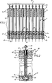
- Fig. 1 einen ausschnittsweisen Längsschnitt durch einen Prüfadapter gemäß einem Ausführungsbeispiel der Erfindung,
- Fig. 2 einen vergrößerten, gebrochenen Ausschnitt aus Fig. 1,
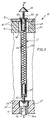
- Fig. 3 einen Prüfadapter in ausschnittsweiser, geschnittener Darstellung gemäß einem weiteren Ausführungsbeispiel der Erfindung, wobei von diesem Prüfadapter lediglich ein einziger Federkontaktstift dargestellt ist.
- 1 is a partial longitudinal section through a test adapter according to an embodiment of the invention,
- 2 shows an enlarged, broken section of FIG. 1,
- Fig. 3 shows a test adapter in a cutaway section according to a further exemplary embodiment of the invention, only a single spring contact pin being shown of this test adapter.
Die in der Zeichnung ausschnittsweise dargestellten Prüfadapter 10 bzw. 10' weisen außer den dargestellten, in allen Teilen metallischen Federkontaktstiften 11 bzw. 11' im allgemeinen noch eine sehr große Anzahl entsprechender Federkontaktstifte 11 bzw. 11' auf. Zusätzlich können sie noch außer diesen "normalen" Federkontaktstiften 11 bzw. 11' noch elektrisch leitfähige Sonderkontaktstifte, bspw. pneumatische, metallische Kontaktstifte, aufweisen, falls dies erwünscht oder notwendig ist, die auch anders ald die dargestellten "normalen" Kontaktstifte 11 bzw. 11' befestigt sein können. Alle Kontaktstifte 11 bzw. 11' bilden "elektrische Leiter", die im Prüfadapter 10 bzw. 10' gegeneinander elektrisch isoliert lösbar angeordnet sind, so daß jeder Federkontaktstift 11 bzw. 11' im ganzen auswechselbar ist.The
Bei den dargestellten Prüfadaptern 10 bzw. 10' kann es sich vorzugsweise um sogenannte Universaladapter handeln, bei denen jeder einzelne Punkt eines einheitlichen Rasters mit einem Federkontaktstift 11 bzw. 11' besetzt ist, von denen beim Prüfen einer Sorte von Prüflingen nur jeweils die für die Prüfung auf deren Fehlerfreiheit benötigten Kontaktstifte vom Auswerter berücksichtigt werden. Die Erfindung ist jedoch auch bei anderen Prüfadaptern vorteilhaft anwendbar, deren Kontaktstifte jeweils entsprechend dem Muster der Prüfstellen nur einer Sorte von Prüflingen zugeordnet sind, so daß dann jeweils alle Kontaktstifte an der Prüfung dieser Prüflinge mitwirken. Auch andere Möglichkeiten bestehen.The
In jedem Fall ist die Anzahl der Federkontaktstifte, wie 11 bzw. 11', pro Prüfadapter 10 bzw. 10' sehr groß und beträgt meist mindestens einige tausend, vorzugsweise einige zehntausend oder in manchen Fällen sogar mehr als hunderttausend Federkontaktstifte 11 bzw. 11'.In any case, the number of spring contact pins, such as 11 or 11 ', per
Der Prüfadapter 10 nach Fig. 1 und 2 weist einen nicht näher dargestellten Rahmen auf, an welchem insgesamt vier ebene, zueinander parallele Scheiben 12, 13, 14 und 15 befestigt sind, die paarweise zwei Gesamtplatten 16 bzw. 17 bilden, von denen jede aus den zwei aneinander anliegenden Einzelscheiben 12, 13 bzw. 14,15 gebildet ist. Die einem jeweils zu prüfenden elektrischen oder elektronischen Prüfling, wie 18, bei dem es sich bspw. um eine Leiterplatte, um eine sonstige Schaltung oder dergl. handeln kann, benachbarte Gesamtplatte 16 sei als Frontgesamtplatte 16 bezeichnet und besteht aus der aus elektrisch isolierendem Kunststoff bestehenden Positionierscheibe 12 und der an deren Rückseite anliegenden und diese über ihre Breite und ihre Länge abstützenden Viel dickeren starren Stützplatte 13. Diese dicke Stützplatte 13 kann zweckmäßig aus hochfestem, starren Kunststoff oder auch aus anderen starren, hochfesten Materialien, wie Metall, Keramik oder dergl. bestehen. Falls sie aus Metall besteht, kann sie vorzugsweise einen elektrisch isolierenden Überzug aufweisen, bspw. zweckmäßig aus hartem Aluminium bestehen, das an der Oberfläche anodisch oxidiert ist.The
Die beiden Scheiben 14, 15 der rückwärtigen Gesamtplatte 17 bestehen aus elektrisch isolierendem Kunststoff, von denen die dünnere eine Positionierscheibe 14 und die viel dickere eine starre Stützplatte 15 ist. Jeder metallische Federkontaktstift 11 (wie auch 11') bildet einen "elektrischen Leiter" geringen ohm'schen Durchgangswiderstandes. Der einzelne Federkontaktstift 11 besteht im Ausführungsbeispiel nach Fig. 1 und 2 aus einem dünnen, langen kreiszylindrischen metallischen Gehäuse 19, dessen obere Stirnseite mit einem Ringflansch oder Ringbund 20 auf der dem jeweiligen Prüfling 18 zugewendeten Außenoberfläche der oberen Positionierscheibe 12 zur axialen Abstützung dieses Gehäuses 19 aufliegt, wobei diese Positionierscheibe 12 ihrerseits durch die Stützplatte 13 gegen Wölben abgestützt ist. Im metallischen Gehäuse 19 ist ein metallischer Kolben 21 gleitbar gelagert, dessen aus dem Gehäuse 19 nach oben überstehende metallische Kolbenstange 22 eine metallische Kontaktspitze 23 aufweist, die dem Kontaktieren der ihr jeweils zugeordneten Prüfstelle von zu prüfenden Prüflingen 18 dient. Der Kolben 21 wird durch eine sich am Boden des Gehäuses 19 abstützende metallische Druckfeder 24 in aufwärtiger Richtung federbelastet. Der untere Endbereich des Gehäuses 19 ist in einer Durchgangsbohrung 30 der unteren Positionierscheibe 14 zu seiner rückwärtigen radialen Positionierung mit geringem Gleitlagerspiel gelagert. An den Boden des Gehäuses 19 ist ein dünner stabförmiger Metallstab 25 einstükkig mit angeformt, der an dem Kopf 26' eines in die dicke Stützplatte 15, die aus hochfestem, starren, elektrisch isolierenden Kunststoff besteht, der rückwärtigen Gesamtplatte 17 eingesetzten metallischen Kontaktes 26 mit für guten elektrischen Kontakt ausreichender Kraft anliegt, indem dieser Kopf 26' durch eine ihn aufwärts belastende Biegefeder 27 an den Stab 25 angedrückt ist. Es ist auch möglich, diese Stäbe 25 des Gehäuses 19 durch die rückwärtige Gesamtplatte 17 unter Weglassung der Kontakte 26 hindurchzuführen und sie an die zum Auswerter weiterführenden elektrischen Leitungsdrähte 33 direkt anzuschließen bwsp. anzulöten oder sonstige elektrische Anschlüsse hierfür vorzusehen. In Fig. 1 sind die zum nicht dargestellten Auswerter weiterführenden Leitungsdrähte 33 an die Kontakte 26 angeschlossen. Jeder der beiden dünnen und hierdurch vorzugsweise biegsamen Positionierscheiben 12 und 14 der Frontgesamtplatte 16 und der rückwärtigen Gesamtplatte 17 sind für jeden Federkontaktstift 11 mit je einer gebohrten Durchgangsbohrung 29,30 versehen, deren Durchmesser dem Außendurchmesser des zylindrischen Gehäuses 19 des jeweiligen Federkontaktstiftes 11 ungefähr entspricht, so daß hierdurch das Gehäuse 19 jedes Federkontaktstiftes 11 sowohl an seinem oberen Ende als auch an seinem unteren Ende genau positioniert und damit jeder Federkontaktstift 11 genau radial und axial positioniert ist und auch genau rechtwinklig zu den Ebenen der zueinander parallelen Gesamtplatten 16, 17 steht. Die Durchgangslöcher 29 für die Federkontaktstifte 11 der oberen Positionierscheibe 12 können dabei so dimensioniert sein, daß sie die Gehäuse 19 reibungsschlüssig lösbar halten, d.h. daß sie durch die von den Kontakten 26 ausgeübten axialen Kräfte nicht gegen den Reibungsschluß verschoben werden können, jedoch sich mittels eines an der Kolbenstange 22 oder dem Bund 20 angreifenden Werkzeuges axial aus den Gesamtplatten 16,17 zum Auswechseln oder sonstigem Abnehmen herausziehen lassen. Da diese Positionierscheiben 12 und 14 relativ dünn sind, vorzugsweise ihre Dicken jeweils 2 bis 5 mm betragen können, sind diese Durchgangsbohrungen 29, 30 in ihnen leicht und kostengünstig trotz ihrer geringen Durchmesser von vorzugsweise 0,2 bis 1,4 mm, inbesondere von etwa 0,3 bis 1,0 mm zu bohren. Die infolge ihrer geringen Dicke relativ geringe Steifigkeit dieser Positionierscheiben 12, 14 wird ausgeglichen durch die Starrheit der sie jeweils ungefähr über ihre Breiten und Längen stützenden, viel dickeren starren Stützplatten 13, 15. Die untere Stützplatte 15 kann aus hochfestem Kunststoff oder aus Metall mit einem es elektrisch isolierenden Überzug oder dergl. hergestellt sein. Die Dicken der Stützplatten 13,15 können bspw. zweckmäßig 15 bis 40 mm betragen. Die Länge der Kontaktstifte 11 ist wie dargestellt viel größer als die Dicke der Gesamtplatten 16,17. Die in den Stützplatten 13, 15 befindlichen Durchgangslöcher, wie 40 und 41, die von den Federkontaktstiften 11 nicht kontaktiert werden und gleichachsig zu den mit ihnen fluchtenden Durchgangslöchern 29,30 der Positionierscheiben 12,14 sind, sind in ihren Durchmessern soviel größer als die Durchgangsbohrungen 29,30 der Positionierscheiben 12, 14, daß sie trotz der wesentlich größeren Dicke dieser Stützplatten 13, 15 ebenfalls kostengünstig gebohrt werden können.The two
In dem Ausführungsbeispiel nach Fig. 1 und 2 ist es nicht oder nicht immer notwendig, die Scheiben 12 und 13 - bzw. die Scheiben 14 bzw. 15 - so miteinander zu verbinden, daß ihre einander benachbarten Flächen 42, 43 bzw. 44, 45 über ihre Breiten und Längen fest zusammengehalten sind. Doch kann dies erforderlichenfalls vorgesehen sein, vorzugsweise durch Zusammenkleben ihrer einander gegenüberliegenden Flächen, bspw. wenn die von den Kontakten 26 auf die Gehäuse 19 ausgeübten Kräfte relativ groß sind. Als Kleber können vorzugsweise Haftkleber vorgesehen sein.In the exemplary embodiment according to FIGS. 1 and 2, it is not or not always necessary to connect the
In Fig. 3 ist eine Ausführungsform eines Prüfadapters 10' ausschnittsweise dargestellt, welche sich von der nach Fig. 1 und 2 insbesondere in der Ausbildung der Federkontaktstifte, wie 11', und der rückwärtigen Gesamtplatte 17' unterscheidet. Die rückwärtige Gesamtplatte 17' besteht in diesem Ausführungsbeispiel aus einer einzigen einstückigen starren Platte 17', in die metallische elektrische Kontakte 26", wie dargestellt, vorzugsweise fest, eingesetzt sind. Jeder Kontakt 26" weist dabei einen zylindrischen Kopf 26" größeren Durchmessers auf, an den ein zylindrischer Schaft 26a etwas kleineren Durchmessers anschließt, der über diese rückwärtige Gesamtplatte 17' nach unten etwas übersteht, und hier kann dann ein zum Auswerter weiterführende Leitungsdraht 33 angelötet oder auf sonstige Weise elektrisch angeschlossen sein. Dieser Kontakt 26" dient gleichzeitig dem rückwärtigen genauen Positionieren des dargestellten Federkontaktstiftes 11', indem im rückwärtigen Längsendbereich des kreiszylindrischen Gehäuses 19 ein zweiter Kolben 21' gleitbar geradegeführt gelagert ist, der mit einer Kolbenstange 22' nach unten durch eine Bohrung des Gehäusebodens aus dem Gehäuse 19 herausragt. Auf diesen zweiten Kolben 21' stützt sich eine Druckfeder 24 ab, die auch den im oberen Längsendbereich des Gehäuses 19 gleitbar geradegeführt gelagerten ersten Kolben 21 belastet, welcher die Kolbenstange 22 und die an der Kolbenstange 22 befindliche Kontaktspitze 23 dieses Federkontaktstiftes 11' trägt. Die Druckfeder 24 belastet also beide Kolben 21, 21' gleichzeitig und drückt sie in voneinander wegführender Richtung. Die in einer Spitze auslaufende Kolbenstange 22' des unteren Kolbens 21' wird durch die Feder 24 in eine kegelförmige Pfanne des Kopfes 26" des Kontaktes 26" zu ihrer Justierung gedrückt. Durch diese Justierung ist es nicht erforderlich, eine gesonderte Positionierscheibe auf dieser unteren Platte 17' anzuordnen. Auch wirkt hierdurch die auf die Kontaktspitze 23 beim Prüfen eines Prüflinges von diesem axial ausgeübte Kraft (Pfeil P), durch die der obere Kolben 21 zusammen mit der Kontaktspitze 23 etwas nach unten gegen die Kraft der Feder 24 gedrückt wird, nicht über das an der Positionierscheibe 12 mittels seines Ringflansches 20 abgestützten Gehäuse 19, sondern über den unteren Kolben 21' und die untere Kolbenstange 22' auf den in der unteren Platte 17' verankerten Kontakt 26", so daß die untere Gesamtplatte 17' diese axiale Belastungskraft P der Kontaktspitze 23 im Betrieb im wesentlichen aufnimmt und hiervon die ebene Gesamtfrontplatte 16 entlastet ist. Die wie bei Fig. 1 und 2 ausgebildete, aus einer dünnen Positionierscheibe 12 und einer diese stützenden dicken Stützplatte 13 bestehende Frontgesamtplatte 16 ist durch die Kontaktstifte 11' belastet und kann auch bei der Prüfung durch Kräfte, insbesondere Reibungskräfte in Richtung der Pfeile P mit belastet werden. Es können hier besonders zweckmäßig die Flächen 42 und 43 der Positionierscheibe 12 und der Stützplatte 13 fest zusammengehalten sein, bspw. durch Kleben. Der Kolben 21 ist in seiner oberen Stellung, in der er an der Decke des Gehäuses 19 anliegt, durch die Druckfeder 24 gegen diese Decke gedrückt, was sich in einer auf das Gehäuse 19 axial nach oben wirkenden Belastung auswirkt. Das Gehäuse 19 kann gegen Verschieben nach oben gehalten werden. Dies kann vorzugsweise dadurch erfolgen, indem der Durchmesser der Durchgangsbohrung 29 der oberen Positionierscheibe 12 so auf den Durchmesser des in ihr befindlichen Gehäuseabschnittes abgestimmt ist, daß dieses Gehäuse 19 in dieser Positionierscheibe 12 durch Haftreibung ausreichend fest gehalten ist, um sich nicht durch den Druck der Feder 24 nach oben verschieben zu lassen, wobei dieser Reibungssitz jedoch nur so fest ist, daß er nicht das Auswechseln des Federkontaktstiftes 11' im ganzen behindert. Die Stützplatte 13 bewirkt hier also, daß sie bei unbelasteter Kontaktspitze 23 im Falle fest zusammengehaltener Flächen 42, 43 Auswölben der Positionierscheibe 12 durch die Kräfte der Federn 24 nach oben verhindert, und bei nach unten gedrückten Kontaktspitzen 23 stützt sie die Positionier scheibe 12 gegen Auswölben nach unten ab. Auch das Verhindern des Auswölbens der Scheibe 12 nach oben durch die Stützplatte 13 sei als Stützung der Scheibe 12 durch die Platte 13 bezeichnet.In Fig. 3, an embodiment of a test adapter 10 'is shown in detail, which differs from that of FIGS. 1 and 2 in particular in the design of the spring contact pins, such as 11', and the rear overall plate 17 '. In this exemplary embodiment, the rear overall plate 17 'consists of a single, one-piece rigid plate 17', into which metallic
Obwohl in den Ausführungsbeispielen die Positionierscheiben 12 der Frontgesamtplatten 16 die jeweils den Kontaktspitzen 23 der Kontaktstifte 11, 11' benachbarten Scheiben sind, was meist besonders vorteilhaft ist, kann in manchen Fällen es auch zweckmäßig sein, die Stützplatte 13 der Frontgesamtplatte 16 benachbart den Kontaktspitzen 23 der Kontaktstifte 11 bzw. 11' anzuordnen. So ist im Ausführungsbeispiel nach Fig. 3 bei unbelasteten Kontaktspitzen 23 das an der oberen Positionierscheibe 12 reibungsschlüssig gehaltene Gehäuse 19 durch die Feder 24 mit deren Vorspannung in aufwärtiger Richtung belastet und es kann dann oft vorteilhaft sein, die Positionierscheibe 12 unter der Stützplatte 13, d.h. auf ihrer der rückwärtigen Gesamtplatte 17' zugewendeten Seite, anstatt, wie dargestellt, über ihr anzuordnen.Although in the exemplary embodiments the
Bei dem Ausführungsbeispiel nach Fig. 1 und 2 ist insbesondere dann keine feste Verbindung, bspw. keine Verkleben, der aneinander anliegenden Flächen der Positionierscheibe 12 und der Stützplatte 13 erforderlich, wenn die Drähte 33 direkt unter Weglassung der Kontakte 26 an die Anschlußenden 25 der Federkontaktstifte 11 angeschlossen sind, und es kann dann oft auch die Stützplatte 15 und in manchen Fällen auch die Positionierscheibe 14 weggelassen werden.In the embodiment of FIGS. 1 and 2, in particular, no firm connection, for example no gluing, of the abutting surfaces of the
In den beschriebenen Ausführungsbeispielen nach den Fig. 1 bis 3 dient die jeweils als Platte ausgebildete Positionierscheibe 12 der Frontgesamtplatte 16 sowohl der axialen als auch der radialen Positionierung des Gehäuses 19 in ihrem Bereich und auch dem Halten des Gehäuses gegen die von der Feder 24 ausgeübten und sonstigen im Betrieb auftretenden Kräfte. Es ist jedoch auch möglich, vorzusehen, daß das Gehäuse 19 des Federkontaktstiftes 11 bzw. 11' in der zugeordneten Bohrung 29 der Positionierscheibe 12 mit geringem Gleitlagerspiel axial beweglich angeordnet ist, was das Einsetzen und Herausnehmen des Federkontaktstiftes noch weiter erheblich erleichtert und vereinfacht. Diese Positionierscheibe 12 dient dann zwar weiterhin dem ständigen radialen Positionieren des Gehäuses 19 in ihr. Sie braucht jedoch nicht mehr dem ständigen axialen Halten des Federkontaktstiftes zu dienen. Sie dient dabei jedoch noch dem axialen Abstützen des Gehäuses 19 in Abwärtsrichtung, sei es ständig oder nur während Prüfvorgängen, bei denen die Kontaktspitze 23 mit dem Kolben 21 durch Prüflinge nach unten gedrückt wird. Dies sei anhand von nicht dargestellten Abwandlungen der Fig. 2 und 3 an einigen Ausführungsbeispielen noch näher erläutert.In the described exemplary embodiments according to FIGS. 1 to 3, the
In solchen Fällen ist vorgesehen, daß der Prüfadapter 10, 10' nur in solcher Stellung oder Stellungen eingesetzt wird, bei der oder denen die Kontaktspitzen 23 der Federkontaktstifte 11 bzw. 11' vertikal oder schräg nach aufwärts gerichtet sind, so daß die Federkontaktstifte, wenn ihre Gehäuse 19 in den zugeordneten Durchgangslöchern der Positionierscheiben 12 der Frontgesamtplatten mit geringem Gleitlagerspiel geführt sind und sie auch nicht an anderen Stellen, bspw. an der rückwärtigen Gesamtplatte 17 gegen Abnehmen von ihr gesichert sind, nicht aus dem Prüfadapter 10, 10' herausfallen können, sondern sich infolge ihres Eigengewichtes im Prüfadapter halten, sei es durch Abstützung an der Frontgesamtplatte 16 mittels ihrer Gehäuseringbunde 20 oder sonstiger Verbreiterungen der Gehäuse 19 an dieser Stelle und/oder durch Abstützung an der unteren Gesamtplatte 17 bzw. auf oder an elektrischen Kontakten od. dergl., die an der Gesamtplatte 17 oder auf sonstige Weise gehalten sein können.In such cases, it is provided that the
Beim Ausführungsbeispiel nach Fig. 1 und 2 ist also dann das Gehäuse 19 nicht nur in der Durchgangsbohrung 30 der unteren Positionierscheibe 14 mit geringem Gleitlagerspiel geführt, sondern auch in der Durchgangsbohrung 29 der oberen Positionierscheibe 12. Die Feder 27 kann dann bei unbelasteter Kontaktspitze 23 den Federkontaktstift 11 unter Abheben des Ringbundes 20 seines Gehäuses 19 von der Positionierscheibe 12 nach oben drücken. Wenn ein Prüfling bei einer Prüfung die Kontaktspitze 23 mit dem Kolben 21 jedoch nach unten drückt, wird hierdurch der Kolben 21 relativ zum Gehäuse axial nach unten unter stärkerem Zusammendrücken der Feder 24 gedrückt, und diese Feder 24 drückt das Gehäuse 19 und damit den Metallstab 25 axial nach unten gegen den Kontakt 26', welcher so unter stärkerem Zusammendrücken der Feder 27 mit entsprechend großer Kraft durch den Metallstab 25 belastet wird, so daß hier guter elektrischer Kontakt während jedes Prüfvorganges besteht. Dabei ist auch zu berücksichtigen, daß der den Federkontaktstift 11 durchströmende Prüfstrom bei solchen Prüfungen in der Regel immer erst dann eingeschaltet wird, wenn der zu prüfende Prüfling seine die Kontaktspitze 23 des Federkontaktstiftes 11 am weitesten nach unten drückende Endstellung erreicht hat, in der die Prüfung durchgeführt wird.1 and 2, the
Es ist bei der Ausführungsform nach Fig. 1 und 2 jedoch oft auch eine Abwandlung zweckmäßig, bei der der elektrische Kontakt 26 nicht durch die Feder 27 etwas nach oben federnd gedrückt ist, sondern in der unteren Stützplatte 15 unbeweglich gehalten oder zumindest gegen axiale Relativverschiebung nach unten gehalten ist, zu welchem Zweck die Feder 27 weggelassen wird und der Kopf 26' mit seinem unteren Bund auf der Ringschulter der Durchgangsbohrung 41 der Stützplatte 15 aufsitzen kann. Es kann auch vorgesehen sein, die Feder 24 kürzer als dargestellt zu treffen, derart, daß der Kolben 21 nicht an die den Ringbund 20 aufweisende obere Stirnwand des Gehäuses gedrückt wird, sondern sich der Kolben 21 ständig im Abstand unterhalb der oberen Stirnwand des Gehäuses 19 befindet.1 and 2, however, it is often also expedient to have a modification in which the
Ähnliche Abwandlungen können auch bei der Ausführungsform nach Fig. 3 vorgesehen sein. So kann hier ebenfalls die Feder 24 so kurz sein, daß der Kolben 21 bei nach oben gerichteter Kontaktspitze 23 nicht an der den Ringbund 20 aufweisenden oberen Stirnwand des Gehäuses 19 zur Anlage kommt, sondern sich im Abstand von ihr befindet, bspw. in der unbelasteten Stellung der Kontaktspitze 23 im Abstand von 1 bis 2 mm. Das Gehäuse 19 kann ebenfalls in der zugeordneten Durchgangsbohrung 29 der Positionierscheibe 12 mit Gleitlagerspiel gelagert sein. Der Ringbund 20 liegt dann ständig infolge des Eigengewichtes des Gehäuses 19 auf der Oberseite der Positionierscheibe 12 auf. Das Anschlußende 22' liegt bei unbelasteter Kontaktspitze 23 dann nur mit dem Eigengewicht des Federkontaktstiftes 11' abzüglich des Gewichtes seines Gehäuses 19 auf dem Kontakt 26" auf. Wenn jedoch bei Durchführung einer Prüfung der Federkontaktstift 23 durch den Prüfling mit der Kraft P nach unten unter Zusammendrücken der Feder 24 gedrückt wird, wird hierdurch das Anschlußende 22' mit entsprechend großer Kraft auf den Anschlußkontakt 26" axial angedrückt und hierdurch ebenfalls wieder guter elektrischer Kontakt während der einzelnen Prüfvorgänge von Prüflingen sichergestellt.Similar modifications can also be provided in the embodiment according to FIG. 3. The
Das Ausführungsbeispiel nach Fig. 3 kann auch noch in anderer Weise abgewandelt werden, wobei ebenfalls die Kontaktspitze 23 nach oben gerichtet ist und das Gehäuse 19 in der Durchgangsbohrung der Positionierscheibe 12 mit engem Gleitlagerspiel geführt ist. Bei dieser Abwandlung ist die Feder 24 so lang, daß sie bei unbelasteter Kontaktspitze 23 den oberen Kolben 21 bis zum Anliegen an die den Ringbund 20 aufweisende obere Stirnwand des Gehäuses 19 drückt, und das Gehäuse 19 etwas nach oben bewegt wird, bis der Kolben 21' an dem Boden des Gehäuses 19 zur Anlage kommt. Hierdurch wird der Ringbund 20 von der Positionierscheibe 12 nach oben entsprechend weit abgehoben. Die Feder 24 ist ständig vorgespannt. Wenn nun die Kontaktspitze 23 durch einen Prüfling mit dem Kolben 21 nach unten bewegt wird, dann kann das Gehäuse 19 axial nach unten wandern, bis sein Ringbund 20 auf der Positionierscheibe 12 aufliegt. Der Boden des Gehäuses 19 befindet sich dann, wie in Fig. 3, im Abstand unterhalb des Kolbens 21', und dieser Kolben 21' wird mit einer der axialen Belastungskraft P der Kontaktspitze 23 ungefähr entsprechenden Kraft nach unten und damit das Anschlußende 22' mit entsprechender Kraft an den Anschlußkontakt 26" gedrückt. Diese starke Anpreßkraft tritt also ebenfalls nur während jeder einzelnen Prüfung auf und, solange die Kontaktspitze 23 nicht belastet ist, ist die Kraft, mit der das Anschlußende 22' an den Anschlußkontakt 26" axial angedrückt wird, nur gering, nämlich etwa entsprechend dem Eigengewicht des Federkontaktstiftes 11'.The embodiment according to FIG. 3 can also be modified in another way, whereby the
Die Lagerung des Gehäuses 19 in der Durchgangsbohrung der Positionierscheibe 12 mit geringem Gleitlagerspiel hat u.a. den Vorteil, daß bei weiterhin guter radialer Positionierung dieses Gehäuses 19 in der Positionierscheibe 12 das Auswechseln des Federkontaktstiftes 11, 11' noch einfacher und rascher erfolgen kann, weil beim Herausziehen des Federkontaktstiftes 11 bzw. 11' aus dem Prüfadapter praktisch nur das Eigengewicht und keine größere Haftreibung des Federkontaktstiftes 11 bzw. 11' im Prüfadapter 10 bzw. 10' zu überwinden ist. Die Frontgesamtplatte 16 ist dann auch durch die Federkontaktstifte 11 bzw. 11' geringer belastet und die Stützplatte 13 und die Positionierscheibe 12 können hierdurch dünner ausgeführt werden, was ihre Herstellung verbilligt. Diese Stützplatte 13 ist jedoch weiterhin vorzusehen, weil sie für die genaue Positionierung und Abstützung der Scheibe 12 weiterhin notwendig oder zweckmäßig ist. Auch genügt es bei den vorbeschriebenen Abwandlungen der Fig. 1 bis 3 zumindest oft, wenn die Positionierscheibe 12 nur auf der Stützplatte 13 aufliegt, ihre einander benachbarten Flächen also nicht durch Kleben oder auf sonstige Weise über ihre Flächenerstreckungen zusammengehalten sind. Dann genügt also, wenn die beiden Scheiben 12 und 13 nur an ihren Randbereichen am Gestell des Prüfadapters gehalten und keine sonstigen Verbindungsmittel zwischen ihnen vorgesehen sind. Oder es genügt, sie nur an ihren Randbereichen so miteinander zu verbinden, daß sie eine in das Gestell des Prüfadapters einsetzbare Baueinheit bilden. Es kann also bevorzugt vorgesehen sein, daß die Positionierscheibe 12 und die Stützplatte 13 der Frontgesamtplatte 16 nur außerhalb ihrer der Aufnahme der Kontaktstifte 11 bzw. 11' dienenden Bereiche zusammengehalten sind, sei es direkt zur Bildung einer in das Gestell des Prüfadapters einsetzbaren Baueinheit oder indirekt mittels des Gestells des Prüfadapters oder auf sonstige Weise. Wenn die Positionierscheibe 12 im wesentlichen nur mit dem Eigengewicht der Kontaktstifte 11 oder ihrer Gehäuse zuzüglich Reibungskräften des oder der Kolben belastet ist, kann sie besonders dünn ausgebildet werden, so daß sie dann keine Platte mehr ist, sondern nur noch eine dünne bis extrem dünne Scheibe, oft zweckmäßig nur noch ein Blatt oder eine Folie sein kann, was ihre Herstellung noch weiter verbilligen kann.The bearing of the
Jeder der dargestellten Federkontaktstifte 11,11' weist ein Gehäuse 19 mit einem einzigen zylindrischen Mantel auf, an den obenseitig ein Ringbund 20 anschließt. Dieser Mantel ist direkt in die zugeordnete Bohrung 29 der betreffenden Positionierplatte 12 eingesetzt. Es ist aber auch möglich, diesen Mantel des Kontaktstiftes als Innenmantel in eine einen Außenmantel des Gehäuses bildende Hülse-oder dergl. formschlüssig lösbar einzusetzen, die in die Bohrung 29 eingesetzt wird und kürzer, gleich lang oder länger als der Innenmantel sein kann, so daß dann das Gehäuse des Kontaktstiftes, welcher Kontaktstift ein Federkontaktstift oder ein sonstiger Kontaktstift sein kann, einen Außenmantel und einen Innenmantel aufweist. Dieser Außenmantel kann bspw. einen Ringflansch aufweisen, der an der Oberseite der Frontgesamtplatte anliegt.Each of the spring contact pins 11, 11 'shown has a
Anstelle der Federkontaktstifte 11,11' mit langen Gehäusen 19 oder zusätzlich können auch Kontaktstifte anderer Bauarten vorgesehen werden. Bspw. kann die Kontaktspitze oft die Spitze einer langen, starren oder in sich axial federnden Kontaktnadel oder eines als Kontaktstift dienenden Drahtes sein, die bzw. der in dem Längsabschnitt 29 des kleineren Durchmessers der Frontgesamtplatte, d.h. im Falle der in den Ausführungsbeipielen dargestellten Frontgesamtplatten in der zugeordneten Bohrung 29 der Positionierscheibe 12 gleitbar axial geführt oder im Bereich der Positionierscheibe 12 in einer in die zugeordnete Durchgangsbohrung 29 dieser Positionierscheibe eingesetzten, vorzugsweise kurzen metallischen oder nichtmetallischen Führungshülse mit geringem Gleitlagerspiel geradegeführt ist. Diese Führungshülse kann sich im wesentlichen nur über die Länge der Durchgangsbohrung 29 erstrecken oder auch beliebig länger sein. Diese Kontaktnadel kann, wenn sie starr ist, bspw. sich an einer an der rückwärtigen Gesamtplatte abstützenden, freiliegenden Rückstellfeder federnd abgestützt sein.Instead of the spring contact pins 11, 11 'with
Die Positionierscheibe kann bspw. vorteilhaft aus elektrisch isolierendem, leicht und genau zu bohrendem polymerem Methacrylsäuremethylester, wie er von Firma Röhm & Haas, Darmstadt, unter dem Handelsnamen Plexiglas vertrieben wird, und die Stützplatte aus hochfestem, glasfaserverstärktem Epoxidharz bestehen, das zwar schwerer als Plexiglas zu bohren ist, was jedoch wegen der größeren Bohrungsdurchmesser und der hier dann vorzugsweise geringeren Bohrungstiefe und der geringeren erforderlichen Bohrungsgenauigkeit ebenfalls kostengünstig möglich ist.The positioning disk can, for example, advantageously consist of electrically insulating, easy and precise drilling of polymeric methacrylic acid, as it is sold by Röhm & Haas, Darmstadt, under the trade name Plexiglas, and the support plate can consist of high-strength, glass fiber reinforced epoxy resin, which is heavier than Plexiglas is to be drilled, but this is also possible inexpensively because of the larger bore diameter and the then preferably smaller hole depth and the lower required hole accuracy.
Wie aus der Zeichnung ferner ersichtlich ist, sind die Bohrungen 40, 41 der Stützplatten 13,15 unabgedeckt, also jeweils nach unten offen, was besonders zweckmäßig ist.As can also be seen from the drawing, the
Die Länge des einzelnen Kontaktstiftes 11 bzw. 11' kann zweckmäßig mindestens das 3-fache, vorzugsweise mindestens das 4-fache der Dicke der Frontgesamtplatte 16 betragen. Auch dann, wenn der Kontaktstift keine Federkontaktstift ist, sondern ein anders ausgebildeter Kontaktstift, kann seine Länge ebenfalls zweckmäßig mindestens das 3-fache, vorzugsweise mindestens das 4-fache der Dicke der Frontgesamtplatte betragen.The length of the
Claims (19)
Priority Applications (1)
| Application Number | Priority Date | Filing Date | Title |
|---|---|---|---|
| AT86100780T ATE53672T1 (en) | 1985-01-22 | 1986-01-22 | TEST ADAPTER. |
Applications Claiming Priority (2)
| Application Number | Priority Date | Filing Date | Title |
|---|---|---|---|
| DE3501874 | 1985-01-22 | ||
| DE3501874 | 1985-01-22 |
Publications (2)
| Publication Number | Publication Date |
|---|---|
| EP0189179A1 EP0189179A1 (en) | 1986-07-30 |
| EP0189179B1 true EP0189179B1 (en) | 1990-06-13 |
Family
ID=6260363
Family Applications (1)
| Application Number | Title | Priority Date | Filing Date |
|---|---|---|---|
| EP86100780A Expired - Lifetime EP0189179B1 (en) | 1985-01-22 | 1986-01-22 | Test adapter |
Country Status (4)
| Country | Link |
|---|---|
| EP (1) | EP0189179B1 (en) |
| AT (2) | AT395485B (en) |
| DE (1) | DE3671974D1 (en) |
| FR (1) | FR2576422B1 (en) |
Cited By (1)
| Publication number | Priority date | Publication date | Assignee | Title |
|---|---|---|---|---|
| US6876530B2 (en) | 2001-01-12 | 2005-04-05 | Qa Technology Company, Inc. | Test probe and connector |
Families Citing this family (8)
| Publication number | Priority date | Publication date | Assignee | Title |
|---|---|---|---|---|
| US4884024A (en) * | 1985-11-19 | 1989-11-28 | Teradyne, Inc. | Test pin assembly for circuit board tester |
| DE3832410C2 (en) * | 1987-10-09 | 1994-07-28 | Feinmetall Gmbh | Contact device |
| SE457315B (en) * | 1987-11-16 | 1988-12-12 | Reinhold Strandberg | DEVICE FOR TESTING CIRCUITS |
| SE458005B (en) * | 1987-11-16 | 1989-02-13 | Reinhold Strandberg | PROCEDURE FOR TESTING CIRCUIT AND APPARATUS FOR PERFORMANCE OF TEST |
| DE4226069C2 (en) | 1992-08-06 | 1994-08-04 | Test Plus Electronic Gmbh | Adapter device for a test device for circuit boards |
| FR2777999B1 (en) * | 1998-04-28 | 2000-06-09 | St Microelectronics Sa | DEVICE FOR ELECTRICALLY CONNECTING AN ELECTRONIC COMPONENT BY RETRACTABLE POINTS |
| US6570399B2 (en) | 2000-05-18 | 2003-05-27 | Qa Technology Company, Inc. | Test probe and separable mating connector assembly |
| US20160107143A1 (en) | 2013-03-15 | 2016-04-21 | Siluria Technologies, Inc. | Catalysts for petrochemical catalysis |
Family Cites Families (4)
| Publication number | Priority date | Publication date | Assignee | Title |
|---|---|---|---|---|
| US4183609A (en) * | 1978-03-16 | 1980-01-15 | Luna L Jack | Insulator board for spring probe fixtures |
| DE2933862A1 (en) * | 1979-08-21 | 1981-03-12 | Paul Mang | DEVICE FOR ELECTRONICALLY CHECKING CIRCUIT BOARDS. |
| DE3115787A1 (en) * | 1981-03-06 | 1982-11-04 | Feinmetall Gmbh, 7033 Herrenberg | Contact device |
| DE3240415A1 (en) * | 1982-11-02 | 1984-05-03 | Siemens AG, 1000 Berlin und 8000 München | Pin arrays for automatic testers |
-
1986
- 1986-01-09 AT AT0003186A patent/AT395485B/en not_active IP Right Cessation
- 1986-01-22 DE DE8686100780T patent/DE3671974D1/en not_active Expired - Lifetime
- 1986-01-22 FR FR8600891A patent/FR2576422B1/en not_active Expired
- 1986-01-22 AT AT86100780T patent/ATE53672T1/en not_active IP Right Cessation
- 1986-01-22 EP EP86100780A patent/EP0189179B1/en not_active Expired - Lifetime
Cited By (1)
| Publication number | Priority date | Publication date | Assignee | Title |
|---|---|---|---|---|
| US6876530B2 (en) | 2001-01-12 | 2005-04-05 | Qa Technology Company, Inc. | Test probe and connector |
Also Published As
| Publication number | Publication date |
|---|---|
| FR2576422A1 (en) | 1986-07-25 |
| ATA3186A (en) | 1992-05-15 |
| EP0189179A1 (en) | 1986-07-30 |
| AT395485B (en) | 1993-01-25 |
| DE3671974D1 (en) | 1990-07-19 |
| ATE53672T1 (en) | 1990-06-15 |
| FR2576422B1 (en) | 1987-09-18 |
Similar Documents
| Publication | Publication Date | Title |
|---|---|---|
| EP0915344B1 (en) | Test head for microstructures with interface | |
| EP0263244B1 (en) | Apparatus for the electronic testing of printed circuits with contact points in an extremely fine raster (1/20th to 1/10th inch) | |
| DE3240916C2 (en) | Device for testing electrical circuit boards | |
| DE2845234C2 (en) | ||
| DE2707900C3 (en) | Universal adapter for devices for electrical testing of various printed circuits | |
| DE8534841U1 (en) | Device for electronic testing of circuit boards or the like. | |
| DE19832330A1 (en) | Test holder for integrated circuit with solder ball connections serving as test points | |
| EP0189179B1 (en) | Test adapter | |
| EP0224471B1 (en) | Device for testing printed-circuit boards | |
| EP0268969A1 (en) | Adapter for a device for testing printed circuit boards | |
| EP0278073B1 (en) | Probe for an adapter for a device for testing printed circuit boards | |
| EP1031841A2 (en) | Test adapter for contacting populated printed circuit boards | |
| EP0184619B1 (en) | Printed circuit testing device | |
| EP0331163A1 (en) | Contacting device for testing arrangements for testing circuit boards or the like | |
| EP0315707A1 (en) | Adapter for a device for electronic testing of printed circuit boards | |
| EP0915343B1 (en) | Service friendly contacting device | |
| DE3601732C2 (en) | ||
| DE8501493U1 (en) | Test adapter | |
| EP0237732B1 (en) | Spring-loaded contact pin for a testing apparatus | |
| EP0242542A1 (en) | Test adapter | |
| DE3832410C2 (en) | Contact device | |
| DE3722485C2 (en) | ||
| DE3533218C2 (en) | ||
| DE3906691A1 (en) | Contact-making device for testing devices for testing printed circuit boards or the like | |
| DE19748825B4 (en) | Test head with a contacting device |
Legal Events
| Date | Code | Title | Description |
|---|---|---|---|
| PUAI | Public reference made under article 153(3) epc to a published international application that has entered the european phase |
Free format text: ORIGINAL CODE: 0009012 |
|
| AK | Designated contracting states |
Kind code of ref document: A1 Designated state(s): AT CH DE LI |
|
| 17P | Request for examination filed |
Effective date: 19861115 |
|
| 17Q | First examination report despatched |
Effective date: 19881208 |
|
| GRAA | (expected) grant |
Free format text: ORIGINAL CODE: 0009210 |
|
| AK | Designated contracting states |
Kind code of ref document: B1 Designated state(s): AT CH DE LI |
|
| REF | Corresponds to: |
Ref document number: 53672 Country of ref document: AT Date of ref document: 19900615 Kind code of ref document: T |
|
| REF | Corresponds to: |
Ref document number: 3671974 Country of ref document: DE Date of ref document: 19900719 |
|
| PG25 | Lapsed in a contracting state [announced via postgrant information from national office to epo] |
Ref country code: AT Effective date: 19910122 |
|
| PG25 | Lapsed in a contracting state [announced via postgrant information from national office to epo] |
Ref country code: LI Effective date: 19910131 Ref country code: CH Effective date: 19910131 |
|
| PLBE | No opposition filed within time limit |
Free format text: ORIGINAL CODE: 0009261 |
|
| STAA | Information on the status of an ep patent application or granted ep patent |
Free format text: STATUS: NO OPPOSITION FILED WITHIN TIME LIMIT |
|
| 26N | No opposition filed | ||
| REG | Reference to a national code |
Ref country code: CH Ref legal event code: PL |
|
| PGFP | Annual fee paid to national office [announced via postgrant information from national office to epo] |
Ref country code: DE Payment date: 19911221 Year of fee payment: 7 |
|
| PG25 | Lapsed in a contracting state [announced via postgrant information from national office to epo] |
Ref country code: DE Effective date: 19931001 |