EP0188955A1 - Apparatus for regulating the amine charge onto a culumn for purifying natural gas - Google Patents
Apparatus for regulating the amine charge onto a culumn for purifying natural gas Download PDFInfo
- Publication number
- EP0188955A1 EP0188955A1 EP85402563A EP85402563A EP0188955A1 EP 0188955 A1 EP0188955 A1 EP 0188955A1 EP 85402563 A EP85402563 A EP 85402563A EP 85402563 A EP85402563 A EP 85402563A EP 0188955 A1 EP0188955 A1 EP 0188955A1
- Authority
- EP
- European Patent Office
- Prior art keywords
- amine
- quartz
- column
- absorption
- regulating
- Prior art date
- Legal status (The legal status is an assumption and is not a legal conclusion. Google has not performed a legal analysis and makes no representation as to the accuracy of the status listed.)
- Granted
Links
Images
Classifications
-
- B—PERFORMING OPERATIONS; TRANSPORTING
- B01—PHYSICAL OR CHEMICAL PROCESSES OR APPARATUS IN GENERAL
- B01D—SEPARATION
- B01D53/00—Separation of gases or vapours; Recovering vapours of volatile solvents from gases; Chemical or biological purification of waste gases, e.g. engine exhaust gases, smoke, fumes, flue gases, aerosols
- B01D53/14—Separation of gases or vapours; Recovering vapours of volatile solvents from gases; Chemical or biological purification of waste gases, e.g. engine exhaust gases, smoke, fumes, flue gases, aerosols by absorption
- B01D53/1456—Removing acid components
-
- B—PERFORMING OPERATIONS; TRANSPORTING
- B01—PHYSICAL OR CHEMICAL PROCESSES OR APPARATUS IN GENERAL
- B01D—SEPARATION
- B01D53/00—Separation of gases or vapours; Recovering vapours of volatile solvents from gases; Chemical or biological purification of waste gases, e.g. engine exhaust gases, smoke, fumes, flue gases, aerosols
- B01D53/14—Separation of gases or vapours; Recovering vapours of volatile solvents from gases; Chemical or biological purification of waste gases, e.g. engine exhaust gases, smoke, fumes, flue gases, aerosols by absorption
- B01D53/1412—Controlling the absorption process
-
- B—PERFORMING OPERATIONS; TRANSPORTING
- B01—PHYSICAL OR CHEMICAL PROCESSES OR APPARATUS IN GENERAL
- B01D—SEPARATION
- B01D53/00—Separation of gases or vapours; Recovering vapours of volatile solvents from gases; Chemical or biological purification of waste gases, e.g. engine exhaust gases, smoke, fumes, flue gases, aerosols
- B01D53/30—Controlling by gas-analysis apparatus
-
- C—CHEMISTRY; METALLURGY
- C10—PETROLEUM, GAS OR COKE INDUSTRIES; TECHNICAL GASES CONTAINING CARBON MONOXIDE; FUELS; LUBRICANTS; PEAT
- C10K—PURIFYING OR MODIFYING THE CHEMICAL COMPOSITION OF COMBUSTIBLE GASES CONTAINING CARBON MONOXIDE
- C10K1/00—Purifying combustible gases containing carbon monoxide
- C10K1/08—Purifying combustible gases containing carbon monoxide by washing with liquids; Reviving the used wash liquors
- C10K1/10—Purifying combustible gases containing carbon monoxide by washing with liquids; Reviving the used wash liquors with aqueous liquids
- C10K1/12—Purifying combustible gases containing carbon monoxide by washing with liquids; Reviving the used wash liquors with aqueous liquids alkaline-reacting including the revival of the used wash liquors
- C10K1/14—Purifying combustible gases containing carbon monoxide by washing with liquids; Reviving the used wash liquors with aqueous liquids alkaline-reacting including the revival of the used wash liquors organic
- C10K1/143—Purifying combustible gases containing carbon monoxide by washing with liquids; Reviving the used wash liquors with aqueous liquids alkaline-reacting including the revival of the used wash liquors organic containing amino groups
-
- G—PHYSICS
- G01—MEASURING; TESTING
- G01N—INVESTIGATING OR ANALYSING MATERIALS BY DETERMINING THEIR CHEMICAL OR PHYSICAL PROPERTIES
- G01N21/00—Investigating or analysing materials by the use of optical means, i.e. using sub-millimetre waves, infrared, visible or ultraviolet light
- G01N21/01—Arrangements or apparatus for facilitating the optical investigation
- G01N21/03—Cuvette constructions
- G01N21/05—Flow-through cuvettes
-
- G—PHYSICS
- G01—MEASURING; TESTING
- G01N—INVESTIGATING OR ANALYSING MATERIALS BY DETERMINING THEIR CHEMICAL OR PHYSICAL PROPERTIES
- G01N21/00—Investigating or analysing materials by the use of optical means, i.e. using sub-millimetre waves, infrared, visible or ultraviolet light
- G01N21/01—Arrangements or apparatus for facilitating the optical investigation
- G01N21/03—Cuvette constructions
- G01N21/09—Cuvette constructions adapted to resist hostile environments or corrosive or abrasive materials
-
- Y—GENERAL TAGGING OF NEW TECHNOLOGICAL DEVELOPMENTS; GENERAL TAGGING OF CROSS-SECTIONAL TECHNOLOGIES SPANNING OVER SEVERAL SECTIONS OF THE IPC; TECHNICAL SUBJECTS COVERED BY FORMER USPC CROSS-REFERENCE ART COLLECTIONS [XRACs] AND DIGESTS
- Y10—TECHNICAL SUBJECTS COVERED BY FORMER USPC
- Y10T—TECHNICAL SUBJECTS COVERED BY FORMER US CLASSIFICATION
- Y10T436/00—Chemistry: analytical and immunological testing
- Y10T436/12—Condition responsive control
Definitions
- the invention relates to a new process for regulating the charge of amine on an absorption column for the desulfurization of gases, taking into account the absorption rate of the gas to be eliminated on the amine. It also relates to the device which implements the method and in particular to the photometer cell which allows the measurement.
- the purification process using amine, gas containing hydrogen sulfide is well known to those skilled in the art.
- the gas to be purified is injected at the bottom of an absorption column in which it is brought into countercurrent contact with an amine solution.
- the purified gas is recovered at the head of the column and the amine charged with hydrogen sulfide leaves at the bottom of the column, to be regenerated and reinjected into the absorption column.
- the object of the present invention is to remedy these disadvantages.
- it provides a method for regulating the amine load, characterized in that said regulation is made as a function of the residual content in the amine of the gas to be eliminated, the sample being taken in the liquid phase inside. of the column.
- the invention also provides an installation for the implementation of this method comprising: a device for continuously sampling the amine sample, an amine introduction circuit and a system for controlling the amine flow rate .
- the analyzer circuit acts on the amine charge circuit according to the absorption rate of the gas to be eliminated on the amine.
- the analyzer comprises a photometer whose measurement cell is capable of withstanding high pressures and temperatures with a very short and adjustable optical path. It is thus possible to analyze the amine on which the hydrogen sulphide is absorbed, at the very heart of the column.
- the advantages obtained thanks to this invention are very important.
- the in situ measurement of the absorption rate of H, S on the amine makes it possible to regulate the amine load at the very moment when the reaction departs from a predetermined rate. In particular, in this way, any risk of flaring is avoided or at least the frequency is reduced.
- an almost perfect operating stability is obtained, hence an energy gain on pumping the charge on the one hand, on the regeneration of the amine on the other hand.
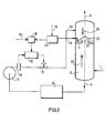
- FIG. 1 shows a gas desulphurization installation comprising an absorber (2), charge or discharge pipes (1), (3), (4) and (10), a charge pump for the amine (5), a regeneration unit (6), a tapping device (11) and a regulation system consisting of the analyzer (13), the addition module (18) and the regulator (19), a flow meter (16) and an automatic valve (17).
- the gas to be purified (25) containing hydrogen sulphide and possibly other acid compounds arrives via the line (1) and enters the bottom of an absorber (2) in which it is brought into contact against the current with a concentrated and hot amine solution (26) introduced through the line (10).
- the purified gas leaves the top of the absorber via line (3) and the amine solution, having fixed the acid compounds, is directed via line (4) to a regeneration unit (6). Once regenerated, the amine is pumped back by the charge pump (5) and then reinjected into the absorber.
- a tapping ( 1 1) leading to the liquid phase (21) is carried out at one of the plates (22) of the absorber.
- the sample is routed through a line where a pressure safety system has been provided to the analyzer (13).
- Said analyzer comprises a photometer whose cell is capable of withstanding high pressures, high temperatures and makes it possible to make measurements on very short and adjustable optical paths.
- the measurement, after adjustable amplification, of the saturation rate of the amine is compared to a setpoint - (14) previously fixed, and comes to modify by increasing or decreasing you, a flow rate setpoint (15), thanks to a addition module (18).
- the module output signal (18) is driving the set point of the flow regulating loop comprising the meter (16) of the controller (1 9) and automatic valve (17).
- Another embodiment of the amine flow control consists in acting not on the valve (17), but on the speed of the pump (5), for example by controlling the steam intake of a drive turbine or the speed of an electric motor by any appropriate means.
- the regulation device as described above, can only be envisaged with a measurement system specially designed to withstand high pressures and temperatures and which allows very short optical paths, because significant amounts of hydrogen sulfide absorbed on the amine are analyzed, not traces.
- the optical path must be easily adjustable in order to be able to adapt the sensitivity of the analysis to the characteristics of the column.
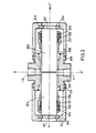
- FIG. 2 shows a preferred embodiment of a photometer cell which meets these requirements.
- the photometer cell is symmetrical with respect to a plane passing through the axis X'X and perpendicular to the optical axis YY '. It also has a symmetry of revolution around the axis YY '.
- the cell comprises two quartz cylinders (102) and - (202), their diameter corresponds to the internal diameter of two bodies (108) and (208) themselves nested and welded in the internal cylindrical cavity of a main body - ( 100).
- a socket (107) (respectively (207)) by wedging against the corresponding quartz cylinder a seal (105) (respectively (205)) and a seal (106) (respectively - (206)) in the shape of a bevel.
- the point of the bevel of said joint - (106) (respectively (206)) is wedged between the quartz and the end of the body (108) (respectively (208)) which is bevelled in opposite directions.
- the tip of the bevel of the seal (105) (respectively (205)) is wedged between the quartz and the other end of the seal (106) - (respectively (206)) which is bevelled in the opposite direction.
- the product to be analyzed enters through the hole (110) of axis XX 'formed in the main body, passes between the two quartz cylinders which determine the optical path and exits through the hole (111) also of axis XX'.
Abstract
Description
L'invention concerne un nouveau procédé de régulation de la charge d'amine sur une colonne d'absorption pour la désulfuration des gaz, tenant compte du taux d'absorption du gaz à éliminer sur l'amine. Elle se rapporte également au dispositif qui met en oeuvre le procédé et en particulier à la cellule du photomètre qui permet la mesure.The invention relates to a new process for regulating the charge of amine on an absorption column for the desulfurization of gases, taking into account the absorption rate of the gas to be eliminated on the amine. It also relates to the device which implements the method and in particular to the photometer cell which allows the measurement.
Le procédé d'épuration à l'aide d'amine, de gaz renfermant de l'hydrogène sulfuré .est bien connu de l'homme de fart. Selon ce procédé, le gaz à épurer est injecté au fond d'une colonne d'absorption dans laquelle il est mis en contact à contre-courant avec une solution d'amine. Le gaz épuré est récupéré en tête de colonne et l'amine chargée de sulfure d'hydrogène sort en bas de la colonne, pour être régénérée et réinjectée dans la colonne d'absorption.The purification process using amine, gas containing hydrogen sulfide .is well known to those skilled in the art. According to this process, the gas to be purified is injected at the bottom of an absorption column in which it is brought into countercurrent contact with an amine solution. The purified gas is recovered at the head of the column and the amine charged with hydrogen sulfide leaves at the bottom of the column, to be regenerated and reinjected into the absorption column.
Le problème qui se pose est celui de la régulation du débit d'amine compte tenu des conditions de fonctionnement. On peut, comme dans le brevet français 2141413, asservir le débit massique de la solution d'amine au débit massique du gaz à épurer. Il est également possible, comme décrit dans le brevet US 3288706 d'analyser le gaz à la sortie de la colonne d'absorption (une fois épuré) ou l'amine saturée au bas de la colonne.The problem which arises is that of regulating the amine flow rate taking into account the operating conditions. It is possible, as in French patent 2141413, to control the mass flow rate of the amine solution to the mass flow rate of the gas to be purified. It is also possible, as described in US Pat. No. 3,288,706, to analyze the gas at the outlet of the absorption column (once purified) or the saturated amine at the bottom of the column.
Ces différentes méthodes de régulation présentent l'inconvénient majeur de s'appuyer sur des paramètres extérieurs à la colonne :
- - en particulier pour le premier brevet, se fier à des éléments préexistants à la réaction proprement dite et ne pouvant donc prendre en compte le comportement proprement dit de la réaction,
- - pour le second brevet, de constater a posteriori le résultat de la réaction et donc de réagir avec un temps de retard.
- - in particular for the first patent, to rely on elements preexisting with the reaction proper and therefore unable to take into account the actual behavior of the reaction,
- - for the second patent, to observe a posteriori the result of the reaction and therefore to react with a delay.
On n'est donc pas à l'abri d'un éventuel déréglage ou d'une surcharge de la colonne, due à un décalage des mesures par rapport aux réactions d'absorption et/ou à un manque de précision et temps de réponse variable des appareils.We are therefore not immune to possible misalignment or overload of the column, due to a shift in the measurements relative to the absorption reactions and / or to a lack of precision and variable response time. machines.
La présente invention a pour but de remédier à ces désavantages. Pour cela, elle prévoit un procédé de régulation de la charge d'amine caractérisé en ce que ladite régulation est faite en fonction de la teneur résiduelle dans l'amine du gaz à éliminer, l'échantillon étant prélevé en phase liquide à l'intérieur de la colonne.The object of the present invention is to remedy these disadvantages. For this, it provides a method for regulating the amine load, characterized in that said regulation is made as a function of the residual content in the amine of the gas to be eliminated, the sample being taken in the liquid phase inside. of the column.
L'invention prévoit également une installation pour la mise en oeuvre de ce procédé comprenant : un dispositif de prélèvement en continu de l'échantillon d'amine, un circuit d'introduction de l'amine et un système de commande du débit d'amine.The invention also provides an installation for the implementation of this method comprising: a device for continuously sampling the amine sample, an amine introduction circuit and a system for controlling the amine flow rate .
Le circuit analyseur agit sur le circuit de charge d'amine en fonction du taux d'absorption du gaz à éliminer sur l'amine.The analyzer circuit acts on the amine charge circuit according to the absorption rate of the gas to be eliminated on the amine.
Une autre caractéristique de l'invention est que l'analyseur comprend un photomètre dont la cellule de mesure est capable de résister à des pressions et températures élévées avec un trajet optique très court et réglable. On peut ainsi analyser l'amine sur laquelle est absorbé le sulfure d'hydrogène, au coeur même de la colonne.Another characteristic of the invention is that the analyzer comprises a photometer whose measurement cell is capable of withstanding high pressures and temperatures with a very short and adjustable optical path. It is thus possible to analyze the amine on which the hydrogen sulphide is absorbed, at the very heart of the column.
Les avantages obtenus grâce à cette invention sont très importants. En premier lieu la mesure in-situ du taux d'absorption de l'H,S sur l'amine permet de réguler la charge d'amine au moment même où la réaction s'éloigne d'un taux prédéterminé. En particulier, de cette manière, on évite tout risque de torchage ou du moins on en diminue la fréquence. De plus, on obtient une stabilité quasi parfaite du fonctionnement, d'où un gain d'énergie sur le pompage de la charge d'une part, sur la régénération de l'amine d'autre part.The advantages obtained thanks to this invention are very important. First, the in situ measurement of the absorption rate of H, S on the amine makes it possible to regulate the amine load at the very moment when the reaction departs from a predetermined rate. In particular, in this way, any risk of flaring is avoided or at least the frequency is reduced. In addition, an almost perfect operating stability is obtained, hence an energy gain on pumping the charge on the one hand, on the regeneration of the amine on the other hand.
Selon une autre caractéristique de l'invention, il est possible de compléter cette régulation en lui associant un enregistrement des températures tout au long de l'absorbeur et d'associer une régulation a priori, par un dispositif électronique, à la gestion économique du procédé.According to another characteristic of the invention, it is possible to complete this regulation by associating with it a recording of the temperatures throughout the absorber and to associate a regulation a priori, by an electronic device, with the economic management of the process. .
Mais l'invention sera mieux comprise à la lecture de la description d'un mode de réalisation non limitatif, description faite en référence aux dessins annexés où :
- - la figure 1 représente partiellement une installation de désulfuration réalisée selon l'invention,
- - la figure 2 est une vue de détail de la figure 1.
- FIG. 1 partially represents a desulfurization installation produced according to the invention,
- - Figure 2 is a detail view of Figure 1.
On a représenté sur la figure 1 une installation de désulfuration des gaz comprenant un absorbeur (2), des conduites de charge ou d'évacuation (1), (3), (4) et (10), une pompe de charge de l'amine (5), une unité de régénération (6), un dispositif de piquage (11) et un système de régulation constitué de l'analyseur (13), du module d'addition (18) et du régulateur (19), d'un débitmètre (16) et d'une vanne automatique (17).FIG. 1 shows a gas desulphurization installation comprising an absorber (2), charge or discharge pipes (1), (3), (4) and (10), a charge pump for the amine (5), a regeneration unit (6), a tapping device (11) and a regulation system consisting of the analyzer (13), the addition module (18) and the regulator (19), a flow meter (16) and an automatic valve (17).
En se référant à cette figure 1, le gaz à épurer (25) contenant de l'hydrogène sulfuré et éventuellement d'autres composés acides arrive par la conduite (1) et pénètre au fond d'un absorbeur (2) dans lequel il est mis en contact à contre-courant avec une solution d'amine concentrée et chaude (26) introduite par la conduite (10). Le gaz épuré sort en tête de l'absorbeur par la conduite (3) et la solution d'amine, ayant fixé les composés acides, est dirigée par l'intermédiaire de la conduite (4) vers une unité de régénération (6). L'amine une fois régénérée est repompée par la pompe de charge (5) pour être ensuite réinjectée dans l'absorbeur.Referring to this figure 1, the gas to be purified (25) containing hydrogen sulphide and possibly other acid compounds arrives via the line (1) and enters the bottom of an absorber (2) in which it is brought into contact against the current with a concentrated and hot amine solution (26) introduced through the line (10). The purified gas leaves the top of the absorber via line (3) and the amine solution, having fixed the acid compounds, is directed via line (4) to a regeneration unit (6). Once regenerated, the amine is pumped back by the charge pump (5) and then reinjected into the absorber.
Pour la régulation du débit d'amine, on réalise un piquage (11) débouchant dans la phase liquide (21) au niveau de l'un des plateaux (22) de l'absorbeur. L'échantillon est acheminé par l'intermédiaire d'une conduite où a été prévu un système de sécurité vis-à-vis de la pression vers l'analyseur (13). Ledit analyseur comprend un photomètre dont la cellule est capable de résister à de fortes pressions, des températures élevées et permet de faire des mesures sur des trajets optiques très courts et réglables. La mesure, après amplification réglable, du taux de saturation de l'amine est comparée à une consigne - (14) préalablement fixée, et vient modifier en t'augmentant ou en la diminuant, une consigne de débit (15), grâce à un module d'addition (18). Le signal de sortie du module (18) vient piloter le point de consigne de la boucle de régulation de débit constituée du débitmètre (16), du régulateur (19) et de la vanne automatique (17).To regulate the amine flow rate, a tapping ( 1 1) leading to the liquid phase (21) is carried out at one of the plates (22) of the absorber. The sample is routed through a line where a pressure safety system has been provided to the analyzer (13). Said analyzer comprises a photometer whose cell is capable of withstanding high pressures, high temperatures and makes it possible to make measurements on very short and adjustable optical paths. The measurement, after adjustable amplification, of the saturation rate of the amine is compared to a setpoint - (14) previously fixed, and comes to modify by increasing or decreasing you, a flow rate setpoint (15), thanks to a addition module (18). The module output signal (18) is driving the set point of the flow regulating loop comprising the meter (16) of the controller (1 9) and automatic valve (17).
De plus, pour confirmer l'évolution de la mesure donnée par l'analyseur (13), on peut effectuer un suivi des températures prises sur un ou plusieurs plateaux, toujours dans la phase liquide, ce qui permet de visualiser le déplacement du front d'absorption au sein de la colonne.In addition, to confirm the evolution of the measurement given by the analyzer (13), it is possible to monitor the temperatures taken on one or more plates, still in the liquid phase, which makes it possible to visualize the displacement of the front d absorption within the column.
Un autre mode de réalisation du contrôle du débit d'amine consiste à agir non sur la vanne (17), mais sur la vitesse de la pompe (5), par exemple en contrôlant l'admission vapeur d'une turbine d'entraînement ou la vitesse d'un moteur électrique par tout moyen approprié.Another embodiment of the amine flow control consists in acting not on the valve (17), but on the speed of the pump (5), for example by controlling the steam intake of a drive turbine or the speed of an electric motor by any appropriate means.
Le dispositif de régulation, tel qu'il a été décrit ci--dessus, ne peut être envisageable qu'avec un système de mesure étudié spécialement pour supporter les hautes pressions et températures et qui permet d'avoir des trajets optiques très courts, car on analyse des quantités importantes d'hydrogène sulfuré absorbé sur l'amine, et non des traces. En outre, le trajet optique doit être réglable aisément pour pouvoir adapter la sensibilité de l'analyse aux caractéristiques de la colonne. On a représenté sur la figure 2 un mode de réalisation préférentiel d'une cellule de photomètre qui répond à ces exigences.The regulation device, as described above, can only be envisaged with a measurement system specially designed to withstand high pressures and temperatures and which allows very short optical paths, because significant amounts of hydrogen sulfide absorbed on the amine are analyzed, not traces. In addition, the optical path must be easily adjustable in order to be able to adapt the sensitivity of the analysis to the characteristics of the column. FIG. 2 shows a preferred embodiment of a photometer cell which meets these requirements.
En référence à la figure 2, la cellule de photomètre est symétrique par rapport à un plan passant par l'axe X'X et perpendiculaire à l'axe optique YY'. Elle présente également une symétrie de révolution autour de l'axe YY'. La cellule comprend deux cylindres de quartz (102) et - (202), leur diamètre correspond au diamètre intérieur de deux corps (108) et (208) eux-mêmes emboîtés et soudés dans la cavité cylindrique intérieure d'un corps principal - (100). Sur chacun des corps (108) et (208) vient se visser une douille (107) (respectivement (207)) en coinçant contre le cylindre de quartz correspondant un joint (105) (respectivement (205)) et un joint (106) (respectivement - (206)) en forme de biseau. La pointe du biseau dudit joint - (106) (respectivement (206)) est coincée entre le quartz et l'extrémité du corps (108) (respectivement (208)) qui est taillée en biseau en sens inverse. De même, la pointe du biseau du joint (105) (respectivement (205)) est coincée entre le quartz et l'autre extrémité du joint (106) - (respectivement (206)) qui est taillée en biseau en sens inverse. Ces joints (105) et (106) (resp. (205) et (206)) SC;ilt en polytétrafluoroéthylène (PTFE) et assurent l'étanchéité à la pression. Ces deux quartz étant positionnés de manière à obtenir le trajet optique voulu - (distance inter-quartz), on fixe leur position par serrage des douilles (107) et (207) sur les corps (108) et (208), après introduction d'une cale d'épaisseur convenable par l'un des orifices (110) ou (111). Cette étanchéité est complétée par l'anneau en polytétrafluoroéthylène (104) (resp. (204)) qui est appliqué contre le fond du cyclindre de quartz (101) - (resp. (201) par vissage du culot (103) (resp. (203)) sur le corps principal. Ce vissage est rendu indéréglable en bloquant le contre-écrou (109) contre le culot (103).With reference to FIG. 2, the photometer cell is symmetrical with respect to a plane passing through the axis X'X and perpendicular to the optical axis YY '. It also has a symmetry of revolution around the axis YY '. The cell comprises two quartz cylinders (102) and - (202), their diameter corresponds to the internal diameter of two bodies (108) and (208) themselves nested and welded in the internal cylindrical cavity of a main body - ( 100). On each of the bodies (108) and (208) is screwed a socket (107) (respectively (207)) by wedging against the corresponding quartz cylinder a seal (105) (respectively (205)) and a seal (106) (respectively - (206)) in the shape of a bevel. The point of the bevel of said joint - (106) (respectively (206)) is wedged between the quartz and the end of the body (108) (respectively (208)) which is bevelled in opposite directions. Likewise, the tip of the bevel of the seal (105) (respectively (205)) is wedged between the quartz and the other end of the seal (106) - (respectively (206)) which is bevelled in the opposite direction. These seals (105) and (106) (resp. (205) and (206)) SC; are made of polytetrafluoroethylene (PTFE) and ensure pressure tightness. These two quartz being positioned so as to obtain the desired optical path - (inter-quartz distance), their position is fixed by tightening the sockets (107) and (207) on the bodies (108) and (208), after introduction of 'A shim of suitable thickness through one of the orifices (110) or (111). This tightness is completed by the polytetrafluoroethylene ring (104) (resp. (204)) which is applied against the bottom of the quartz cylinder (101) - (resp. (201) by screwing the base (103) (resp. (203)) on the main body. This screwing is made foolproof by blocking the lock nut (109) against the base (103).
On obtient ainsi une étanchéité parfaite à la pression et à la température avec un trajet optique aussi court que l'on veut. Le produit à analyser entre par le trou (110) d'axe XX' ménagé dans le corps principal, passe entre les deux cylindres de quartz qui déterminent le trajet optique et ressort par le trou (111) également d'axe XX'.We thus obtain a perfect seal at pressure and temperature with an optical path as short as desired. The product to be analyzed enters through the hole (110) of axis XX 'formed in the main body, passes between the two quartz cylinders which determine the optical path and exits through the hole (111) also of axis XX'.
L'invention n'est pas limitée au seul mode de réalisation décrit ci-dessus, bien au contraire elle en englobe toutes les variantes.The invention is not limited to the single embodiment described above, on the contrary it encompasses all variants.
En particulier, il est possible d'envisager l'isolement de l'installation de photométrie, en cas de fuite ou de réglage de la cellule. Pour cela, on peut utiliser un système de vannes qui court-circuiterait l'entrée et la sortie du photomètre et dont l'action serait déclenchée automatiquement : par exemple à l'apparition d'une fuite.In particular, it is possible to envisage isolating the photometry installation, in the event of a cell leakage or adjustment. For this, we can use a system of valves which would short-circuit the input and the output of the photometer and whose action would be triggered automatically: for example at the appearance of a leak.
Claims (6)
Priority Applications (1)
| Application Number | Priority Date | Filing Date | Title |
|---|---|---|---|
| AT85402563T ATE42474T1 (en) | 1984-12-21 | 1985-12-19 | DEVICE FOR ADJUSTING AN AMINE FEED TO A NATURAL GAS PURIFICATION COLUMN. |
Applications Claiming Priority (2)
| Application Number | Priority Date | Filing Date | Title |
|---|---|---|---|
| FR8419616 | 1984-12-21 | ||
| FR8419616A FR2575306B1 (en) | 1984-12-21 | 1984-12-21 | METHOD FOR REGULATING THE AMINE LOAD ON A NATURAL GAS PURIFICATION COLUMN |
Related Child Applications (1)
| Application Number | Title | Priority Date | Filing Date |
|---|---|---|---|
| EP88116347.1 Division-Into | 1988-10-03 |
Publications (2)
| Publication Number | Publication Date |
|---|---|
| EP0188955A1 true EP0188955A1 (en) | 1986-07-30 |
| EP0188955B1 EP0188955B1 (en) | 1989-04-26 |
Family
ID=9310868
Family Applications (2)
| Application Number | Title | Priority Date | Filing Date |
|---|---|---|---|
| EP88116347A Withdrawn EP0308991A1 (en) | 1984-12-21 | 1985-12-19 | Measuring cell for a photometer capable of resisting high pressures and temperatures |
| EP85402563A Expired EP0188955B1 (en) | 1984-12-21 | 1985-12-19 | Apparatus for regulating the amine charge onto a culumn for purifying natural gas |
Family Applications Before (1)
| Application Number | Title | Priority Date | Filing Date |
|---|---|---|---|
| EP88116347A Withdrawn EP0308991A1 (en) | 1984-12-21 | 1985-12-19 | Measuring cell for a photometer capable of resisting high pressures and temperatures |
Country Status (8)
| Country | Link |
|---|---|
| US (1) | US4717547A (en) |
| EP (2) | EP0308991A1 (en) |
| JP (1) | JPS61159492A (en) |
| AT (1) | ATE42474T1 (en) |
| CA (1) | CA1267521A (en) |
| DE (1) | DE3569678D1 (en) |
| FR (1) | FR2575306B1 (en) |
| NO (1) | NO855179L (en) |
Families Citing this family (1)
| Publication number | Priority date | Publication date | Assignee | Title |
|---|---|---|---|---|
| US8535419B2 (en) * | 2009-04-01 | 2013-09-17 | Zephyr Gas Services Llc | Modular amine plant |
Citations (4)
| Publication number | Priority date | Publication date | Assignee | Title |
|---|---|---|---|---|
| US2321929A (en) * | 1939-06-13 | 1943-06-15 | York Ice Machinery Corp | Absorption refrigeration system |
| US3917931A (en) * | 1974-05-03 | 1975-11-04 | Texaco Inc | Means and method for controlling an absorber system |
| US4106916A (en) * | 1977-08-10 | 1978-08-15 | Phillips Petroleum Company | Automatic control of an absorption/stripping process |
| US4172880A (en) * | 1978-06-27 | 1979-10-30 | Pettibone Corporation | Process and apparatus for automatically controlling the acid concentration in gas scrubbing solution |
Family Cites Families (13)
| Publication number | Priority date | Publication date | Assignee | Title |
|---|---|---|---|---|
| GB772967A (en) * | 1954-07-19 | 1957-04-17 | Leonard Krauss | Improvements in or relating to apparatus for calculating the volume of solid articles of regular cross sections throughout their length |
| US3685960A (en) * | 1969-09-19 | 1972-08-22 | Benson Field & Epes | Separation of co2 and h2s from gas mixtures |
| US3690816A (en) * | 1970-02-24 | 1972-09-12 | Carl E Alleman | Simplified gas or liquid treating and/or dehydration process |
| US3810695A (en) * | 1972-12-14 | 1974-05-14 | Gam Rad | Fluid analyzer with variable light path |
| US3886364A (en) * | 1973-06-19 | 1975-05-27 | Union Carbide Corp | High pressure infrared cell |
| AT350515B (en) * | 1975-08-26 | 1979-06-11 | Veitscher Magnesitwerke Ag | CONTROL SYSTEM FOR ABSORPTION COLUMNS |
| DE2656689C2 (en) * | 1976-12-15 | 1982-11-04 | Daimler-Benz Ag, 7000 Stuttgart | Process for the wet cleaning of exhaust air containing organic carbon compounds with biological liquid regeneration |
| JPS5535257A (en) * | 1978-09-04 | 1980-03-12 | Horiba Ltd | Continuous-flow type short cell for high-density measurement |
| DE2911073C2 (en) * | 1979-03-21 | 1984-01-12 | Siemens AG, 1000 Berlin und 8000 München | Method and device for automatically measuring and regulating the concentration of the main components of a bath for the electroless deposition of copper |
| US4260257A (en) * | 1979-05-29 | 1981-04-07 | Neeley William E | Flow cell |
| US4256695A (en) * | 1979-12-20 | 1981-03-17 | Texaco Development Corporation | Copper liquor control system |
| US4326806A (en) * | 1979-12-20 | 1982-04-27 | Texaco Inc. | Copper liquor analyzer |
| US4614428A (en) * | 1984-01-17 | 1986-09-30 | The United States Of America As Represented By The Administrator Of The National Aeronautics And Space Administration | High-temperature, high-pressure optical cell |
-
1984
- 1984-12-21 FR FR8419616A patent/FR2575306B1/en not_active Expired
-
1985
- 1985-12-19 EP EP88116347A patent/EP0308991A1/en not_active Withdrawn
- 1985-12-19 DE DE8585402563T patent/DE3569678D1/en not_active Expired
- 1985-12-19 AT AT85402563T patent/ATE42474T1/en active
- 1985-12-19 NO NO855179A patent/NO855179L/en unknown
- 1985-12-19 EP EP85402563A patent/EP0188955B1/en not_active Expired
- 1985-12-20 JP JP60287649A patent/JPS61159492A/en active Granted
- 1985-12-20 CA CA000498271A patent/CA1267521A/en not_active Expired - Lifetime
- 1985-12-20 US US06/811,777 patent/US4717547A/en not_active Expired - Lifetime
Patent Citations (4)
| Publication number | Priority date | Publication date | Assignee | Title |
|---|---|---|---|---|
| US2321929A (en) * | 1939-06-13 | 1943-06-15 | York Ice Machinery Corp | Absorption refrigeration system |
| US3917931A (en) * | 1974-05-03 | 1975-11-04 | Texaco Inc | Means and method for controlling an absorber system |
| US4106916A (en) * | 1977-08-10 | 1978-08-15 | Phillips Petroleum Company | Automatic control of an absorption/stripping process |
| US4172880A (en) * | 1978-06-27 | 1979-10-30 | Pettibone Corporation | Process and apparatus for automatically controlling the acid concentration in gas scrubbing solution |
Also Published As
| Publication number | Publication date |
|---|---|
| FR2575306A1 (en) | 1986-06-27 |
| EP0308991A1 (en) | 1989-03-29 |
| CA1267521A (en) | 1990-04-10 |
| US4717547A (en) | 1988-01-05 |
| JPS61159492A (en) | 1986-07-19 |
| JPH0583596B2 (en) | 1993-11-26 |
| DE3569678D1 (en) | 1989-06-01 |
| NO855179L (en) | 1986-06-23 |
| ATE42474T1 (en) | 1989-05-15 |
| EP0188955B1 (en) | 1989-04-26 |
| FR2575306B1 (en) | 1987-02-13 |
Similar Documents
| Publication | Publication Date | Title |
|---|---|---|
| EP0252955B1 (en) | Pressure regulator with integrated pick-off | |
| FR2558522A1 (en) | DEVICE FOR COLLECTING A SAMPLE REPRESENTATIVE OF THE FLUID PRESENT IN A WELL, AND CORRESPONDING METHOD | |
| EP2150867B1 (en) | Gas mixing pump with variable injection section | |
| CA2296709C (en) | Analyzer for continuously measuring h2s contained in a gas and device including same for regulating the air flow rate injected into an h2s sulphur oxidation reactor | |
| EP0050822A1 (en) | Gas-sampling valve | |
| EP0188955A1 (en) | Apparatus for regulating the amine charge onto a culumn for purifying natural gas | |
| FR2720159A1 (en) | Method and device for estimating the thrust of a ramjet. | |
| FR2528522A1 (en) | SAFETY DECOMPRESSION VALVE | |
| FR2710750A1 (en) | Electrochemical measuring sensor for determining the oxygen content in gases. | |
| CA1252740A (en) | Process and device for inducing a set of hydrodynamic functions in a flow made up of two phases at least | |
| FR2651313A1 (en) | AIR FLOW METER FOR AN INTERNAL COMBUSTION ENGINE AND METHOD FOR MANUFACTURING THE SAME. | |
| EP0446547B1 (en) | Pneumatic measuring device | |
| EP1336831B1 (en) | Apparatus for measuring the amount of leakage of a sealed arrangement | |
| FR2910888A1 (en) | Leakage fluid recovery device for aircraft, has head equipped with fixing unit for fixing to drainage system i.e. drainage mast, in removable manner, where head includes conduit whose end cooperates with outlet orifice | |
| SU1432387A2 (en) | Apparatus for analyzing free gas content in separated petroleum | |
| FR2756376A1 (en) | METHOD FOR DETERMINING FLOW RATE THROUGH A REGENERATION VALVE OF AN AUTOMOBILE TANK VENTILATION SYSTEM | |
| FR2703460A1 (en) | Device for directly measuring the opacity of gases | |
| FR2761773A1 (en) | Method for determining mass of object esp. to deduce volume of liquid | |
| FR2757213A1 (en) | Engine fuel mixture enrichment measuring device | |
| FR3110694A1 (en) | PROCESS FOR MANUFACTURING A CASING FOR AN AIRCRAFT TURBOMACHINE | |
| FR2878604A1 (en) | Pipe`s lower end connection arrangement for motor vehicle, has dummy piston with lower support side cooperating with measurement sensor to find axial locking force exerted by connecting head part of pipe on tubular nozzle seat | |
| LU83426A1 (en) | HYDRAULIC HEAD FOR RELIEF VALVE | |
| FR2579319A1 (en) | Method and device for static measurement of a liquid flow rate or of a pressure | |
| CH620973A5 (en) | ||
| FR2556469A1 (en) | APPARATUS FOR GAS CONTROL |
Legal Events
| Date | Code | Title | Description |
|---|---|---|---|
| PUAI | Public reference made under article 153(3) epc to a published international application that has entered the european phase |
Free format text: ORIGINAL CODE: 0009012 |
|
| 17P | Request for examination filed |
Effective date: 19851227 |
|
| AK | Designated contracting states |
Kind code of ref document: A1 Designated state(s): AT BE CH DE GB IT LI LU NL SE |
|
| 17Q | First examination report despatched |
Effective date: 19870925 |
|
| RAP1 | Party data changed (applicant data changed or rights of an application transferred) |
Owner name: SOCIETE NATIONALE ELF AQUITAINE (PRODUCTION) |
|
| GRAA | (expected) grant |
Free format text: ORIGINAL CODE: 0009210 |
|
| AK | Designated contracting states |
Kind code of ref document: B1 Designated state(s): AT BE CH DE GB IT LI LU NL SE |
|
| REF | Corresponds to: |
Ref document number: 42474 Country of ref document: AT Date of ref document: 19890515 Kind code of ref document: T |
|
| REF | Corresponds to: |
Ref document number: 3569678 Country of ref document: DE Date of ref document: 19890601 |
|
| ITF | It: translation for a ep patent filed |
Owner name: DOTT. ING. FRANCO RASTELLI |
|
| GBT | Gb: translation of ep patent filed (gb section 77(6)(a)/1977) | ||
| PG25 | Lapsed in a contracting state [announced via postgrant information from national office to epo] |
Ref country code: AT Effective date: 19891219 |
|
| PG25 | Lapsed in a contracting state [announced via postgrant information from national office to epo] |
Ref country code: SE Effective date: 19891220 |
|
| PG25 | Lapsed in a contracting state [announced via postgrant information from national office to epo] |
Ref country code: LU Free format text: LAPSE BECAUSE OF NON-PAYMENT OF DUE FEES Effective date: 19891231 Ref country code: LI Effective date: 19891231 Ref country code: CH Effective date: 19891231 Ref country code: BE Effective date: 19891231 |
|
| PLBE | No opposition filed within time limit |
Free format text: ORIGINAL CODE: 0009261 |
|
| STAA | Information on the status of an ep patent application or granted ep patent |
Free format text: STATUS: NO OPPOSITION FILED WITHIN TIME LIMIT |
|
| 26N | No opposition filed | ||
| BERE | Be: lapsed |
Owner name: SOC. NATIONALE ELF AQUITAINE (PRODUCTION) Effective date: 19891231 |
|
| PG25 | Lapsed in a contracting state [announced via postgrant information from national office to epo] |
Ref country code: NL Effective date: 19900701 |
|
| NLV4 | Nl: lapsed or anulled due to non-payment of the annual fee | ||
| REG | Reference to a national code |
Ref country code: CH Ref legal event code: PL |
|
| ITTA | It: last paid annual fee | ||
| EUG | Se: european patent has lapsed |
Ref document number: 85402563.2 Effective date: 19900830 |
|
| REG | Reference to a national code |
Ref country code: GB Ref legal event code: 732E |
|
| PGFP | Annual fee paid to national office [announced via postgrant information from national office to epo] |
Ref country code: GB Payment date: 19991129 Year of fee payment: 15 |
|
| PGFP | Annual fee paid to national office [announced via postgrant information from national office to epo] |
Ref country code: DE Payment date: 19991201 Year of fee payment: 15 |
|
| PG25 | Lapsed in a contracting state [announced via postgrant information from national office to epo] |
Ref country code: GB Free format text: LAPSE BECAUSE OF NON-PAYMENT OF DUE FEES Effective date: 20001219 |
|
| GBPC | Gb: european patent ceased through non-payment of renewal fee |
Effective date: 20001219 |
|
| PG25 | Lapsed in a contracting state [announced via postgrant information from national office to epo] |
Ref country code: DE Free format text: LAPSE BECAUSE OF NON-PAYMENT OF DUE FEES Effective date: 20011002 |