EP0188366A2 - Leuchtvorrichtung für Flüssigkeiten - Google Patents
Leuchtvorrichtung für Flüssigkeiten Download PDFInfo
- Publication number
- EP0188366A2 EP0188366A2 EP86300200A EP86300200A EP0188366A2 EP 0188366 A2 EP0188366 A2 EP 0188366A2 EP 86300200 A EP86300200 A EP 86300200A EP 86300200 A EP86300200 A EP 86300200A EP 0188366 A2 EP0188366 A2 EP 0188366A2
- Authority
- EP
- European Patent Office
- Prior art keywords
- lens
- tubular member
- lighting unit
- unit according
- recess
- Prior art date
- Legal status (The legal status is an assumption and is not a legal conclusion. Google has not performed a legal analysis and makes no representation as to the accuracy of the status listed.)
- Withdrawn
Links
- 239000007788 liquid Substances 0.000 title claims abstract description 19
- 238000005286 illumination Methods 0.000 claims abstract description 8
- 230000002093 peripheral effect Effects 0.000 claims description 6
- 238000007789 sealing Methods 0.000 claims description 5
- 239000000853 adhesive Substances 0.000 claims description 4
- 230000001070 adhesive effect Effects 0.000 claims description 4
- 229910052736 halogen Inorganic materials 0.000 claims description 4
- 150000002367 halogens Chemical class 0.000 claims description 4
- 239000010453 quartz Substances 0.000 claims description 4
- VYPSYNLAJGMNEJ-UHFFFAOYSA-N silicon dioxide Inorganic materials O=[Si]=O VYPSYNLAJGMNEJ-UHFFFAOYSA-N 0.000 claims description 4
- 239000000126 substance Substances 0.000 claims description 4
- 239000005331 crown glasses (windows) Substances 0.000 claims description 3
- 239000003086 colorant Substances 0.000 description 2
- 239000012777 electrically insulating material Substances 0.000 description 2
- 239000000463 material Substances 0.000 description 2
- XLYOFNOQVPJJNP-UHFFFAOYSA-N water Substances O XLYOFNOQVPJJNP-UHFFFAOYSA-N 0.000 description 2
- 229910000838 Al alloy Inorganic materials 0.000 description 1
- 239000013466 adhesive and sealant Substances 0.000 description 1
- 238000012505 colouration Methods 0.000 description 1
- 238000001816 cooling Methods 0.000 description 1
- 230000000694 effects Effects 0.000 description 1
- 239000000835 fiber Substances 0.000 description 1
- 229920002457 flexible plastic Polymers 0.000 description 1
- 239000005308 flint glass Substances 0.000 description 1
- 239000011521 glass Substances 0.000 description 1
- 230000017525 heat dissipation Effects 0.000 description 1
- 238000004519 manufacturing process Methods 0.000 description 1
- 229920003023 plastic Polymers 0.000 description 1
- 239000004033 plastic Substances 0.000 description 1
- 239000000565 sealant Substances 0.000 description 1
- 230000009182 swimming Effects 0.000 description 1
Images
Classifications
-
- F—MECHANICAL ENGINEERING; LIGHTING; HEATING; WEAPONS; BLASTING
- F21—LIGHTING
- F21S—NON-PORTABLE LIGHTING DEVICES; SYSTEMS THEREOF; VEHICLE LIGHTING DEVICES SPECIALLY ADAPTED FOR VEHICLE EXTERIORS
- F21S8/00—Lighting devices intended for fixed installation
-
- F—MECHANICAL ENGINEERING; LIGHTING; HEATING; WEAPONS; BLASTING
- F21—LIGHTING
- F21W—INDEXING SCHEME ASSOCIATED WITH SUBCLASSES F21K, F21L, F21S and F21V, RELATING TO USES OR APPLICATIONS OF LIGHTING DEVICES OR SYSTEMS
- F21W2131/00—Use or application of lighting devices or systems not provided for in codes F21W2102/00-F21W2121/00
- F21W2131/40—Lighting for industrial, commercial, recreational or military use
- F21W2131/401—Lighting for industrial, commercial, recreational or military use for swimming pools
Definitions
- the invention relates to a lighting unit for liquids.
- Lighting units for providing illumination below the surface of liquids in vessels is frequently required, for example in whirlpools, jaccuzzis, swimming pools, fountains, aquariums, vats used for industrial processes and other uses.
- Previously proposed lighting units provided for this purpose have either provided only a narrow beam of light or have been unduly large in size, for example 10 cm to 17 cm diameter which has restricted their use to substantially planar walls since sealing such large diameter lighting units in curved walls presents almost insuperable problems.
- Previously proposed lighting units for this purpose have also had an unduly high power requirement, for example 100 to 300 watts at 12 volts, resulting in severe cooling problems.
- a lighting unit for liquids comprising a light source and mounting means for mounting the light source in a wall of a vessel to contain liquid
- said mounting means comprises a tubular member to be secured and sealed in a wall of a vessel to contain liquid, a mount for mounting a light source inserted into the rear end of the tubular member and means mounting a lens in the front end of the tubular member, the light source and the lens combining, when the front face of the lens is submersed in a liquid, to provide an angle of illumination of the liquid in excess of 100°.
- the angle of illumination is advantageously in excess of 150° and preferably in excess of 170°.
- the outside diameter of the tubular member is less than 12 cm in outside diameter, advantageously less than 9 cm in outside diameter and preferably less than 7 cm in outside diameter.
- the light source is preferably a quartz halogen bulb of the kind used in automobile headlights and is preferably of 55 watts for use with a 12 volt supply but may be of other kind, for example of the fibre optic kind.
- the bulb is a quartz halogen bulb
- means for mounting the bulb may comprise a perforated sleeve which extends within the tubular member from the rear end thereof and provides means for dissipating some of the heat generated by the bulb.
- heat sink means may be provided coupled to the tubular member to provide adequate heat dispersal in the absence of heat loss through the liquid.
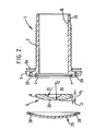
- the lens has a convex front face, a concave rear face and a negative focal length, that is to say the focal length of the lens is at a position to the rear of the front face of the lens, and the light source is located in very close proximity to the rear face of the lens.
- the lens has an external diameter of 49.5 mm, a thickness (T 1 ) of 4.5 mm, the curved front face has a depth (T 2 ) of 2.5 mm, the front face curve is of plus 8.87 diopters, the rear face curve is of minus 33 diopters, the whole of the rear face of the lens is frosted and the lens is made of crown glass with a refractive index of 1.523.
- the light source is so inserted in the rear end of the tube as to be relatively easily removable therefrom to replace or service the lighting source without breaking the seal of the tubular member in the wall of the vessel.
- Colour filter members may be provided to be mountable over the front face of the lens to colour the light emanating from the lighting unit.
- two colours or more are provided on a filter with the interface between the two colours being provided as a generally horizontal line and preferably with the dark colour or a colour at the top and a light colour or white below.
- an electrical earthing clamp may be provided on the tubular member at the rear of the position in which the wall of the vessel is located in use.
- the tubular member preferably has an outwardly extending flange adjacent its front end and a rearward portion of the tubular member has a screwthread on its outer diameter, a nut being provided to engage on the screwthreaded portion of the tubular member to pull the screwthreaded portion outwardly with respect to the wall of the vessel to press the flange against the inner face of the wall of the vessel with the interposition of a sealing gasket.
- a generally cylindrical recess is advantageously provided at the front end of the bore of the tubular member, which recess can receive the lens with the lens sealed in the recess by a flexible adhesive substance.
- a peripheral groove is provided in the wall of the recess and a peripheral groove is provided in the outer edge of the lens, the grooves and receiving the flexible adhesive substance and securing the lens in the recess.
- Bores may be provided in the front face of the flange of the tubular member, outwardly of the position at which the lens is located, to receive pegs extending from the colour filters and thereby secure the colour filters with respect to the tubular member.
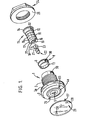
- a lighting unit comprises a tubular member 1 externally screwthreaded at 2 and having an outwardly extending flange 3 at its front end.
- the front face of the tubular member is recessed with a circular recess 4 to receive a lens 5, the lens 5 being potted into the recess 4 with a combined adhesive and sealant which penetrates into a peripheral groove 6 in the outer edge of the lens 5 and into a peripheral groove 7 in the recess 4. After the sealant has cured somewhat it remains flexible but loses the ability to be extruded and thus retains and seals the lens 5 in the recess 4.
- a bulb mounting member 11 is generally cylindrical, has a portion 12 which is a sliding fit in the bore 13 of the collar 8, has a collar 14 at its outer end and has its inner end 15 of somewhat smaller diameter than the portion 12 and perforated by perforations 16.
- the bulb mounting member 11 is formed of aluminium alloy and at its front end is formed with a flange 17 with two screwthreaded apertures 18 therein and with a central bore 19 with a circular recess 20 in the forward face.
- the recess 20 receives a mounting plate 21 of a bulb 22, the mounting plate 21 having recesses 23 at opposite sides thereof to enable the mounting plate to be engaged in the recess 20 with the heads of screws engaged in the screwthreaded apertures 18 passing through the cut-outs 23.
- the mounting plate 21, together with the bulb 22, can subsequently be rotated about its longitudinal axis to engage portions of the plate 21 beneath the edges of the screw heads and thereby secure the bulb 22 on the bulb mounting member 11.
- a nut 24 is provided to be engaged on the screwthread 2 of the tubular member 1, the nut 24 having a circular flange 25 at its forward face.
- the flange 3 of the tubular member 1 includes two bores 26 to receive plastics peg members 27 which project through apertures 28 in a filter member 29, preferably formed of a flexible plastics material.
- the threaded portion 2 of the tubular member 1 is engaged in an aperture in the wall of a vessel which is to contain liquid, the portion 2 being engaged in the aperture from the inside of the vessel, with a gasket being provided between the flange 3 and the wall of the vessel.
- the nut 24 is engaged on the screwthreads 2 and rotated so that the flange 25 engages the outer face of the wall of the vessel to clamp the tubular member 1 in the wall of the vessel and effect sealing by the gasket.
- the lens 5 will already have been potted into the front end of the tubular member 1 in the recess 4.
- the bulb 22 is mounted on the bulb mounting member 11, the collar 8 is engaged in the rear end of the tubular member 1 and the bulb mounting member is inserted into the collar 8 and pressed fully forward thereby to position the bulb 22 closely adjacent the rear face of the lens 5 and indeed to engage it within a recess 30 in the rear face of the lens 5.
- a screw (not shown) of electrically insulating material is then inserted through aligned radially extending apertures 31 in the tubular member 1 and the collar 8 and engaged in an aperture 32 in the bulb mounting member 11, which aperture 32 is screwthreaded. The screw secures the bulb mounting member 11 and collar 8 in position with respect to the tubular member 1. Wires extend from the the bulb 22 outwardly through the rear of the tubular member 1, the bulb 22 being a 55 watt quartz halogen automobile bulb designed to operate on a 12 volt supply.
- one of the filter members 29 of suitable colour can be engaged on the front end of the tubular member 1 by engaging the peg like members 27 in the bores 26.
- the maximum diameter of the flange 3 is preferably 75 mm, the diameter of the screwthreaded portion 2 is preferably 50 mm and the distance from the rear face of the flange 3 to the free end of the tubular member 1 is preferably approximatley 75 mm. Due to the very small diameter of the tubular member 1, compared with previously proposed lighting units, it is possible to mount the lighting unit in vessels having curved walls without causing undue sealing problems.
- the lens 5 preferably has an external diameter of 49.5 mm a thickness T 1 of 4.5 mm, the curved front face 33 has a depth T 2 of 2.5 mm, the front face curve 33 being of plus 8.87 diopters, the rear curve 30 being of minus 33 diopters and the whole of the rear face of the lens being frosted.
- the lens can be made of crown glass with a refractive index of 1.523 with the curvatures given above.
- flint glass for example the material Hilite sold by Corning Glass Co of the United States of America with a refractive index of 1.79 or the glass FX1 sold by Pilkington Glass Company Limited.
- the lens specified above can, when submerged in water, provide illumination over a cone of 172 angle.
- the bulb mounting member 11 with the perforation 16 therein provides some heat dissipation for the heat generated by the bulb 22 but the major part of such heat is required to be dissipated through the lens 5 and the flange 3 into the liquid.
- the lighting unit of the invention is that if the bulb 22 should fail it can be replaced without draining the liquid from the vessel and since the bulb mounting member can be simply withdrawn from the rear end of a tubular member 1, the bulb can be replaced by a relatively unskilled person.
Landscapes
- Engineering & Computer Science (AREA)
- General Engineering & Computer Science (AREA)
- Non-Portable Lighting Devices Or Systems Thereof (AREA)
- Securing Globes, Refractors, Reflectors Or The Like (AREA)
Applications Claiming Priority (2)
| Application Number | Priority Date | Filing Date | Title |
|---|---|---|---|
| GB8501278 | 1985-01-18 | ||
| GB858501278A GB8501278D0 (en) | 1985-01-18 | 1985-01-18 | Lighting unit for liquids |
Publications (1)
| Publication Number | Publication Date |
|---|---|
| EP0188366A2 true EP0188366A2 (de) | 1986-07-23 |
Family
ID=10573037
Family Applications (1)
| Application Number | Title | Priority Date | Filing Date |
|---|---|---|---|
| EP86300200A Withdrawn EP0188366A2 (de) | 1985-01-18 | 1986-01-14 | Leuchtvorrichtung für Flüssigkeiten |
Country Status (3)
| Country | Link |
|---|---|
| US (1) | US4644450A (de) |
| EP (1) | EP0188366A2 (de) |
| GB (1) | GB8501278D0 (de) |
Cited By (4)
| Publication number | Priority date | Publication date | Assignee | Title |
|---|---|---|---|---|
| EP0460269A1 (de) * | 1988-11-21 | 1991-12-11 | Hoyer, Ann, I. | Einbauvorrichtung einer Wasserlampe |
| EP1083384A1 (de) * | 1999-09-10 | 2001-03-14 | Certikin International Ltd | Halogenleuchteneinheit |
| US6398382B1 (en) * | 2000-06-12 | 2002-06-04 | Seh America, Inc. | Apparatus and method for indicating liquid level in a chemical tank |
| RU197224U1 (ru) * | 2020-02-05 | 2020-04-14 | Общество с ограниченной ответственностью фирма "Спецоснастка и металлоконструкции" | Устройство рассечения водяной струи в ламинарном фонтане |
Families Citing this family (7)
| Publication number | Priority date | Publication date | Assignee | Title |
|---|---|---|---|---|
| USD320862S (en) | 1989-04-07 | 1991-10-15 | American Standard Inc. | Recessed underwater light for bathtub |
| US7520628B1 (en) * | 2003-10-23 | 2009-04-21 | Sloanled, Inc. | High flux led lamp |
| GB2437975A (en) * | 2006-05-08 | 2007-11-14 | Bernard Cook | A Flush Fitting Shelf Light |
| USD633649S1 (en) | 2008-03-31 | 2011-03-01 | Cooper Technologies Company | LED light fixture |
| WO2012005596A1 (en) * | 2010-06-22 | 2012-01-12 | Fjordbad As | Lighting device |
| USD736722S1 (en) * | 2014-02-12 | 2015-08-18 | Ching-Hsiung Chu | Touch switch |
| GB201903457D0 (en) * | 2019-03-13 | 2019-04-24 | Boden Vincent | Airtight downlight installation |
Family Cites Families (4)
| Publication number | Priority date | Publication date | Assignee | Title |
|---|---|---|---|---|
| US2330935A (en) * | 1942-01-21 | 1943-10-05 | Holophane Co Inc | Combined building walls and lighting equipment |
| US2824217A (en) * | 1957-02-05 | 1958-02-18 | John J Karole | Electrical lighting fixture |
| US4433366A (en) * | 1982-09-30 | 1984-02-21 | Wade Charles E | Pool light mounting structure |
| US4574337A (en) * | 1984-02-10 | 1986-03-04 | Gty Industries | Underwater lights |
-
1985
- 1985-01-18 GB GB858501278A patent/GB8501278D0/en active Pending
-
1986
- 1986-01-14 EP EP86300200A patent/EP0188366A2/de not_active Withdrawn
- 1986-01-15 US US06/819,114 patent/US4644450A/en not_active Expired - Fee Related
Cited By (4)
| Publication number | Priority date | Publication date | Assignee | Title |
|---|---|---|---|---|
| EP0460269A1 (de) * | 1988-11-21 | 1991-12-11 | Hoyer, Ann, I. | Einbauvorrichtung einer Wasserlampe |
| EP1083384A1 (de) * | 1999-09-10 | 2001-03-14 | Certikin International Ltd | Halogenleuchteneinheit |
| US6398382B1 (en) * | 2000-06-12 | 2002-06-04 | Seh America, Inc. | Apparatus and method for indicating liquid level in a chemical tank |
| RU197224U1 (ru) * | 2020-02-05 | 2020-04-14 | Общество с ограниченной ответственностью фирма "Спецоснастка и металлоконструкции" | Устройство рассечения водяной струи в ламинарном фонтане |
Also Published As
| Publication number | Publication date |
|---|---|
| US4644450A (en) | 1987-02-17 |
| GB8501278D0 (en) | 1985-02-20 |
Similar Documents
| Publication | Publication Date | Title |
|---|---|---|
| US4450511A (en) | Submersible high intensity lamp | |
| US4644450A (en) | Lighting unit for liquids | |
| US5800041A (en) | Underwater light fitting | |
| US7044623B2 (en) | Thru-hull light | |
| GB2413840A (en) | Underwater lighting unit with cooling means | |
| US7458330B2 (en) | Two piece view port and light housing with integrated ballast and high intensity discharge lamp | |
| US4683523A (en) | Deep submersible light assembly | |
| US8632230B2 (en) | Deep submersible light with pressure compensation | |
| US7552693B2 (en) | Two piece view port and light housing with swivel light | |
| US5799124A (en) | Illuminating system and method for specialized and decorative lighting using liquid light guides | |
| US7520628B1 (en) | High flux led lamp | |
| US20100002435A1 (en) | Led light with a diffracting lens | |
| US5825954A (en) | Submersible fiber optics lens assembly | |
| US20080083360A1 (en) | Window housing for use with thru-hull fittings | |
| CN112664845B (zh) | 一种防眩目的led照明灯管 | |
| US6398397B1 (en) | Fiber optic pool lighting apparatus | |
| US4156894A (en) | Light fitting | |
| US3474243A (en) | Support assembly for underwater lamp | |
| CA1171828A (en) | Submersible high intensity lamp | |
| US8016463B2 (en) | Transom drain light | |
| CN216556974U (zh) | 透镜结构及照明灯具 | |
| JP4451711B2 (ja) | 水中照明装置 | |
| US20070137544A1 (en) | Two piece view port and light housing | |
| US3220327A (en) | Adapter lamp for use with underwater television cameras | |
| CN216521131U (zh) | 泳池灯 |
Legal Events
| Date | Code | Title | Description |
|---|---|---|---|
| PUAI | Public reference made under article 153(3) epc to a published international application that has entered the european phase |
Free format text: ORIGINAL CODE: 0009012 |
|
| AK | Designated contracting states |
Kind code of ref document: A2 Designated state(s): AT BE CH DE FR GB IT LI LU NL SE |
|
| STAA | Information on the status of an ep patent application or granted ep patent |
Free format text: STATUS: THE APPLICATION HAS BEEN WITHDRAWN |
|
| 18W | Application withdrawn |
Withdrawal date: 19880308 |
|
| RIN1 | Information on inventor provided before grant (corrected) |
Inventor name: HUNT, DAVID Inventor name: CAPLIN, ROGER WILLIAM GEORGE Inventor name: FRY, GERALD LESTER Inventor name: SOUTHERN, RODERIC GEORGE |