EP0188199B2 - Aircraft landing gear - Google Patents
Aircraft landing gear Download PDFInfo
- Publication number
- EP0188199B2 EP0188199B2 EP19860100073 EP86100073A EP0188199B2 EP 0188199 B2 EP0188199 B2 EP 0188199B2 EP 19860100073 EP19860100073 EP 19860100073 EP 86100073 A EP86100073 A EP 86100073A EP 0188199 B2 EP0188199 B2 EP 0188199B2
- Authority
- EP
- European Patent Office
- Prior art keywords
- aircraft
- sensor
- landing gear
- undercarriage
- hydraulic medium
- Prior art date
- Legal status (The legal status is an assumption and is not a legal conclusion. Google has not performed a legal analysis and makes no representation as to the accuracy of the status listed.)
- Expired - Lifetime
Links
- 230000033001 locomotion Effects 0.000 claims description 35
- 238000005096 rolling process Methods 0.000 claims description 11
- 230000001133 acceleration Effects 0.000 claims description 9
- 230000005484 gravity Effects 0.000 claims description 5
- 238000010521 absorption reaction Methods 0.000 claims 3
- 230000003534 oscillatory effect Effects 0.000 claims 2
- 230000002745 absorbent Effects 0.000 claims 1
- 239000002250 absorbent Substances 0.000 claims 1
- 238000013016 damping Methods 0.000 description 20
- 230000004044 response Effects 0.000 description 12
- 230000003068 static effect Effects 0.000 description 6
- 238000004364 calculation method Methods 0.000 description 3
- 230000006872 improvement Effects 0.000 description 3
- 230000008901 benefit Effects 0.000 description 2
- 230000000694 effects Effects 0.000 description 2
- 230000005284 excitation Effects 0.000 description 2
- 230000001105 regulatory effect Effects 0.000 description 2
- 239000000725 suspension Substances 0.000 description 2
- 244000059549 Borneo rubber Species 0.000 description 1
- 230000008859 change Effects 0.000 description 1
- 238000004590 computer program Methods 0.000 description 1
- 230000006378 damage Effects 0.000 description 1
- 238000010586 diagram Methods 0.000 description 1
- 239000013013 elastic material Substances 0.000 description 1
- 230000002349 favourable effect Effects 0.000 description 1
- 239000000446 fuel Substances 0.000 description 1
- 239000010720 hydraulic oil Substances 0.000 description 1
- 239000012528 membrane Substances 0.000 description 1
- 239000003921 oil Substances 0.000 description 1
- 230000010363 phase shift Effects 0.000 description 1
- 230000035939 shock Effects 0.000 description 1
- 238000005728 strengthening Methods 0.000 description 1
Images


Classifications
-
- B—PERFORMING OPERATIONS; TRANSPORTING
- B64—AIRCRAFT; AVIATION; COSMONAUTICS
- B64C—AEROPLANES; HELICOPTERS
- B64C25/00—Alighting gear
- B64C25/32—Alighting gear characterised by elements which contact the ground or similar surface
- B64C25/58—Arrangements or adaptations of shock-absorbers or springs
- B64C25/60—Oleo legs
-
- F—MECHANICAL ENGINEERING; LIGHTING; HEATING; WEAPONS; BLASTING
- F16—ENGINEERING ELEMENTS AND UNITS; GENERAL MEASURES FOR PRODUCING AND MAINTAINING EFFECTIVE FUNCTIONING OF MACHINES OR INSTALLATIONS; THERMAL INSULATION IN GENERAL
- F16F—SPRINGS; SHOCK-ABSORBERS; MEANS FOR DAMPING VIBRATION
- F16F15/00—Suppression of vibrations in systems; Means or arrangements for avoiding or reducing out-of-balance forces, e.g. due to motion
- F16F15/02—Suppression of vibrations of non-rotating, e.g. reciprocating systems; Suppression of vibrations of rotating systems by use of members not moving with the rotating systems
- F16F15/023—Suppression of vibrations of non-rotating, e.g. reciprocating systems; Suppression of vibrations of rotating systems by use of members not moving with the rotating systems using fluid means
- F16F15/027—Suppression of vibrations of non-rotating, e.g. reciprocating systems; Suppression of vibrations of rotating systems by use of members not moving with the rotating systems using fluid means comprising control arrangements
Definitions
- the invention relates to an aircraft landing gear with a resilient and damping cylinder arrangement, according to the preamble of claim 1.
- Such an aircraft landing gear is known from FR-A-2 386 427.
- the additional chamber is connected to the first work space, so that the air cushion in the second work space is only influenced by the throttle by the actuation of the servo valve.
- the invention is directed to an aircraft landing gear which is intended to enable the vibration movements of the aircraft to be reduced when taxiing on an even uneven roadway. Since fighter jets in particular also have to operate from makeshift lanes with corresponding bumps, considerable stresses occur in the takeoff and landing phases on the airframe and on the landing gear. U. can lead to structural destruction of the aircraft.
- the previously known aircraft landing gears have a cylinder arrangement, the two working spaces filled with hydraulic medium are connected to one another via a throttle.
- the first work space is connected to the unsprung mass of the landing gear, while the second work space is provided on the side of the airframe.
- the work area which is arranged on the side of the airframe, also includes an air cushion, so that the spring and damping functions of the landing gear result overall.
- These known aircraft undercarriages are designed exclusively according to the loads occurring during the landing impact, i.e. H. it is assumed that the landing shock represents the greatest load and that the forces can be absorbed anyway when rolling on a comparatively flat loading runway. The problem in connection with the dynamic structure-like behavior of the aircraft when taxiing on uneven road surfaces is therefore not given special attention.
- the invention has for its object to develop an aircraft landing gear of the type described in such a way that the dynamic loads on the landing gear and on the airframe are reduced when taxiing even on uneven road surfaces.
- the undercarriage must of course also be suitable for absorbing the load when landing.
- an actively controlled aircraft undercarriage is created, which makes it possible to reduce the vibration movements and structural loads on the aircraft when taxiing on the runway by reducing the speed of the aircraft movements.
- the air cushion contained in the undercarriage is compressed or expanded.
- forces can be generated in the undercarriage which act as damping forces in the event of a phase shift of 90 ° relative to the undercarriage movement - i.e. in phase with the speed of the oscillating movement - and consequently reduce the oscillating movements.
- the undercarriage must therefore work in a control loop.
- the invention can be used on the entire landing gear of an aircraft, but can also be used on any individual landing gear unit. It is therefore also possible to use the invention in a very targeted manner for special movements: by returning the vertical speed of the center of gravity of the aircraft - via a compensation network to the servo valves of the cylinder arrangement of the main landing gear, the vertical vibration movement of the rolling aircraft can be damped.
- the pitching movement of the rolling vehicle can be dampened by feeding the pitching speed of the aircraft back via a compensation network to the servo valve of the nose landing gear.
- the roll movement of the aircraft that is rolling can be dampened dynamically.
- the newly developed aircraft landing gear has similar damping properties when landing like a conventional aircraft chassis.
- this active regulation With the introduction of this active regulation, the vibrational movements of the aircraft and thus the structural loads when taxiing can be reduced even on uneven surfaces without increasing the structural loads during the landing impact compared to a conventional landing gear. It is also advantageous that with this active regulation, in addition to the rigid body movements of the aircraft, higher-frequency vibratory movements of the elastic aircraft are reduced when taxiing on an uneven road surface.
- the additional chamber can also be structurally combined with the one working space of the cylinder arrangement. This has the advantage that the overall height of the aircraft landing gear does not increase compared to known landing gear. The same damping effect can be achieved as with a separate arrangement of the additional chamber. Here, too, it is necessary to separate the air cushion from the additional chamber by means of a movable wall.
- the compensation network of the control loop between the sensor and the additional chamber can, depending on the sensor design, have an integrator, in particular to integrate the accelerations recorded by a sensor designed as an accelerometer.
- the movable wall can be suitably as a membrane made of an elastic material, for. B. rubber.
- An additional control loop with pressure transmitter and PID controller can be provided to determine the stationary working point, which sets the pressure in the additional chamber. Static control of the chassis is thus possible.
- the pressure in the additional chamber is used as a static control variable.
- sensors - in particular acceleration sensors - can also be arranged distributed on the aircraft, the signals of which, after being superimposed, are fed to the individual units of the landing gear.
- the signals of which, after being superimposed, are fed to the individual units of the landing gear.
- the electrical signals from the sensors are correspondingly superimposed and fed via an electronic compensation network to the electrohydraulic servo valves of the individual units of the chassis as a manipulated variable.
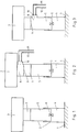
- a conventional chassis is shown schematically with the essential parts in the present context.
- the landing gear 2 On the runway 1, the landing gear 2 is shown with the aircraft cell 3, which is symbolically represented as the aircraft mass.
- a cylinder arrangement with two working spaces 4 and 5 is provided in the manner shown, which are connected to one another via a throttle 6. Both work rooms 4 and 5 are filled with hydraulic medium.
- An air cushion 7 is located above and enclosed in the work space 5.
- the known undercarriages are constructed according to this principle.
- FIG. 2 shows a first embodiment of the invention, similarly schematized as FIG. 1.
- an additional chamber 8 is provided, which is operatively connected to the air cushion 7 of the working space 5 via a movable wall 9.
- the additional chamber 8 is connected via a servo valve 10 to a pressure source for hydraulic medium, not shown.
- a supply line 11 and a discharge line 12 are provided, both of which lead to the pressure source.
- Fig. 3 illustrates an alternative embodiment form, in which the additional chamber 8 and the work space 5 are structurally combined. This design has the advantage of a lower chassis height.
- a sensor 13 is attached as an acceleration sensor, which emits the electrical signal X , which reaches a integrator via a line 14, which is connected to a compensation network 17 via a line 16.
- Line 16 carries the signal x.
- a line 18 connects the compensation network 17 to the electrohydraulic servo valve 10.
- FIGS. 4 to 6 the functional principle and the structure of the control system are exemplified for the case of a one-mass oscillator.
- the sensor 13 designed as an acceleration sensor, the acceleration of the mass that loads the chassis is determined.
- the integrated acceleration signal which is in phase with the speed of movement of the mass, is fed to an electronic compensation network 17. There it is amplified and filtered if necessary.
- the electro-hydraulic servo valve 10 is controlled with the electrical output signal of the compensation network. This valve regulates the inflow and outflow of the hydraulic medium into the additional chamber 8 of the chassis. This flow of the hydraulic medium in turn causes the air cushion 7 enclosed in the chassis to be compressed or expanded, as a result of which the damping forces are generated.
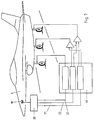
- Fig. 7 clearly shows the function of three controls, namely the return of the vertical speed, the return of the rolling speed and the return of the pitching speed.
- the airframe 3 has an inertial platform 19 which is connected to an on-board computer 20. From this lead a line 21 for the vertical speed of the center of gravity, a line 22 for the rolling speed and a line 23 for the pitching speed to the compensation network 17 and from there in the manner shown to the individual units of the overall chassis.
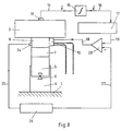
- Fig. 8 illustrates the additional control loop for the static control of the vehicle.
- a pressure transmitter 24 is provided on the additional chamber 8, from which a line 25 leads to a PID controller 26, from which a line 27 leads to a subtraction element 28, which is switched on in line 18, which connects the compensation network 17 with the connects electro-hydraulic servo valve.
- the pressure P in the additional chamber can be used as a static control variable to determine the stationary working point, that is to say to achieve the static control of the undercarriage.
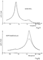
- 9 to 16 each show associated and assigned diagrams of the amplitude of the various movements over frequency.
- FIGS. 9 and 10 show calculation results in the event that only the control loop acting on the main running gear for damping the vertical movement (FIG. 7) is closed (i.e. active).
- the solid line shows the unregulated behavior, the dashed line the regulated behavior.
- the Nyquist locus for the open control loop shown in FIG. 11 indicates the good stability of the closed control loop; the point (-1.0, i 0) is not enclosed.
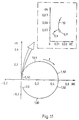
- FIG. 12 and 13 show calculation results in the event that only the control loop acting on the nose gear for damping the pitching movement is closed (FIG. 7).
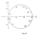
- the locus for the open control loop shown in FIG. 14 illustrates the good stability of the closed control loop.
Landscapes
- Engineering & Computer Science (AREA)
- Aviation & Aerospace Engineering (AREA)
- General Engineering & Computer Science (AREA)
- Mechanical Engineering (AREA)
- Physics & Mathematics (AREA)
- Acoustics & Sound (AREA)
- Vibration Prevention Devices (AREA)
Description
Die Erfindung bezieht sich auf ein Flugzeugfahrwerk mit einer federnden und dämpfenden Zylinderanordnung, gemäß dem Oberbegriff von Anspruch 1. Ein derartiges Flugzeugfahrwerk ist durch die FR-A-2 386 427 bekannt.The invention relates to an aircraft landing gear with a resilient and damping cylinder arrangement, according to the preamble of
Bei diesem Flugzeugfahrwerk ist die Zusatzkammer mit dem ersten Arbeitsraum verbunden, so daß das Luftpolster in dem zweiten Arbeitsraum durch die Betätigung des Servoventils nur über die Drossel beeinflußt wird.In this aircraft landing gear, the additional chamber is connected to the first work space, so that the air cushion in the second work space is only influenced by the throttle by the actuation of the servo valve.
Die Erfindung ist auf ein Flugzeugfahrwerk gerichtet, welches die Abminderung der Schwingungsbewegungen des Flugzeuges beim Rollen auf einer auch unebenen Fahrbahn ermöglichen soll. Da insbes. Kampfflugzeuge auch von nur notdürftig angelegten Fahrbahnen mit entsprechenden Unebenheiten aus operieren müssen, entstehen in den Start-und Landephasen an der Flugzeugzelle und am Fahrwerkerhebliche Belastungen, die u. U. zurstrukturellen Zerstörung des Flugzeuges führen können.The invention is directed to an aircraft landing gear which is intended to enable the vibration movements of the aircraft to be reduced when taxiing on an even uneven roadway. Since fighter jets in particular also have to operate from makeshift lanes with corresponding bumps, considerable stresses occur in the takeoff and landing phases on the airframe and on the landing gear. U. can lead to structural destruction of the aircraft.
Die bisher bekannten Flugzeugfahrwerke weisen eine Zylinderanordnung auf, deren beide mit Hydraulikmedium gefüllte Arbeitsräume über eine Drossel miteinander verbunden sind.The previously known aircraft landing gears have a cylinder arrangement, the two working spaces filled with hydraulic medium are connected to one another via a throttle.
Der erste Arbeitsraum ist mit der ungefederten Masse des Fahrwerks verbunden, während der zweite Arbeitsraum auf der Seite der Flugzeugzelle vorgesehen ist.The first work space is connected to the unsprung mass of the landing gear, while the second work space is provided on the side of the airframe.
Der Arbeitsraum, der auf der Seite der Flugzeugzelle angeordnet ist, schließt gleichzeitig ein Luftpolster ein, so daß sich insgesamt die federnde und die dämpfende Funktion des Fahrwerks ergibt. Diese bekannten Flugzeugfahrwerke werden heute ausschließlich nach den beim Landestoß auftretenden Belastungen ausgelegt, d. h. man geht davon aus, daß der Landestoß die größte Belastung darstellt und damit die Kräfte beim Rollen auf einer vergleichsweise ebenen Ladepiste ohnehin aufgenommen werden können. Der Problematik im Zusammenhang mit dem dynamischen struckturellen Verhalten des Flugzeugs beim Rollen auf unebener Fahrbahn wird somit keine gesonderte Beachtung geschenkt.The work area, which is arranged on the side of the airframe, also includes an air cushion, so that the spring and damping functions of the landing gear result overall. These known aircraft undercarriages are designed exclusively according to the loads occurring during the landing impact, i.e. H. it is assumed that the landing shock represents the greatest load and that the forces can be absorbed anyway when rolling on a comparatively flat loading runway. The problem in connection with the dynamic structure-like behavior of the aircraft when taxiing on uneven road surfaces is therefore not given special attention.
Es ist natürlich möglich, Fahrwerke verstärkt auszubilden, also entsprechend den beim Landestoß auftretenden Kräften so zu dimensionieren, daß dabei höhere Belastungen aufgenommen werden können. Eine soche Verstärkung des Fahrwerks hat jedoch den Nachteil, daß damit immer auch eine Erhöhung des Strukturgewichts verbunden ist. Dies wirkt sich negativ auf die Flugleistungen und insbesondere den Treibstoffbedarf des Flugzeugs aus. Andererseits ist es auch möglich, den mechanischen Aufbau des Fahrwerks derart zu ändern, daß das Fahrwerk bessere Dämpfungs- und/oder Federungseigenschaften aufweist. Solchen rein mechanischen Konstruktionsänderungen am Fahrwerk zur Dämpfungserhöhung sind jedoch Grenzen gesetz. Auch wenn sich eine Erhöhung der Fahrwerkdämpfung günstig auf die dynamischen strukturellen Belastungen beim Rollen auf unebener Fahrbahn auswirkt, so können dadurch jedoch unzulässig hohe Belastungen beim Landestoß auftreten.It is, of course, possible to increase the design of landing gears, that is to say dimension them in accordance with the forces occurring during the landing impact so that higher loads can be absorbed. Such a strengthening of the undercarriage has the disadvantage, however, that it always involves an increase in the structural weight. This has a negative impact on flight performance and, in particular, the fuel requirements of the aircraft. On the other hand, it is also possible to change the mechanical structure of the undercarriage in such a way that the undercarriage has better damping and / or suspension properties. However, there are limits to such purely mechanical design changes to the chassis to increase damping. Even if an increase in the suspension damping has a favorable effect on the dynamic structural loads when rolling on uneven road surfaces, this can result in impermissibly high loads on the landing impact.
Der Erfindung liegt die Aufgabe zugrunde, ein Flugzeugfahrwerk der eingangs beschriebenen Art derart weiterzubilden, daß die dynamischen Belastungen am Fahrwerk und an der Flugzeugzelle beim Rollen auch auf unebener Fahrbahn vermindert werden. Das Fahrwerk muß darüberhinaus natürlich geeignet sein, die Belastung beim Landestoß auch aufzunehmen.The invention has for its object to develop an aircraft landing gear of the type described in such a way that the dynamic loads on the landing gear and on the airframe are reduced when taxiing even on uneven road surfaces. The undercarriage must of course also be suitable for absorbing the load when landing.
Erfindungsgemäß wird dies durch die im Anspruch 1 angegebenen Merkmale erreicht.According to the invention this is achieved by the features specified in
Damit wird im Gegensatz zu den bisher bekannten passiven Fahrwerken ein aktiv geregeltes Flugzeugfahrwerk geschaffen, welches es ermöglicht, durch Rückführung der Geschwindigkeit der Flugzeugbewegungen, die Schwingungsbewegungen und strukturellen Belastungen der Flugzeuges beim Rollen auf der Landebahn zu vermindern. Durch das Zuführen oder Ablassen von Hydraulikmedium in die Zusatzkammer wird das im Fahrwerk enthaltene Luftpolster komprimiert oder expandiert. Dadurch lassen sich im Fahrwerk Kräfte erzeugen, die im Falle einer zeitlichen Phasenverschiebung von 90° relativ zur Fahrwerksbewegung - also in Phase mit der Geschwindigkeit der Schwingungsbewegung - als Dämpfungskräfte wirken und demzufolge die Schwingungsbewegungen mindern. Zur gezielten Erzeugung dieser Dämpfungskräfte muß somit das Fahrwerk in einem Regelkreis arbeiten. Hierzu gehören ein oder mehrere Sensoren, die entweder die Geschwindigkeit des Flugzeuges in den verschiedenen Bewegungsrichtungen oder aber die Beschleuniung des Flugzeuges messen. Die Erfindung läßt sich an dem Gesamtfahrwerk eines Flugzeuges einsetzen, kann aber auch gezieltanjedereinzelnen Fahrwerkseinheit benutzt werden. So ist es auch möglich, die Erfindung ganz gezielt für spezielle Bewegungen einzusetzen: Durch Rückführung der Vertikalgeschwindigkeit des Flugzeugschwerpunktes - über ein Kompensationsnetzwerk auf die Servoventile der Zylinderanordnung des Hauptfahrwerkes kann die Vertikalschwingungbewegung des rollenden Flugzeuges gedämpft werden. Durch Rückführung der Nickgeschwindigkeit des Flugzeuges - über ein Kompensationsnetzwerk - auf das Servoventil des Bugfahrwerks kann die Nickbewegung des rollenden Fahrzeuges gedämpft werden. Durch Rückführung der Rollgeschwindigkeit des Flugzeuges - über ein Kompensationsnetzwerk - auf die Servoventile der Zylinder des Hauptfahrwerks kann die Rollbewegung des rollenden Flugzeuges dynamisch gedämpft werden. Das neu entwickelte Flugzeugfahrwerk weist beim Landestoß ähnliche Dämpfungseigenschaften wie ein konventionelles Flugzeugfahrwerf auf. Durch die Einführung dieser aktiven Regelung können die Schwingungsbewegungen des Flugzeuges und damit die strukturellen Belastungen beim Rollen auch auf unebener Fahrbahn gemindert werden, ohne die strukturellen Belastungen beim Landestoß im Vergleich zu einem konventionellen Fahrwerk - zu erhöhen. Weiterhin ist vorteilhaft, daß mit dieser aktiven Regelung neben den Starrkörperbewegungen des Flugzeuges auch höherfrequente Schwingungsbewegungen des elastischen Flugzeuges beim Rollen auf unebener Fahrbahn gemindert werden.In contrast to the previously known passive undercarriages, an actively controlled aircraft undercarriage is created, which makes it possible to reduce the vibration movements and structural loads on the aircraft when taxiing on the runway by reducing the speed of the aircraft movements. By feeding or draining hydraulic medium into the additional chamber, the air cushion contained in the undercarriage is compressed or expanded. In this way, forces can be generated in the undercarriage which act as damping forces in the event of a phase shift of 90 ° relative to the undercarriage movement - i.e. in phase with the speed of the oscillating movement - and consequently reduce the oscillating movements. For the targeted generation of these damping forces, the undercarriage must therefore work in a control loop. This includes one or more sensors that either measure the speed of the aircraft in the various directions of movement or the acceleration of the aircraft. The invention can be used on the entire landing gear of an aircraft, but can also be used on any individual landing gear unit. It is therefore also possible to use the invention in a very targeted manner for special movements: by returning the vertical speed of the center of gravity of the aircraft - via a compensation network to the servo valves of the cylinder arrangement of the main landing gear, the vertical vibration movement of the rolling aircraft can be damped. The pitching movement of the rolling vehicle can be dampened by feeding the pitching speed of the aircraft back via a compensation network to the servo valve of the nose landing gear. By returning the aircraft's roll speed - via a compensation network - to the servo valves of the cylinders of the main landing gear, the roll movement of the aircraft that is rolling can be dampened dynamically. The newly developed aircraft landing gear has similar damping properties when landing like a conventional aircraft chassis. With the introduction of this active regulation, the vibrational movements of the aircraft and thus the structural loads when taxiing can be reduced even on uneven surfaces without increasing the structural loads during the landing impact compared to a conventional landing gear. It is also advantageous that with this active regulation, in addition to the rigid body movements of the aircraft, higher-frequency vibratory movements of the elastic aircraft are reduced when taxiing on an uneven road surface.
Die Zusatzkammer kann auch mit dem einen Arbeitsraum der Zylinderanordnung baulich vereinigt sein. Dies hat den Vorteil, daß sich die Bauhöhe des Flugzeugfahrwerks gegenüber bekannten Fahrwerken nicht erhöht. Damit kann eine gleiche dämpfende Wirkung wie bei getrennter Anordnung der Zusatzkammer erzielt werden. Auch hierbei ist es erfordelich, das Luftpolster von der zusatzkammer durch eine bewegliche Wand zu trennen.The additional chamber can also be structurally combined with the one working space of the cylinder arrangement. This has the advantage that the overall height of the aircraft landing gear does not increase compared to known landing gear. The same damping effect can be achieved as with a separate arrangement of the additional chamber. Here, too, it is necessary to separate the air cushion from the additional chamber by means of a movable wall.
Das Kompensationsnetzwerk des Regelkreises zwischen dem Sensor und derZusatzkammerkannje nach Sensorbauart einen Integrator aufweisen, um insbes. die von einem als Beschleunigungsnehmer ausgebildeten Sensor aufgenommenen Beschleunigungen zu intergrieren. Die bewegliche Wand kann zweckmäßig als Membran aus einem elastischen Werkstoff, z. B. Gummi, ausgebildet sein.The compensation network of the control loop between the sensor and the additional chamber can, depending on the sensor design, have an integrator, in particular to integrate the accelerations recorded by a sensor designed as an accelerometer. The movable wall can be suitably as a membrane made of an elastic material, for. B. rubber.
Für die Festlegung des stationären Arbeitspunktes kann eine zusätzliche Regelschleite mit Druckgeber und PID- Regler vorgesehen sein, die den Druck in der Zusatzkammer festlegt. Damit ist die statische Regelung des Fahrwerks möglich. Der Druck in der Zusatzkammer wird als statische Regelgröße benutzt.An additional control loop with pressure transmitter and PID controller can be provided to determine the stationary working point, which sets the pressure in the additional chamber. Static control of the chassis is thus possible. The pressure in the additional chamber is used as a static control variable.
Es können auch mehrere Sensoren - insbes. Beschleunigungsaufnehmer - auf dem Flugzeug verteilt angeordnet sein, deren Signale nach Überlagerung den einzelnen Einheiten des Fahrwerkes zugeführt werden. Mit einer solchen aktiven Regelung können somit nicht nur die Starrkörperfreiheitsgrade (Vertikalbewegung, Nicken, Rollen) des auf der Landebahn rollenden Fahrzeuges gedämpft werden. Es is auch möglich, sehr gezielt auf höherfrequente Eigenschwingungsformen des elastischen Flugzeuges dämpfend einzuwirken. Die elektrischen Signale der Sensoren werden dabei entsprechen überlagert und überein elektronisches Kompensationsnetzwerk den elektrohydraulischen Servoventilen der einzelnen Einheiten des Fahrwerks als Stellgröße zugeführt.Several sensors - in particular acceleration sensors - can also be arranged distributed on the aircraft, the signals of which, after being superimposed, are fed to the individual units of the landing gear. With such an active control, not only the rigid body degrees of freedom (vertical movement, pitching, rolling) of the vehicle rolling on the runway can be damped. It is also possible to have a very specific damping effect on higher-frequency natural vibration forms of the elastic aircraft. The electrical signals from the sensors are correspondingly superimposed and fed via an electronic compensation network to the electrohydraulic servo valves of the individual units of the chassis as a manipulated variable.
Die Erfindung wird anhand derZeichnungen weiter verdeutlicht und beschrieben. Es zeigt:
- Fig. 1 die schematische Darstellung der wesentlichen Teile eines passiven Flugzeugfahrwerks gemäß dem Stand der Technik,
- Fig. 2 die schematische Darstellung des erfindungsgemäßen aktiv geregelten Flugzeugfahrwerks in einer ersten Ausführungsform,
- Fig. 3 die schematische Darstellung des erfindungsgemäßen aktiv geregelten Flugzeugfahrwerks in einer zweiten Ausführungsform,
- Fig. 4 die Darstellung des Funktionsprinzips des aktiv geregelten Flugzeugfahrwerks,
- Fig. 5 die Darstellung der Kräfte zwischen Fahrwerk und Flugzeugzelle,
- Fig. 6 weitere Einzelheiten des Regelkreises des Flugzeugfahrwerks,
- Fig. 7 die Verdeutlichung verschiedener Regelkreise zur aktiven Dämpfung der Flugzeugbewegungen,
- Fig. 8 die Weiterbildung des aktiv geregelten Fahrzeugs mit zusätzlicher statischer Regelung,
- Fig. 9 den Frequenzgang des Nickwinkels,
- Fig. 10 den Frequenzgang der Vertikalbewegung der dynamischen Antwort des Flugzeuges bei offenem und geschlossenem Regelkreis,
- Fig. 11 die Nyquist-Orstkurve für den offenen Regelkreis zum Dämpfen der Vertikalbewegung,
- Fig. 12 den Frequenzgang des Nickwinkels,
- Fig. 13 den Frequenzgang der Vertikalbewegung der dynamischen Antwort des Flugzeuges bei offenem und geschlossenem Regelkreis bzgl. der Dämpfung der Nickbewegung,
- Fig. 14 die Nyquist-Ortskurve fürden offenen Regelkreis zum Dämpfen der Nickbewegung,
- Fig. 15 den Frequenzgang des Nickwinkels und
- Fig. 16 den Frequenzgang der Vertikalbewegung der dynamischen Antwort des Flugzeuges bei offenen und geschlossenen Regelkreisen hinsichtlich der Dämpfung der Vertikalund der Nickbewegung.
- 1 is a schematic representation of the essential parts of a passive aircraft landing gear according to the prior art,
- 2 shows the schematic representation of the actively controlled aircraft landing gear according to the invention in a first embodiment,
- 3 shows the schematic representation of the actively controlled aircraft landing gear according to the invention in a second embodiment,
- 4 shows the functional principle of the actively regulated aircraft landing gear,
- 5 shows the forces between the landing gear and the airframe,
- 6 further details of the control loop of the aircraft landing gear,
- 7 shows various control loops for active damping of aircraft movements,
- 8 shows the further development of the actively controlled vehicle with additional static control,
- 9 shows the frequency response of the pitch angle,
- 10 shows the frequency response of the vertical movement of the dynamic response of the aircraft with the control loop open and closed,
- 11 shows the Nyquist orst curve for the open control loop for damping the vertical movement,
- 12 shows the frequency response of the pitch angle,
- 13 shows the frequency response of the vertical movement of the dynamic response of the aircraft with an open and closed control loop with regard to the damping of the pitching movement,
- 14 shows the Nyquist locus for the open control loop to dampen the pitching movement.
- 15 shows the frequency response of the pitch angle and
- 16 shows the frequency response of the vertical movement of the dynamic response of the aircraft with open and closed control loops with regard to the damping of the vertical and pitching movements.
In Fig. 1 ist ein konventionelles Fahrwerk schematisch mit den im vorliegenden Zusammenhang wesentlichen Teilen dargestellt. Auf der Landebahn 1 ist das Fahrwerk 2 mit der Flugzeugszelle 3 dargestellt, die als Flugzeugmasse symbolisch wiedergegeben ist. Es ist eine Zylinderanordnung mit zwei Arbeitsräumen 4 und 5 in der dargestellten Weise vorgesehen, die miteinander über eine Drossel 6 in Verbindung stehen. Beide Arbeiträume 4 und 5 sind mit Hydraulikmedium gefüllt. Oberhalb des Arbeitsraumes 5 und in diesen eingeschlossen befindet sich ein Luftpolster 7. Nach diesem Prinzip sind die bekannten Fahrwerke aufgebaut.In Fig. 1, a conventional chassis is shown schematically with the essential parts in the present context. On the
Fig. 2 zeigt eine erste Ausführungsform der Erfindung, ähnlichschematisiert wie Fig. 1. Zusätzlich ist eine Zusatzkammer 8 vorgesehen, die über eine bewegliche Wand 9 mit dem Luftpolster 7 des Arbeitsraumes 5 in Wirkverbindung steht. Andererseits ist die Zusatzkammer 8 über ein Servoventil 10 an einer nicht dargestellten Druckquelle für Hydraulikmekium verbunden. Es ist eine Zuleitung 11 und eine Ableitung 12 vorgesehen, die beide zu der Druckquelle führen.FIG. 2 shows a first embodiment of the invention, similarly schematized as FIG. 1. In addition, an
Fig. 3 verdeutlicht eine alternative Ausführungsform, bei der die Zusatzkammer 8 und der Arbeitsraum 5 baulich vereinigt sind. Diese Bauart hat den Vorteil einer geringeren Höhe des Fahrwerks.Fig. 3 illustrates an alternative embodiment form, in which the
Die Fig. 4 und 5 verdeutlichen das Funktionsprinzip. Die Masse m der Flugzeugzelle 3 bewegt sich in x -Richtung, also federt gleichsam auf dem Fahrwerk ein. Schematisch ist die Dämpfungskonstante d des passiven Fahrwerks und die Dämpfungskonstante (d + c a) des aktiven Fahrwerks verdeutlicht, wobei ein Faktor a benutzt ist, der sich aus der Gleichung![]()
![]()
![]()
![]()
![]()
![]()
![]()
![]()
![]()
![]()
In Fig. 6 sind weitere Einzelheiten dargestellt. Im Bereich der Flugzeugzelle 3 ist ein Sensor 13 als Beschleunigungsaufnehmer angebracht, der das elektrische Signal X abgibt, welches über eine Leitung 14 zu einem Integrator gelangt, der über eine Leitung 16 mit einem Kompensationsnetzwerk 17 verbunden ist. Die Leitung 16 führt das Signal x. Eine Leitung 18 verbindet das Kompensationsnetwerk 17 mit dem elektrohydraulischen Servoventil 10. In den Fig. 4 bis 6 ist für den Fall eines Ein-Massen-Schwingers das Funktionsprinzip und der Aufbau des Reglersystems beispielhaft dargestellt. Mit Hilfe des als Beschleunigungsaufnehmer ausgebildeten Sensors 13 wird die Beschleunigung der Masse, die das Fahrwerk belastet, ermittelt. Das integrierte Beschleunigungssignal, welches in Phase mit der Bewegungsgeschwindigkeit der Masse ist, wird einem elektronischen Kompensationsnetzwerk 17 zugeführt. Dort wird es verstärkt und falls erforderlich gefiltert. Mit dem elektrischen Ausgangssignal des Kompensationsnetzwerkes wird das elektrohydraulische Servoventil 10 angesteuert. Dieses Ventil reguliert den Zu- und Abfluß des Hydraulikmediums in die Zusatzkammer 8 des Fahrwerks. Dieser Strom des hydraulischen Mediums wiederum bewirkt das Komprimieren oder Expandieren des im Fahrwerk eingeschlossenen Luftpolsters 7, wodurch die Dämpfungskräfte erzeugt werden.6 shows further details. In the area of the
Fig. 7 zeigt übersichtlich die Funktion von drei Regelungen, nämlich der Rückführung der Vertikalgeschwindigkeit, der Rückführung der Rollgeschwindigkeit und der Rückführung der Nickgeschwindigkeit. Die Flugzeugzelle 3 weist eine Trägheitsplattform 19 auf, die in Verbindung mit einem Bordrechner 20 steht. Von diesem führen eine Leitung 21 für die Vertikalgeschwindigkeit des Schwerpunktes, eine Leitung 22 für die Rollgeschwindigkeit und eine Leitung 23 für die Nickgeschwindigkeit zu dem Kompensationsnetzwerk 17 und von dort in der dargestellten Weise zu den einzelnen Einheiten des Gesamtfahrwerks.Fig. 7 clearly shows the function of three controls, namely the return of the vertical speed, the return of the rolling speed and the return of the pitching speed. The
Fig. 8 verdeutlicht die zusätzliche Regelschleife für die statische Regelung des Fahrzeuges. Es ist hier ein Druckgeber 24 an der Zusatzkammer 8 vorgesehen, von dem eine Leitung 25 zu einem PID-Regler 26 führt, von welchem eine Leitung 27 zu einem Subtraktionsglied 28 führt, welches in die Leitung 18 eingeschaltet ist, die das Konpensationsnetzwerk 17 mit dem elektrohydraulischen Servoventil verbindet. Auf diese Art und Weise kann der Druck P in der Zusatzkammer als statische Regelgröße dazu benutzt werden, um den stationären Arbeitspunkt festzulegen, also die statische Regelung des Fahrwerks zu erreichen. Die Fig. 9 bis 16 zeigen jeweils einander zugehörige und zugeordnete Diagramme der Amplitude der verschiedenen Bewegungen über der Frequenz. Mit Hilfe eines Rechenprogramms wurde - für ein idealisiertes mathematisches Flugzeugmodell die dynamische Antwort auf eine äußere harmonische Erregung des Fahrwerks ermittelt. Die in Form von Frequenzgangkurven aufgetragenen Ergebnisse zeigen, daß - jeweils für eine gleiche Anregung des Fahrwerks - die Schwingungsbewegungen des Flugzeugs mit aktivem Fahrwerk erheblich kleiner als im Falle des Flugzeugs min konventionellem Fahrwerk sind.Fig. 8 illustrates the additional control loop for the static control of the vehicle. A
Die Fig. 9 und 10 zeigen Rechenergebnisse für den Fall, daß nur der auf die Hauptfahrwerke wirkende Regelkreis zur Dämpfung der Vertikalbewegung (Fig. 7) geschlossen (d. h. aktiv) ist. Die durchgezogene Linie zeigt das ungeregelte, die gestrichelte Linie das geregelte Verhalten. Die in Fig. 11 dargestellte Nyquist-Ortskurve für den offenen Regelkreis weist auf die gute Stabilität des geschlossenen Regelkreises hin; der Punkt (-1.0, i 0) wird nicht umschlossen.FIGS. 9 and 10 show calculation results in the event that only the control loop acting on the main running gear for damping the vertical movement (FIG. 7) is closed (i.e. active). The solid line shows the unregulated behavior, the dashed line the regulated behavior. The Nyquist locus for the open control loop shown in FIG. 11 indicates the good stability of the closed control loop; the point (-1.0, i 0) is not enclosed.
Die Fig. 12 und 13 zeigen Rechenergebnisse für den Fall, daß nur der auf das Bugfahrwerk wirkende Regelkreis zur Dämpfung der Nickbewegung geschlossen ist (Fig. 7). Die in Fig. 14 dargestellte Ortskurve für den offenen Regelkreis verdeutlicht die gute Stabilität des geschlossenen Regelkreises.12 and 13 show calculation results in the event that only the control loop acting on the nose gear for damping the pitching movement is closed (FIG. 7). The locus for the open control loop shown in FIG. 14 illustrates the good stability of the closed control loop.
Die Fig. 15 und 16 zeigen Rechenergebnisse für den Fall, daß beide Regelkreise - zum Dämpfen der Vertikalbewegung und der Nickbewegung - geschlossen sind. Die in diese Figur aufgetragenen Frequenzgangkurven zeigen - welch enorme Verbesserungen im Schwingungsverhalten durch die Integration eines aktiven Fahrwerks erzielt werden können.15 and 16 show calculation results in the event that both control loops - for damping the vertical movement and the pitching movement - are closed. The frequency response curves plotted in this figure show what enormous improvements in vibration behavior can be achieved by integrating an active chassis.
Die hier aufgeführten Verbesserungen sind typisch für den Fall von Kampfflugzeugen. Der zur Regelung erforderliche Bedarf an Hochdruckhydrauliköl (ca. 301/min) kann während der Rollphase des Flugzeugs problemlos von den flugzeugeigenen Hydraulikpumpen geliefert werden. Für den Fall, daß ein höherer Ölstrom zur Verfügung steht, ist eine weitere Verbesserung der aufgeführten Ergebnisse möglich.The improvements listed here are great pisch in the case of fighter planes. The need for high-pressure hydraulic oil required for control (approx. 301 / min) can easily be supplied by the aircraft's own hydraulic pumps during the aircraft's roll phase. In the event that a higher oil flow is available, a further improvement of the results listed is possible.
- 1 = Landebahn1 = runway
- 2 = Fahrwerk2 = undercarriage
- 3 = Flugzeugzelle3 = airframe
- 4 = Arbeitsraum4 = work space
- 5 = Arbeitsraum5 = work space
- 6 = Drossel6 = throttle
- 7 = Luftpolster7 = air cushion
- 8 = Zusatzkammer8 = additional chamber
- 9 = bewegliche Wand9 = movable wall
- 10 = Servoventil10 = servo valve
- 11 = Zuleitung11 = supply line
- 12 = Ableitung12 = derivative
- 13 = Sensor13 = sensor
- 14 = Leitung14 = line
- 15 = Integrator15 = integrator
- 16 = Leitung16 = line
- 17 = Kompensationsnetzwerk17 = compensation network
- 18 = Leitung18 = line
- 19 = Trägheitsplattform19 = inertial platform
- 20 = Bordrechner20 = on-board computer
- 21 = Leitung21 = line
- 22 = Leitung22 = line
- 23 = Leitung23 = line
- 24 = Druckgeber24 = pressure sensor
- 25 = Leitung25 = line
- 26 = PID-Regler26 = PID controller
- 27 = Leitung27 = line
- 28 = Subtraktionsglied28 = subtractor
Claims (3)
Applications Claiming Priority (2)
| Application Number | Priority Date | Filing Date | Title |
|---|---|---|---|
| DE19853500929 DE3500929A1 (en) | 1985-01-12 | 1985-01-12 | AIRCRAFT CHASSIS |
| DE3500929 | 1985-01-12 |
Publications (4)
| Publication Number | Publication Date |
|---|---|
| EP0188199A2 EP0188199A2 (en) | 1986-07-23 |
| EP0188199A3 EP0188199A3 (en) | 1987-05-13 |
| EP0188199B1 EP0188199B1 (en) | 1990-01-17 |
| EP0188199B2 true EP0188199B2 (en) | 1992-10-14 |
Family
ID=6259746
Family Applications (1)
| Application Number | Title | Priority Date | Filing Date |
|---|---|---|---|
| EP19860100073 Expired - Lifetime EP0188199B2 (en) | 1985-01-12 | 1986-01-04 | Aircraft landing gear |
Country Status (2)
| Country | Link |
|---|---|
| EP (1) | EP0188199B2 (en) |
| DE (1) | DE3500929A1 (en) |
Families Citing this family (5)
| Publication number | Priority date | Publication date | Assignee | Title |
|---|---|---|---|---|
| GB8807891D0 (en) * | 1988-04-05 | 1988-05-05 | Dowty Rotol Ltd | Suspension arrangement |
| DE3935376A1 (en) * | 1989-10-24 | 1991-04-25 | Bosch Gmbh Robert | METHOD AND DEVICE FOR CHASSIS CONTROL |
| FR2667907B1 (en) * | 1990-10-15 | 1993-02-05 | Renault | DEVICE FOR CONTROLLING THE EFFORT OF A HYDRAULIC CYLINDER AND SUSPENSION OF A MOTOR VEHICLE PROVIDED WITH SUCH A DEVICE. |
| CN103466085B (en) * | 2013-07-24 | 2015-12-23 | 宁波大学 | A kind of self-adaptive hydraulic many feelers regulating control keeping falling object from high altitude to balance |
| CN105480431B (en) * | 2014-10-11 | 2017-10-31 | 中国航空工业集团公司西安飞机设计研究所 | A kind of method for avoiding the liftoff state undue oscillation of undercarriage |
Family Cites Families (3)
| Publication number | Priority date | Publication date | Assignee | Title |
|---|---|---|---|---|
| FR1474774A (en) * | 1964-12-02 | 1967-03-31 | Hydraulic oscillation damper with automatic level adjustment intended more particularly for motor vehicles | |
| DE2715895C2 (en) * | 1977-04-09 | 1979-05-31 | Messerschmitt-Boelkow-Blohm Gmbh, 8000 Muenchen | Suspension strut, preferably for aircraft landing gears |
| DE2943486C2 (en) * | 1979-10-27 | 1986-07-17 | Messerschmitt-Boelkow-Blohm Gmbh, 8012 Ottobrunn | Device for shock and vibration damping for vehicles |
-
1985
- 1985-01-12 DE DE19853500929 patent/DE3500929A1/en active Granted
-
1986
- 1986-01-04 EP EP19860100073 patent/EP0188199B2/en not_active Expired - Lifetime
Also Published As
| Publication number | Publication date |
|---|---|
| DE3500929A1 (en) | 1986-07-17 |
| DE3500929C2 (en) | 1992-07-02 |
| EP0188199B1 (en) | 1990-01-17 |
| EP0188199A2 (en) | 1986-07-23 |
| EP0188199A3 (en) | 1987-05-13 |
Similar Documents
| Publication | Publication Date | Title |
|---|---|---|
| DE2943486C2 (en) | Device for shock and vibration damping for vehicles | |
| DE69606732T2 (en) | Method of limiting movement using an adjustable damper | |
| DE3738048C2 (en) | Device for damping the natural movements of the masses of a linear dual mass oscillator | |
| EP0197316B1 (en) | Device for damping motions | |
| DE102007025118B4 (en) | Control device for a damper with variable damping force | |
| DE3883599T2 (en) | Aircraft mode suppression system. | |
| DE4413447B4 (en) | Method and device for actively adjusting and controlling a resonant mass-spring system | |
| DE3136320C2 (en) | Method and device for suppressing the external load wing flutter of aircraft | |
| WO1990014970A1 (en) | Process and device for damping sequences of movements | |
| DE69019349T2 (en) | DEVICE FOR SUSPENDING A VEHICLE. | |
| DE102006016047B3 (en) | Spring system for vehicle seating, has spring and shock absorber arranged between swinging part and fixed part, and damping force of shock absorber rises progressively with rising speed of swinging part with respect to fixed part | |
| EP0270893A2 (en) | Device for the active control of motor vehicle suspensions | |
| WO2009124743A1 (en) | Shock absorber with a compressible fluid | |
| DE69201576T2 (en) | System for improving the flutter behavior of an aircraft. | |
| DE69014620T2 (en) | CONTROL SYSTEM FOR THE SUSPENSION OF A LAND VEHICLE. | |
| EP1451030B1 (en) | Position adjustment of a vehicle car body | |
| EP0188199B2 (en) | Aircraft landing gear | |
| EP0344445A2 (en) | Vehicle suspension | |
| DE2848339A1 (en) | ACTIVE, MECHANICAL-HYDRAULIC SHOCK ABSORBER | |
| DE4116839A1 (en) | Signal processing in active motor vehicle suspension system - controlling suspension elements using signals representing acceleration of bodywork and relative movement between bodywork and wheels | |
| DE2729095C2 (en) | Pneumatic-mechanical device for active damping of vertical vibrations | |
| DE102016200394B4 (en) | Method for controlling a vibration system and actuator | |
| DE102007049445A1 (en) | Method for operating an air spring damper | |
| DE2502627A1 (en) | DEVICE FOR DAMPING VERTICAL VIBRATING MASSES, SUCH AS MOTOR VEHICLE SEATS, CABS OR THE LIKE | |
| DE69409729T2 (en) | HELICOPTER |
Legal Events
| Date | Code | Title | Description |
|---|---|---|---|
| PUAI | Public reference made under article 153(3) epc to a published international application that has entered the european phase |
Free format text: ORIGINAL CODE: 0009012 |
|
| AK | Designated contracting states |
Kind code of ref document: A2 Designated state(s): FR GB IT SE |
|
| PUAL | Search report despatched |
Free format text: ORIGINAL CODE: 0009013 |
|
| AK | Designated contracting states |
Kind code of ref document: A3 Designated state(s): FR GB IT SE |
|
| 17P | Request for examination filed |
Effective date: 19870603 |
|
| 17Q | First examination report despatched |
Effective date: 19880120 |
|
| ITF | It: translation for a ep patent filed | ||
| RAP1 | Party data changed (applicant data changed or rights of an application transferred) |
Owner name: DEUTSCHE FORSCHUNGSANSTALT FUER LUFT- UND RAUMFAHR |
|
| GRAA | (expected) grant |
Free format text: ORIGINAL CODE: 0009210 |
|
| AK | Designated contracting states |
Kind code of ref document: B1 Designated state(s): FR GB IT SE |
|
| ET | Fr: translation filed | ||
| GBT | Gb: translation of ep patent filed (gb section 77(6)(a)/1977) | ||
| PLBI | Opposition filed |
Free format text: ORIGINAL CODE: 0009260 |
|
| 26 | Opposition filed |
Opponent name: MESSERSCHMITT - BOELKOW - BLOHM GMBH, OTTOBRUNN Effective date: 19900823 |
|
| ITTA | It: last paid annual fee | ||
| ITF | It: translation for a ep patent filed | ||
| PUAH | Patent maintained in amended form |
Free format text: ORIGINAL CODE: 0009272 |
|
| STAA | Information on the status of an ep patent application or granted ep patent |
Free format text: STATUS: PATENT MAINTAINED AS AMENDED |
|
| 27A | Patent maintained in amended form |
Effective date: 19921014 |
|
| AK | Designated contracting states |
Kind code of ref document: B2 Designated state(s): FR GB IT SE |
|
| GBTA | Gb: translation of amended ep patent filed (gb section 77(6)(b)/1977) | ||
| ET3 | Fr: translation filed ** decision concerning opposition | ||
| PGFP | Annual fee paid to national office [announced via postgrant information from national office to epo] |
Ref country code: GB Payment date: 19930104 Year of fee payment: 8 |
|
| PGFP | Annual fee paid to national office [announced via postgrant information from national office to epo] |
Ref country code: SE Payment date: 19930113 Year of fee payment: 8 |
|
| PGFP | Annual fee paid to national office [announced via postgrant information from national office to epo] |
Ref country code: FR Payment date: 19930127 Year of fee payment: 8 |
|
| PG25 | Lapsed in a contracting state [announced via postgrant information from national office to epo] |
Ref country code: GB Effective date: 19940104 |
|
| PG25 | Lapsed in a contracting state [announced via postgrant information from national office to epo] |
Ref country code: SE Effective date: 19940105 |
|
| GBPC | Gb: european patent ceased through non-payment of renewal fee |
Effective date: 19940104 |
|
| PG25 | Lapsed in a contracting state [announced via postgrant information from national office to epo] |
Ref country code: FR Effective date: 19940930 |
|
| REG | Reference to a national code |
Ref country code: FR Ref legal event code: ST |
|
| EUG | Se: european patent has lapsed |
Ref document number: 86100073.5 Effective date: 19940810 |
|
| PG25 | Lapsed in a contracting state [announced via postgrant information from national office to epo] |
Ref country code: IT Free format text: LAPSE BECAUSE OF NON-PAYMENT OF DUE FEES;WARNING: LAPSES OF ITALIAN PATENTS WITH EFFECTIVE DATE BEFORE 2007 MAY HAVE OCCURRED AT ANY TIME BEFORE 2007. THE CORRECT EFFECTIVE DATE MAY BE DIFFERENT FROM THE ONE RECORDED. Effective date: 20050104 |