EP0187875A1 - A digital transducer - Google Patents
A digital transducer Download PDFInfo
- Publication number
- EP0187875A1 EP0187875A1 EP85100018A EP85100018A EP0187875A1 EP 0187875 A1 EP0187875 A1 EP 0187875A1 EP 85100018 A EP85100018 A EP 85100018A EP 85100018 A EP85100018 A EP 85100018A EP 0187875 A1 EP0187875 A1 EP 0187875A1
- Authority
- EP
- European Patent Office
- Prior art keywords
- transducer
- apertures
- collimator
- different radiuses
- sector
- Prior art date
- Legal status (The legal status is an assumption and is not a legal conclusion. Google has not performed a legal analysis and makes no representation as to the accuracy of the status listed.)
- Withdrawn
Links
- 239000003831 antifriction material Substances 0.000 claims 2
- 125000006850 spacer group Chemical group 0.000 claims 1
- 238000000034 method Methods 0.000 description 4
- 239000002184 metal Substances 0.000 description 2
- 239000012780 transparent material Substances 0.000 description 2
- 238000010276 construction Methods 0.000 description 1
- 238000000151 deposition Methods 0.000 description 1
- 239000012776 electronic material Substances 0.000 description 1
- 230000007613 environmental effect Effects 0.000 description 1
- 230000007257 malfunction Effects 0.000 description 1
- 239000003973 paint Substances 0.000 description 1
- 230000002093 peripheral effect Effects 0.000 description 1
- 238000012216 screening Methods 0.000 description 1
- 230000026683 transduction Effects 0.000 description 1
- 238000010361 transduction Methods 0.000 description 1
Images

Classifications
-
- G—PHYSICS
- G01—MEASURING; TESTING
- G01D—MEASURING NOT SPECIALLY ADAPTED FOR A SPECIFIC VARIABLE; ARRANGEMENTS FOR MEASURING TWO OR MORE VARIABLES NOT COVERED IN A SINGLE OTHER SUBCLASS; TARIFF METERING APPARATUS; MEASURING OR TESTING NOT OTHERWISE PROVIDED FOR
- G01D5/00—Mechanical means for transferring the output of a sensing member; Means for converting the output of a sensing member to another variable where the form or nature of the sensing member does not constrain the means for converting; Transducers not specially adapted for a specific variable
- G01D5/26—Mechanical means for transferring the output of a sensing member; Means for converting the output of a sensing member to another variable where the form or nature of the sensing member does not constrain the means for converting; Transducers not specially adapted for a specific variable characterised by optical transfer means, i.e. using infrared, visible, or ultraviolet light
- G01D5/32—Mechanical means for transferring the output of a sensing member; Means for converting the output of a sensing member to another variable where the form or nature of the sensing member does not constrain the means for converting; Transducers not specially adapted for a specific variable characterised by optical transfer means, i.e. using infrared, visible, or ultraviolet light with attenuation or whole or partial obturation of beams of light
- G01D5/34—Mechanical means for transferring the output of a sensing member; Means for converting the output of a sensing member to another variable where the form or nature of the sensing member does not constrain the means for converting; Transducers not specially adapted for a specific variable characterised by optical transfer means, i.e. using infrared, visible, or ultraviolet light with attenuation or whole or partial obturation of beams of light the beams of light being detected by photocells
- G01D5/347—Mechanical means for transferring the output of a sensing member; Means for converting the output of a sensing member to another variable where the form or nature of the sensing member does not constrain the means for converting; Transducers not specially adapted for a specific variable characterised by optical transfer means, i.e. using infrared, visible, or ultraviolet light with attenuation or whole or partial obturation of beams of light the beams of light being detected by photocells using displacement encoding scales
- G01D5/34776—Absolute encoders with analogue or digital scales
- G01D5/34792—Absolute encoders with analogue or digital scales with only digital scales or both digital and incremental scales
-
- G—PHYSICS
- G01—MEASURING; TESTING
- G01D—MEASURING NOT SPECIALLY ADAPTED FOR A SPECIFIC VARIABLE; ARRANGEMENTS FOR MEASURING TWO OR MORE VARIABLES NOT COVERED IN A SINGLE OTHER SUBCLASS; TARIFF METERING APPARATUS; MEASURING OR TESTING NOT OTHERWISE PROVIDED FOR
- G01D5/00—Mechanical means for transferring the output of a sensing member; Means for converting the output of a sensing member to another variable where the form or nature of the sensing member does not constrain the means for converting; Transducers not specially adapted for a specific variable
- G01D5/26—Mechanical means for transferring the output of a sensing member; Means for converting the output of a sensing member to another variable where the form or nature of the sensing member does not constrain the means for converting; Transducers not specially adapted for a specific variable characterised by optical transfer means, i.e. using infrared, visible, or ultraviolet light
- G01D5/32—Mechanical means for transferring the output of a sensing member; Means for converting the output of a sensing member to another variable where the form or nature of the sensing member does not constrain the means for converting; Transducers not specially adapted for a specific variable characterised by optical transfer means, i.e. using infrared, visible, or ultraviolet light with attenuation or whole or partial obturation of beams of light
- G01D5/34—Mechanical means for transferring the output of a sensing member; Means for converting the output of a sensing member to another variable where the form or nature of the sensing member does not constrain the means for converting; Transducers not specially adapted for a specific variable characterised by optical transfer means, i.e. using infrared, visible, or ultraviolet light with attenuation or whole or partial obturation of beams of light the beams of light being detected by photocells
- G01D5/347—Mechanical means for transferring the output of a sensing member; Means for converting the output of a sensing member to another variable where the form or nature of the sensing member does not constrain the means for converting; Transducers not specially adapted for a specific variable characterised by optical transfer means, i.e. using infrared, visible, or ultraviolet light with attenuation or whole or partial obturation of beams of light the beams of light being detected by photocells using displacement encoding scales
- G01D5/34707—Scales; Discs, e.g. fixation, fabrication, compensation
Definitions
- This invention relates to a rotary digital transducer, that is a device usually referred to as encoder, which supplies the absolute angular position of a rotary body, being this position sensed by photodetectors responsive to light emitted by LED (light emitter diodes) which selectively appears and disappears from slits provided on a rotary or rotating sector.
- encoder a device usually referred to as encoder
- transducers suffer from the disadvantage of having to be calibrated by suitable devices which make the response of each sensor consistent with the law according to which the apertures have been made in the angular sector.
- This calibration which is normally very time consuming, is one of the elements causing a relevant increase in the transducer cost.
- the EP-A-0 028 138 describes a digital angular transducer, apt to be mounted on a rotating shaft, which comprises a rotary or rotating sector provided with apertures or perforations arranged according to arcs on different radiuses, with a predetermined angular extension according to a selected binary code having a number of components corresponding to the number of bands of apertures provided on different radiuses. In this way information areas are defined for each set of apertures positioned on different radiuses, included in a predetermined angle.
- This transducer does not have any sector suitably arranged for the calibration in order to match .the response of each sensor with the law according to which the apertures have been made. In particular all the perforations are used for the coding, none for the initial calibration operation, which is always necessary in particular in the high level precision transducers. Furthermore the calibration process of this transducer is not described at all in the document.
- the primary object has been achieved by providing on the perforated sector, at a zone not involved by the usual perforations, a series of radially arranged slots, all of which have a same angular excursion, each of them being arranged at each information portion.
- An advantage which is obtained by positioning a set of auxiliary arranged slots is that, an operation check can be carried out in any desired moment, that is during the use or when the instrument accommodating the transducer is switched on.
- the transducer is pack mounted, separately from its own containing box, that is the rotating sector carrying shaft is inserted in a supporting plate provided with hub and capable of receiving and centering the collimator, said carrying shaft being centered within the plate hub, then the whole is closed by a pressure crown or rim, two printed circuits being provided as mounted one outside of the carrying plate, and the other outside of the pressure crown or rim.
- a further improvement provides that the carrying plate includes a projection concentric to the hub, which provides the positioning of the rotating sector with respect to the collimator disc.
- the transducer denoted as a whole at 10, comprises a carrying plate 11 provided with a hub 12. It has a centering seat 13, in which the collimator 14 is received, providing the concentricity thereof with the axis of shaft 18 carrying the rotating sector 16.
- the angular position 'of the collimator 14 is defined by a pin 28:, providing the exact position of the collimating slots at the photodetectors 26.
- the plate 11 is provided with a lug or projection 15, having the rotating perforated sector 16 bearing thereon, and which is keyed on a rotary shaft 18 made integral therewith by a small plate 17 connected to said shaft 18 by means of rivets 19.
- Said shaft 18 is centered in the carrying plate 11 through a single long bush 20 inserted in said hub 12, which is sufficient to endure the radial loads.
- the axial distance between said collimator 14 and rotating sector 16 is defined by said lug ,or projection 15.
- the collimator 14 is kept in place by the pressure crown or rim 21, which is provided with a threaded dowel 22 to adjust the pressure being exerted by the crown or rim on shaft 18.
- the pressure crown or rim 21 also clamps said collimator and its peripheral portion. It also serves as a support for the printed circuit 23 comprising the LEDs 24.
- said carrying plate 11 supports a further printed circuit 25 comprising the photodetectors 26, connector 27 and further known electronic material.
- the whole is completely self-bearing and also able to operate. Therefore, calibrations and other operating tests can be effected thereon.
- the assembly 10 thus provided may be enclosed within a box 29 with cover 33.
- Said sector 16 (Fig. 1 and 5), in addition to usual transduction perforations 16a, is also provided with a set of apertures 30 in a same number as said LEDs and photodetectors. They are of same angular dimensions, and accordingly increasing actual dimensions from center to periphery.
- Fig. 3 is similar to Fig. 2, but therein an antifriction ring 31 is interposed between said sector 16 and lug or projection 15a.
- FIG. 4 Another solution is shown in Fig. 4, according to which the distance or spacing between said collimator 14 and rotating sector 16 is defined by an antifriction ring 32 having the desired height.
- Said collimator 14 and sector 16 may be made in different ways.
- they may comprise transparent material made opaque by a photosensitive layer, some zones of which are removed by photographic process, thus creating transparent zones for light passage.
Abstract
A digital transducer, which can be engaged with a rotary or rotating shaft comprises a rotating sector (16) provided with apertures or perforations (16a) arranged according to arcs on different radiuses, having predetermined angular extension according to a binary code with a selected number of components corresponding to the number of bands of apertures on the different radiuses, information areas being defined for each aperture set positioned on different radiuses included in a predetermined angle.
It advantageously provides, in an area adjacent to the information areas, a set of auxiliary apertures or slots (30) arranged according to arcs with the same angular extension, all aligned on the same angle, an aperture being provided at each Information band.
Description
- This invention relates to a rotary digital transducer, that is a device usually referred to as encoder, which supplies the absolute angular position of a rotary body, being this position sensed by photodetectors responsive to light emitted by LED (light emitter diodes) which selectively appears and disappears from slits provided on a rotary or rotating sector.
- As well known, such transducers suffer from the disadvantage of having to be calibrated by suitable devices which make the response of each sensor consistent with the law according to which the apertures have been made in the angular sector. This calibration, which is normally very time consuming, is one of the elements causing a relevant increase in the transducer cost.
- It is another disadvantage that the conventional construction of the transducer provides also for a self-supporting container. Therefore, this obliges the assembling of the whole apparatus within said container.
- It is a further disadvantage that a positive positioning between the collimator and the perforated rotating sector is difficult.
- The EP-A-0 028 138 describes a digital angular transducer, apt to be mounted on a rotating shaft, which comprises a rotary or rotating sector provided with apertures or perforations arranged according to arcs on different radiuses, with a predetermined angular extension according to a selected binary code having a number of components corresponding to the number of bands of apertures provided on different radiuses. In this way information areas are defined for each set of apertures positioned on different radiuses, included in a predetermined angle.
- This transducer does not have any sector suitably arranged for the calibration in order to match .the response of each sensor with the law according to which the apertures have been made. In particular all the perforations are used for the coding, none for the initial calibration operation, which is always necessary in particular in the high level precision transducers. Furthermore the calibration process of this transducer is not described at all in the document.
- It is the primary object of the present invention to provide a transducer, in which the calibration time is extremely reduced with respect to the time presently required.
- It is another object of the present invention to provide a transducer, in which the assembling times are much less than those at present required.
- The primary object has been achieved by providing on the perforated sector, at a zone not involved by the usual perforations, a series of radially arranged slots, all of which have a same angular excursion, each of them being arranged at each information portion.
- An advantage which is obtained by positioning a set of auxiliary arranged slots is that, an operation check can be carried out in any desired moment, that is during the use or when the instrument accommodating the transducer is switched on.
- In fact by providing said set of auxiliary apertures in a position corresponding to LEDs and photodetector, it is possible to check their efficiency and to signal every malfunction.
- It is also provided that the transducer is pack mounted, separately from its own containing box, that is the rotating sector carrying shaft is inserted in a supporting plate provided with hub and capable of receiving and centering the collimator, said carrying shaft being centered within the plate hub, then the whole is closed by a pressure crown or rim, two printed circuits being provided as mounted one outside of the carrying plate, and the other outside of the pressure crown or rim.
- A further improvement provides that the carrying plate includes a projection concentric to the hub, which provides the positioning of the rotating sector with respect to the collimator disc.
- The invention will now be further explained with reference to some exemplary embodiments that have been shown in the accompanying drawings, in which:
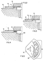
- Fig. 1 is a sectional view of a transducer according to the present invention;
- Fig. 2 is a view showing a detail of Fig. 1;
- Figs. 3 and 4 are views similar to Fig. 1, showing possible changes to the embodiment of Fig. 1; and
- Fig. 5 is a view of a rotating sector.
- The transducer, denoted as a whole at 10, comprises a
carrying plate 11 provided with ahub 12. It has a centeringseat 13, in which thecollimator 14 is received, providing the concentricity thereof with the axis ofshaft 18 carrying therotating sector 16. The angular position 'of thecollimator 14 is defined by a pin 28:, providing the exact position of the collimating slots at thephotodetectors 26. - The
plate 11 is provided with a lug orprojection 15, having the rotating perforatedsector 16 bearing thereon, and which is keyed on arotary shaft 18 made integral therewith by asmall plate 17 connected to saidshaft 18 by means ofrivets 19. Saidshaft 18 is centered in the carryingplate 11 through a singlelong bush 20 inserted in saidhub 12, which is sufficient to endure the radial loads. The axial distance between saidcollimator 14 and rotatingsector 16 is defined by said lug ,orprojection 15. Thecollimator 14 is kept in place by the pressure crown orrim 21, which is provided with a threadeddowel 22 to adjust the pressure being exerted by the crown or rim onshaft 18. - The pressure crown or
rim 21 also clamps said collimator and its peripheral portion. It also serves as a support for the printedcircuit 23 comprising theLEDs 24. - On the opposite outer wall, said carrying
plate 11 supports a further printedcircuit 25 comprising thephotodetectors 26,connector 27 and further known electronic material. - Thus, the whole is completely self-bearing and also able to operate. Therefore, calibrations and other operating tests can be effected thereon.
- As a protection against any environmental factors, the
assembly 10 thus provided may be enclosed within abox 29 withcover 33. - Said sector 16 (Fig. 1 and 5), in addition to
usual transduction perforations 16a, is also provided with a set ofapertures 30 in a same number as said LEDs and photodetectors. They are of same angular dimensions, and accordingly increasing actual dimensions from center to periphery. Thus, it is possible to provide for calibration of the photodetector by only checking the simultaneous response thereof at the calibrating slots. In this case, it is only required to continuously displace the sector by a very small angle, varying the calibration resistance of the photodetectors until the latter will all together match or react both to light and shadow produced by the series of calibratingapertures 30, which are all . perfectly coincident in angular direction. - Fig. 3 is similar to Fig. 2, but therein an
antifriction ring 31 is interposed between saidsector 16 and lug orprojection 15a. - Another solution is shown in Fig. 4, according to which the distance or spacing between said
collimator 14 and rotatingsector 16 is defined by anantifriction ring 32 having the desired height. - Said
collimator 14 andsector 16 may be made in different ways. For example, instead of being of cutout metal, as herein assumed, they may comprise transparent material made opaque by a photosensitive layer, some zones of which are removed by photographic process, thus creating transparent zones for light passage. - Other methods for dulling of a transparent material are provided by vacuum metal depositing, or by a screening process or by paint deposit by a silk screen.
Claims (5)
1. A digital transducer, which can be mounted on a rotary or rotating shaft (18) comprising a rotating sector (16) provided with apertures or perforations (16a) arranged according to arcs on different radiuses, having predetermined angular extension according to a binary code with a selected number of components corresponding to the number of bands of apertures on the different radiuses, information areas being defined for each aperture set positioned on different radiuses included in a predetermined angle characterized by comprising in an area adjacent to the information areas, a set of auxiliary apertures or slots (30) arranged according to arcs with the same angular extension, all aligned on the same angle, an aperture being provided at each information band.
2. A transducer as claimed in Claim 1, characterized by being pack mounted, separately from its own containing box (29, 33), that is the shaft (18) carrying the rotating sector (16) is inserted in a carrying plate (11) provided with a hub (12) and suitable to receive and center the collimator (14), said shaft being centered within the plate hub, then the whole is closed by a pressure crown or rim (21), two printed circuits being provided as mounted one (25) outside the carrying plate (11) and the other (23) outside the pressure crown or rim (21).
3. A transducer as claimed in Claim 2, characterized in that said carrying plate (11) comprises a lug or projection (15) concentric with said hub (12), the side wall of which acts as a centering seat (13) for said collimator (14), whereas the height thereof defines the distance or spacing between said rotating sector (16) and collimator (14).
4. A transducer as claimed in Claim 3, characterized in that said lug or projection (15) at least partly comprises antifriction material.
5. A transducer as claimed in Claim 2, characterized in that said lug or projection (15a) serves only to define the centering of said collimator (14), while the distance or spacing between the latter and said rotating sector (16) is defined by a spacer or thickness (32), particularly of antifriction material.
Priority Applications (1)
| Application Number | Priority Date | Filing Date | Title |
|---|---|---|---|
| EP85100018A EP0187875A1 (en) | 1985-01-02 | 1985-01-02 | A digital transducer |
Applications Claiming Priority (1)
| Application Number | Priority Date | Filing Date | Title |
|---|---|---|---|
| EP85100018A EP0187875A1 (en) | 1985-01-02 | 1985-01-02 | A digital transducer |
Publications (1)
| Publication Number | Publication Date |
|---|---|
| EP0187875A1 true EP0187875A1 (en) | 1986-07-23 |
Family
ID=8193209
Family Applications (1)
| Application Number | Title | Priority Date | Filing Date |
|---|---|---|---|
| EP85100018A Withdrawn EP0187875A1 (en) | 1985-01-02 | 1985-01-02 | A digital transducer |
Country Status (1)
| Country | Link |
|---|---|
| EP (1) | EP0187875A1 (en) |
Cited By (3)
| Publication number | Priority date | Publication date | Assignee | Title |
|---|---|---|---|---|
| DE3939132A1 (en) * | 1989-11-27 | 1991-05-29 | Bodenseewerk Geraetetech | POSITION SENSOR FOR LANDING FLAP LEVER ON AIRCRAFT |
| EP0911611A1 (en) * | 1997-10-21 | 1999-04-28 | Samsung Electronics Co., Ltd. | Rotary encoder |
| CN106017534A (en) * | 2016-07-05 | 2016-10-12 | 北京首钢自动化信息技术有限公司 | Code disc calibration method |
Citations (5)
| Publication number | Priority date | Publication date | Assignee | Title |
|---|---|---|---|---|
| US3728551A (en) * | 1969-10-22 | 1973-04-17 | Southwestern Ind Inc | Mask adjustment mechanism |
| US4086488A (en) * | 1976-10-18 | 1978-04-25 | General Medical Appliance Research Corporation | Digital pressure gauge system |
| GB2038578A (en) * | 1978-12-06 | 1980-07-23 | Plessey Co Ltd | Improvements relating to position indicating systems |
| FR2457477A1 (en) * | 1979-05-25 | 1980-12-19 | Bosch Gmbh Robert | INCREMENTIAL ROTATION SENSOR |
| EP0028138A1 (en) * | 1979-10-26 | 1981-05-06 | Matsushita Electric Industrial Co., Ltd. | Sewing machine |
-
1985
- 1985-01-02 EP EP85100018A patent/EP0187875A1/en not_active Withdrawn
Patent Citations (5)
| Publication number | Priority date | Publication date | Assignee | Title |
|---|---|---|---|---|
| US3728551A (en) * | 1969-10-22 | 1973-04-17 | Southwestern Ind Inc | Mask adjustment mechanism |
| US4086488A (en) * | 1976-10-18 | 1978-04-25 | General Medical Appliance Research Corporation | Digital pressure gauge system |
| GB2038578A (en) * | 1978-12-06 | 1980-07-23 | Plessey Co Ltd | Improvements relating to position indicating systems |
| FR2457477A1 (en) * | 1979-05-25 | 1980-12-19 | Bosch Gmbh Robert | INCREMENTIAL ROTATION SENSOR |
| EP0028138A1 (en) * | 1979-10-26 | 1981-05-06 | Matsushita Electric Industrial Co., Ltd. | Sewing machine |
Cited By (3)
| Publication number | Priority date | Publication date | Assignee | Title |
|---|---|---|---|---|
| DE3939132A1 (en) * | 1989-11-27 | 1991-05-29 | Bodenseewerk Geraetetech | POSITION SENSOR FOR LANDING FLAP LEVER ON AIRCRAFT |
| EP0911611A1 (en) * | 1997-10-21 | 1999-04-28 | Samsung Electronics Co., Ltd. | Rotary encoder |
| CN106017534A (en) * | 2016-07-05 | 2016-10-12 | 北京首钢自动化信息技术有限公司 | Code disc calibration method |
Similar Documents
| Publication | Publication Date | Title |
|---|---|---|
| US4224514A (en) | Optical encoder | |
| US4621256A (en) | Apparatus for measuring rate of angular displacement | |
| EP0054660B1 (en) | Incremental rotary encoder | |
| US4342909A (en) | Optical transducer for detecting the angular position of a rotating member with respect to a fixed structure | |
| US7643017B2 (en) | Servosystem | |
| US4807091A (en) | Illuminating device for an electric part | |
| EP0102241B1 (en) | Optical rotary encoder | |
| EP2382446B1 (en) | Method for mounting a modular rotary encoder and a modular rotary encoder | |
| US4654636A (en) | Displacement measuring apparatus | |
| EP0187875A1 (en) | A digital transducer | |
| US4593269A (en) | Compact optional rotary encoder having adjustable light admitting and receiving components | |
| US4536650A (en) | Optical transducer with a transparent shutter disk | |
| EP1715297A2 (en) | Absolute angle detection apparatus | |
| EP0122294B1 (en) | Optical absolute encoder | |
| US4740691A (en) | Optical rotary encoder and method of assembling the same | |
| US4345149A (en) | Disc-shaped centering fixture for optical encoders | |
| US4289962A (en) | Optoelectronic synchro generator | |
| JP2000131041A (en) | Rotational position sensor and rotational position detecting method | |
| EP0060021A2 (en) | Optical transducer | |
| US5152066A (en) | Angle encoder | |
| JPH10132611A (en) | Rotational displacement information detecting device | |
| US6070020A (en) | Select dial having a click-stop mechanism for a camera | |
| US4154110A (en) | Housing assembly for barometer or other instrument having a settable index | |
| US3765111A (en) | Perpetual calendar | |
| US3209346A (en) | Optical shaft encoder |
Legal Events
| Date | Code | Title | Description |
|---|---|---|---|
| PUAI | Public reference made under article 153(3) epc to a published international application that has entered the european phase |
Free format text: ORIGINAL CODE: 0009012 |
|
| AK | Designated contracting states |
Kind code of ref document: A1 Designated state(s): DE FR GB SE |
|
| STAA | Information on the status of an ep patent application or granted ep patent |
Free format text: STATUS: THE APPLICATION IS DEEMED TO BE WITHDRAWN |
|
| 18D | Application deemed to be withdrawn |
Effective date: 19870124 |
|
| RIN1 | Information on inventor provided before grant (corrected) |
Inventor name: NEGRI, EMILIO |