EP0187784B1 - Testing device for bar-like elements, particularly a framework segment carrying an engineering construction - Google Patents
Testing device for bar-like elements, particularly a framework segment carrying an engineering construction Download PDFInfo
- Publication number
- EP0187784B1 EP0187784B1 EP85903219A EP85903219A EP0187784B1 EP 0187784 B1 EP0187784 B1 EP 0187784B1 EP 85903219 A EP85903219 A EP 85903219A EP 85903219 A EP85903219 A EP 85903219A EP 0187784 B1 EP0187784 B1 EP 0187784B1
- Authority
- EP
- European Patent Office
- Prior art keywords
- load
- load head
- testing apparatus
- head
- force
- Prior art date
- Legal status (The legal status is an assumption and is not a legal conclusion. Google has not performed a legal analysis and makes no representation as to the accuracy of the status listed.)
- Expired - Lifetime
Links
Images


Classifications
-
- G—PHYSICS
- G01—MEASURING; TESTING
- G01M—TESTING STATIC OR DYNAMIC BALANCE OF MACHINES OR STRUCTURES; TESTING OF STRUCTURES OR APPARATUS, NOT OTHERWISE PROVIDED FOR
- G01M5/00—Investigating the elasticity of structures, e.g. deflection of bridges or air-craft wings
- G01M5/0041—Investigating the elasticity of structures, e.g. deflection of bridges or air-craft wings by determining deflection or stress
- G01M5/005—Investigating the elasticity of structures, e.g. deflection of bridges or air-craft wings by determining deflection or stress by means of external apparatus, e.g. test benches or portable test systems
- G01M5/0058—Investigating the elasticity of structures, e.g. deflection of bridges or air-craft wings by determining deflection or stress by means of external apparatus, e.g. test benches or portable test systems of elongated objects, e.g. pipes, masts, towers or railways
Definitions
- the invention relates to a test device for rod-shaped components, in particular structural sections of civil engineering, consisting essentially of a test frame with at least one abutment arrangement for supporting the forces acting on the component to be tested, and at least one displaceable load head connected to a drive device for introducing the loads into the Component, as well as from measuring devices for determining the force quantities applied by the drive device to the load head.
- the components to be tested are subjected to tensile or compressive loads, the loads on the two end faces of the components being introduced into them.
- the components to be tested are sections of the structure cut out of a structure, the load-bearing behavior of which is to be determined.
- the boundary conditions of the components that is, the transition conditions between the structure section and the rest of the structure, are very limited in their variety and are realized by mechanical bearings.
- a fixed abutment arrangement is provided, to which the component is attached at one end, while the other end of the component is supported on the load head.
- the distance between the fixed abutment and the load head can be adjusted.
- a disadvantage of the known test devices is that only mechanical bearings for simple boundary conditions are available as the load head. Rigid clamping of the component is not possible in a simple manner.
- An articulated bearing for example, requires a complex spherical bearing, which is equipped with high-pressure lubrication to avoid friction. Bearings for boundary conditions that are load-dependent cannot be implemented with the known test devices.
- the invention has for its object to develop a test device of the type mentioned in the introduction so that all load-dependent boundary conditions are adjustable.
- any boundary condition of the component can be implemented at any time during component testing.
- the actual values of the boundary conditions of the component can be determined by determining the magnitude and direction of the force quantities applied to the load head by means of the drive device and simultaneously measuring the spatial displacement of the support surface or the support points of the component on the load head relative to the abutment arrangement.
- a control circuit with a process computer is required, with which the control variable for the drive device is determined by comparing the actual and target values of the boundary conditions.
- stepwise displacement of the load head means that all internal forces compatible with the component, such as force and displacement variables, and thus all boundary conditions can be applied, so that the load-bearing behavior of the component can be determined depending on the preselected component Boundary conditions is possible.
- the experiment is regulated in any small load levels.
- the internal forces for load level i be specified.
- the stiffness matrix is estimated for the first load level before the start of the experiment or determined experimentally by means of a planned preload. From the relationship between the displacement of the load head and the measured force quantities applied by the drive device to the load head, the load behavior of the component and thus its instantaneous stiffness matrix can be updated in stages by further load stages.
- the invention leads to a test device which can be made less rigid than the known arrangements. This is possible because the mutual displacements of the cut surfaces of the component are measured. Since a comparatively low rigidity of the test frame does not affect the measurement uncertainty during the test, the test frame can be manufactured more cost-effectively.
- a very simple embodiment results if a longitudinally displaceable load pendulum is provided as the drive device for each degree of freedom, which is articulated with one end on the test frame and with the other end on the load head.
- Three load pendulums are required for level test arrangements, while spatial arrangements require six load pendulums.
- Such load pendulums are longitudinally displaceable rod elements for generating tensile and compressive forces.
- the load pendulums are designed as hydraulic piston-cylinder arrangements which can be acted upon on both sides.
- the load pendulums can also be designed as mechanical spindles, hydraulically drivable piston-cylinder arrangements represent simpler and more cost-effective solutions.
- the load head is designed as a plate arrangement, on the edge regions of which the load pendulums are articulated. Such a plate arrangement enables the necessary firm connection to the test item Component.
- the load pendulums are articulated on the edge areas, so that inclinations and twists of the load head are possible.
- each load pendulum for measuring the normal forces and bending moments in two cross sections of the load pendulum, and a displacement transducer.
- the force transducers are used to determine the amount of force, while the displacement transducers are required to measure the direction of force. This is possible because the load pendulums are articulated at one end on the test frame. Neglecting the frictional forces in the joints of the load pendulums, the measurement of their normal forces is sufficient, however, the frictional forces can be compensated in the proposed embodiment, since the transverse forces can be calculated by determining the bending moments in two cross sections of the load pendulums.
- a further embodiment results if the load head consists of two substantially congruent plates, one plate of which has the bearing surface and the other plate is connected to the drive device, and if force measuring elements are arranged between the plates.
- the drive device can be designed without force measuring devices.
- a measuring pendulum is installed between the load head and the opposite abutment arrangement to determine the spatial displacement of the support surface for each degree of freedom.
- Six measuring pendulums are therefore required for spatial experimental arrangements. With the help of the measuring pendulum, the mutual displacement of the cut surfaces or the support points of the component to be tested is recorded.
- Such measuring pendulums are longitudinally displaceable rod elements with displacement transducers.
- the abutment arrangement opposite the load head can be designed as a further load head which is spatially adjustable by a further drive device.
- the range of possible mutual rotation of the end cut surfaces of the component is expanded.
- half of the load pendulums can be designed as rod elements articulated at both ends without longitudinal displacement. Due to the direct rotation of both cut surfaces of the component, the transverse dimensions of the test devices can be made smaller.
- test device embodiments of the test device are possible with which components with more than two cut surfaces can be tested.
- test device can be implemented in any combination of load heads and / or abutments.
- the test frame consists of a base plate 1, which rests on a foundation 2. Furthermore, vertical supports 3 and 4 connected to the base plate 1 are provided, which are connected at the upper end to a height-displaceable abutment 5.
- the component 6 to be tested is firmly connected at its lower cut surface to a load head 7 designed as a plate arrangement. The upper free end of component 6 is supported on the abutment.
- a load pendulum 8 is attached to the load head 7 with its upper free end at the articulation point 9.
- the lower free end of the load pendulum 8 is connected to the base plate 1 at the articulation point 10.
- the load pendulum 8 is only longitudinally displaceable and is equipped with a hydraulically drivable piston-cylinder arrangement 11 for this purpose.
- a measuring sensor 12 is provided, which consists of suitable force and displacement sensors.
- the load pendulum 13 is designed, which is also articulated on the load plate 7 and on the base plate 1. Furthermore, a load pendulum 14 of identical construction to the load pendulums 8 and 13 is provided, which is articulated on the one hand on a downwardly projecting support lever 7a of the load plate 7 and on the other hand on an upwardly projecting support lever 1a of the base plate 1. On the load head 7 is also a upward support arm 15 attached. Another support arm 16 is attached to the abutment 5 and directed downwards. Between the free end 15a of the support arm 15 and the point 5a on the abutment 5, a measuring pendulum 17 for measuring the distance between the points 5a and 15a is arranged.
- Another measuring pendulum 18 is provided between the points 7b of the load plate 7 and the free end 16a of the support arm 16.
- a third measuring pendulum 20 is located between points 15a and 16a.
- the test device shown in FIG. 1 is set up for three degrees of freedom. So this is a flat test arrangement.
- all boundary conditions can be applied to the component 6 to be tested via the load head 7.
- the loading takes place in arbitrarily small stages, whereby the stiffness matrix for the component must be estimated for the first loading stage.
- suitable displacement of the load pendulums 8, 13 and 14 with respect to the initial state at the start of the test with the component 6 unloaded all of the load and displacement variables compatible with it and thus also all boundary conditions can be applied.
- the forces acting from the load head 7 are detected by the sensors of the load pendulums 8, 13 and 14.
- the normal forces and the bending moments in the load pendulums are measured on two different cross sections, so that their transverse forces can also be determined.
- the measurement of the normal forces in the load pendulums would suffice.
- the other force quantities are required to detect the friction in the articulation points, so that these are eliminated by appropriate compensation of the friction forces and thus do not cause a measurement error.
- the spatial displacement of the bearing surface 7c for the component 6 on the load head 7 is determined with the aid of the measuring pendulums 17, 18 and 20.
- All measured values of the measuring pendulums and measuring sensors in the load pendulums are fed to a process computer 41 shown in FIG. 2, which forms part of a control device 40.
- the load head 7 is actuated by the drive device 42, which consists of the load suspension 8, 13, 14 in Fig. 1.
- the spatial displacements of the load head 7 are detected by the measuring device 43, which comprises the force and measuring sensors 12, 13a, 14a, 17, 18, 20 shown in FIG. 1.
- the control device 40 also contains the program modules 44, 45, 46 of the process computer 41.
- the boundary conditions for the component 6 to be tested can be fed to the module 44 in a freely programmable manner according to arrow 44a in FIG. 2.
- the measured values of the spatial displacement of the load head 7 are transferred from the measuring device 43 to the module 45.
- These suitably transformed actual values of the boundary conditions contained in module 45 are fed with the corresponding setpoints of module 44 to a further module 46, in which the controlled variable for drive device 42 is determined.
- the control is carried out step by step in order to be able to determine its load-bearing behavior even in the case of non-linear relationships between force and displacement variables, i.e. in the plastic area of the component to be tested. In this way, a stiffness matrix estimated for the first load level before the start of the test can be determined step by step.
- the examination of a component with load-dependent boundary conditions can be carried out with the new test device using suitable programming.
- the boundary conditions are not fixed according to arrow 44a, but are specified in a superimposed program loop depending on the experimental result as variable setpoints.
- the behavior of an entire structure can thus be determined, that in an experimentally in the test device and in a section treated only mathematically is broken down, the internal forces being determined iteratively.
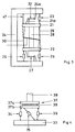
- Fig. 3 shows a simplified representation of a test device which is equipped with a second load head 21 instead of a fixed abutment.
- a longitudinally displaceable load pendulum 23 is articulated on the one hand on the load head 21 and on the other hand on the test frame 24.
- a load pendulum 32 is articulated between the end points of a support lever 21a of the load head 21, which, however, is not displaceable in length.
- the lower load head 22 is connected to the longitudinally displaceable load pendulum 25 and 26 and to a rigid load pendulum 27.
- a component 28 to be tested is firmly connected at its ends to the load heads 21 and 22, respectively.
- Measuring pendulums 29, 30 and 31, which are arranged similarly to the embodiment according to FIG. 1, are used to determine the mutual displacement of the load heads 21 and 22.
- the space requirement can be further reduced by replacing rigid load pendulums with longitudinally displaceable load pendulums.
- FIG. 4 shows a section of a testing device modified compared to FIGS. 1 and 3.
- the lower ends of load pendulums 34, 35 and 36 are articulated on a base plate 33, while their upper ends are hinged to a load head 37.
- the load head 37 consists of an upper plate 37a and a lower plate 37b with the articulation points of the load pendulums 34, 35 and 36.
- the upper plate 37a of the load head 37 is firmly connected to a component 38 to be tested, which is only shown in sections.
Abstract
Description
Die Erfindung betrifft eine Prüfvorichtung für stabförmige Bauteile, insbesondere Tragwerksabschnitte des Ingenieurbaus, im wesentlichen bestehend aus einem Prüfgestell mit wenigstens einer Widerlageranordnung zur Abstützung der auf das zu prüfende Bauteil wirkenden Kräfte, aus wenigstens einem mit einer Antriebsvorrichtung verbundenen verschiebbaren Lastkopf zur Einleitung der Lasten in das Bauteil, sowie aus Meßeinrichtungen zur Bestimmung der von der Antriebseinrichtung auf den Lastkopf aufgebrachten Kraftgrößen.
Mit den bekannten Prüfvorrichtungen werden die zu prüfenden Bauteile auf Zug oder Druck belastet, wobei die Lasten an den beiden Endflächen der Bauteile in diese eingeleitet werden. Die zu prüfenden Bauteile sind aus einem Tragwerk herausgeschnittene Tragwerksabschnitte, deren Tragverhalten zu bestimmen sind. Die Randbedingungen der Bauteile, das sind die Übergangsbedingungen zwischen dem Tragwerksabschnitt und dem übrigen Tragwerk, sind in ihrer Vielfalt stark beschränkt und werden durch mechanische Lager realisiert.The invention relates to a test device for rod-shaped components, in particular structural sections of civil engineering, consisting essentially of a test frame with at least one abutment arrangement for supporting the forces acting on the component to be tested, and at least one displaceable load head connected to a drive device for introducing the loads into the Component, as well as from measuring devices for determining the force quantities applied by the drive device to the load head.
With the known test devices, the components to be tested are subjected to tensile or compressive loads, the loads on the two end faces of the components being introduced into them. The components to be tested are sections of the structure cut out of a structure, the load-bearing behavior of which is to be determined. The boundary conditions of the components, that is, the transition conditions between the structure section and the rest of the structure, are very limited in their variety and are realized by mechanical bearings.
Bei den bekannten Prüfvorrichtungen ist eine feste Widerlageranordnung vorgesehen, an der das Bauteil einendig befestigt ist, während das andere Ende des Bauteils sich auf den Lastkopf abstützt. Um Bauteile unterschiedlicher Länge prüfen zu können, ist der Abstand zwischen dem festen Widerlager und dem Lastkopf einstellbar.In the known test devices, a fixed abutment arrangement is provided, to which the component is attached at one end, while the other end of the component is supported on the load head. In order to be able to test components of different lengths, the distance between the fixed abutment and the load head can be adjusted.
Nachteilig ist bei den bekannten Prüfvorrichtungen, daß als Lastkopf nur mechanische Lager für einfache Randbedingungen erhältlich sind. Eine starre Einspannung des Bauteils ist auf einfache Art nicht möglich. Eine gelenkige Lagerung erfordert beispielsweise ein aufwendiges Kalottenlager, welches zur Vermeidung von Reibung mit einer Hochdruckschmierung ausgerüstet ist. Lager für Randbedingungen, die Lastabhängig sind, können bei den bekannten Prüfvorrichtungen nicht realisiert werden.A disadvantage of the known test devices is that only mechanical bearings for simple boundary conditions are available as the load head. Rigid clamping of the component is not possible in a simple manner. An articulated bearing, for example, requires a complex spherical bearing, which is equipped with high-pressure lubrication to avoid friction. Bearings for boundary conditions that are load-dependent cannot be implemented with the known test devices.
Der Erfindung liegt die Aufgabe zugrunde, eine Prüfvorrichtung der einleitend genannten Art so weiterzubilden, daß sämtliche lastabhängigen Randbedingungen einstellbar sind.The invention has for its object to develop a test device of the type mentioned in the introduction so that all load-dependent boundary conditions are adjustable.
Die Lösung der Aufgabe kennzeichnet sich erfindungsgemäß durch die Merkmale des Anspruchs 1.The solution to the problem is characterized according to the invention by the features of
Da der Lastkopf in Abhängigkeit von der Anzahl der gewählten Freiheitsgrade mit seiner Auflagerfläche für das zu prüfende Bauteil räumlich beliebig verschiebbar ist, kann zu jedem Zeitpunkt der Bauteilprüfung jede beliebige Randbedingung des Bauteils realisiert werden. Hierzu ist es erforderlich, daß das Bauteil an seiner Schnittfläche mit dem Lastkopf fest verbunden ist und dieser durch die Antriebseinrichtung räumlich beliebig verstellbar ist. Durch Bestimmung der mittels der Antriebseinrichtung auf den Lastkopf aufgebrachten Kraftgrößen nach Betrag und Richtung und gleichzeitige Messung der räumlichen Verschiebung der Auflagerfläche bzw. der Auflagerpunkte des Bauteils auf den Lastkopf gegenüber der Widerlageranordnung können die Istwerte der Randbedingungen des Bauteils ermittelt werden.
Zur Verschiebung des Lastkopfes durch die Antriebsvorrichtung ist ein Regelkreis mit einem Prozeßrechner erforderlich, mit welchem durch Vergleich der Ist- und Sollwerte der Randbedingungen die Regelgröße für die Antriebseinrichtung bestimmt wird. Hierbei können die Sollwerte frei programmierbar vorgegeben werden. Somit können auch bei nichtlinearem Zusammenhang von Kraft- und Weggrößen durch schrittweise Verschiebung des Lastkopfes sämtliche mit dem Bauteil strukturmechanisch verträglichen Schnittgrößen, wie Kraft- und Weggrößen, und damit sämtliche Randbedingungen aufgebracht werden, so daß eine Bestimmung des Tragverhaltens des Bauteils in Abhängigkeit von den vorgewählten Randbedingungen möglich ist.Since the load head with its bearing surface for the component to be tested can be moved in any position depending on the number of degrees of freedom selected, any boundary condition of the component can be implemented at any time during component testing. For this purpose, it is necessary that the component is firmly connected to the load head at its cut surface and that the drive head can be spatially adjusted as desired. The actual values of the boundary conditions of the component can be determined by determining the magnitude and direction of the force quantities applied to the load head by means of the drive device and simultaneously measuring the spatial displacement of the support surface or the support points of the component on the load head relative to the abutment arrangement.
To move the load head through the drive device, a control circuit with a process computer is required, with which the control variable for the drive device is determined by comparing the actual and target values of the boundary conditions. The setpoints can be freely programmable. Thus, even in the case of a non-linear connection of force and displacement variables, stepwise displacement of the load head means that all internal forces compatible with the component, such as force and displacement variables, and thus all boundary conditions can be applied, so that the load-bearing behavior of the component can be determined depending on the preselected component Boundary conditions is possible.
Die Regelung des Versuchs erfolgt in beliebig kleinen Belastungsstufen. Für die Steuerung der Verschiebung des Lastkopfes von einer Belastungsstufe i zur Belastungsstufe i + 1 müssen die Schnittgrößen für die Belastungsstufe i vorgegeben werden. Außerdem wird vor Versuchsbeginn für die erste Belastungsstufe die Steifigkeitsmatrix geschätzt oder durch planmäßige Vorbelastung experimentell ermittelt. Aus dem Zusammenhang zwischen der Verschiebung des Lastkopfes und den von der Antriebseinrichtung auf den Lastkopf aufgebrachten gemessenen Kraftgrößen kann durch weitere Laststufen das Tragverhalten des Bauteils und damit dessen momentane Steifigkeitsmatrix stufenweise aktualisiert werden.The experiment is regulated in any small load levels. To control the displacement of the load head from a load level i to load level i + 1, the internal forces for load level i be specified. In addition, the stiffness matrix is estimated for the first load level before the start of the experiment or determined experimentally by means of a planned preload. From the relationship between the displacement of the load head and the measured force quantities applied by the drive device to the load head, the load behavior of the component and thus its instantaneous stiffness matrix can be updated in stages by further load stages.
Unabhängig von der Art der Ausführungsform führt die Erfindung zu einer Prüfvorrichtung, die gegenüber den bekannten Anordnungen weniger steif ausgeführt sein kann. Dies ist möglich, weil die gegenseitigen Verschiebungen der Schnittflächen des Bauteils gemessen werden. Da eine vergleichsweise geringe Steifigkeit des Prüfgestells nicht die Meßunsicherheit bei der Prüfung beeinflußt, kann das Prüfgestell kostengünstiger gefertigt werden.Regardless of the type of embodiment, the invention leads to a test device which can be made less rigid than the known arrangements. This is possible because the mutual displacements of the cut surfaces of the component are measured. Since a comparatively low rigidity of the test frame does not affect the measurement uncertainty during the test, the test frame can be manufactured more cost-effectively.
Eine sehr einfache Ausführungsform ergibt sich, wenn als Antriebseinrichtung je Freiheitsgrad ein längsverschiebbares Belastungspendel vorgesehen ist, welches mit einem Ende am Prüfgestell und mit dem anderen Ende am Lastkopf angelenkt ist. Für ebene Versuchsanordnungen sind drei Belastungspendel erforderlich, während räumliche Anordnungen sechs Belastungspendel erforderlich machen. Derartige Belastungspendel sind längsverschiebbare Stabelemente zur Erzeugung von Zug- und Druckkräften.A very simple embodiment results if a longitudinally displaceable load pendulum is provided as the drive device for each degree of freedom, which is articulated with one end on the test frame and with the other end on the load head. Three load pendulums are required for level test arrangements, while spatial arrangements require six load pendulums. Such load pendulums are longitudinally displaceable rod elements for generating tensile and compressive forces.
Eine betriebssichere Bauweise ergibt sich, wenn die Belastungspendel als beidseitig beaufschlagbare hydraulische Kolbenzylinderanordnungen ausgebildet sind. Zwar können die Belastungspendel auch als mechanische Spindeln ausgeführt sein, jedoch stellen hydraulisch antreibbare Kolbenzylinderanordnungen einfachere und kostengünstigere Lösungen dar. In einer weiteren Ausführungsform ist der Lastkopf als Plattenanordnung ausgebildet, an deren Randbereichen die Belastungspendel angelenkt sind. Eine solche Plattenanordnung ermöglicht die notwendige feste Verbindung zu dem zu prüfenden Bauteil. Die Belastungspendel sind an den Randbereichen angelenkt, so daß Neigungen und Verdrehungen des Lastkopfes möglich sind.An operationally reliable design results if the load pendulums are designed as hydraulic piston-cylinder arrangements which can be acted upon on both sides. Although the load pendulums can also be designed as mechanical spindles, hydraulically drivable piston-cylinder arrangements represent simpler and more cost-effective solutions. In a further embodiment, the load head is designed as a plate arrangement, on the edge regions of which the load pendulums are articulated. Such a plate arrangement enables the necessary firm connection to the test item Component. The load pendulums are articulated on the edge areas, so that inclinations and twists of the load head are possible.
Zweckmäßig ist es, wenn zur vektoriellen Bestimmung der auf den Lastkopf aufgebrachten Kraftgrößen an jedem Belastungspendel zwei im axialen Abstand angeordnete Kraftaufnehmer für die Messung der Normalkräfte und Biegemomente in zwei Querschnitten des Belastungspendels sowie einen Wegaufnehmer vorgesehen sind. Zur Bestimmung des Betrages der Kraftgrößen dienen die Kraftaufnehmer, während die Wegaufnehmer zur Messung der Kraftrichtung erforderlich sind. Dies ist möglich, weil die Belastungspendel einendig ortsfest am Prüfgestell angelenkt sind. Unter Vernachlässigung der Reibkräfte in den Gelenken der Belastungspendel genügt die Messung ihrer Normalkräfte, jedoch können die Reibkräfte in der vorgesehenen Ausführungsform kompensiert werden, da durch Bestimmung der Biegemomente in zwei Querschnitten der Belastungspendel deren Querkräfte berechenbar sind.It is expedient if, for vectorial determination of the force magnitudes applied to the load head, two force transducers arranged at an axial distance are provided on each load pendulum for measuring the normal forces and bending moments in two cross sections of the load pendulum, and a displacement transducer. The force transducers are used to determine the amount of force, while the displacement transducers are required to measure the direction of force. This is possible because the load pendulums are articulated at one end on the test frame. Neglecting the frictional forces in the joints of the load pendulums, the measurement of their normal forces is sufficient, however, the frictional forces can be compensated in the proposed embodiment, since the transverse forces can be calculated by determining the bending moments in two cross sections of the load pendulums.
Eine weitere Ausführungsform ergibt sich, wenn der Lastkopf aus zwei im wesentlichen deckungsgleichen Platten besteht, von denen eine Platte die Auflagerfläche aufweist und die andere Platte mit der Antriebseinrichtung verbunden ist, und wenn zwischen den Platten Kraftmeßelemente angeordnet sind. Auf diese Weise kann die Antriebseinrichtung ohne Kraftmeßeinrichtungen ausgeführt sein.A further embodiment results if the load head consists of two substantially congruent plates, one plate of which has the bearing surface and the other plate is connected to the drive device, and if force measuring elements are arranged between the plates. In this way, the drive device can be designed without force measuring devices.
Vorteilhaft ist es, wenn zur Bestimmung der räumlichen Verschiebung der Auflagerfläche je Freiheitsgrad ein Meßpendel zwischen dem Lastkopf und der gegenüberliegenden Widerlageranordnung eingebaut ist. Fur räumliche Versuchsanordnungen sind somit sechs Meßpendel erforderlich. Mit Hilfe der Meßpendel wird die gegenseitige Verschiebung der Schnittflächen bzw. der Auflagerpunkte des zu prüfenden Bauteils erfaßt. Derartige Meßpendel sind längsverschiebbare Stabelemente mit Wegaufnehmer.It is advantageous if a measuring pendulum is installed between the load head and the opposite abutment arrangement to determine the spatial displacement of the support surface for each degree of freedom. Six measuring pendulums are therefore required for spatial experimental arrangements. With the help of the measuring pendulum, the mutual displacement of the cut surfaces or the support points of the component to be tested is recorded. Such measuring pendulums are longitudinally displaceable rod elements with displacement transducers.
Weiterhin ist es möglich, daß die dem Lastkopf gegenüberliegende Widerlageranordnung als weiterer Lastkopf ausgebildet ist, welcher von einer weiteren Antriebseinrichtung räumlich verstellbar ist. Hierdurch wird der Bereich möglicher gegenseitiger Verdrehung der endseitigen Schnittflächen des Bauteils erweitert. Bei gleicher Anzahl von Freiheitsgraden kann hierbei, gegenüber einer Vorrichtung mit nur einem Lastkopf, die Hälfte der Belastungspendel als beidendig angelenkte Stabelemente ohne Längsverschiebung ausgeführt werden. Durch die unmittelbare Verdrehung beider Schnittflächen des Bauteils können die Querabmessungen der Prüfvorrichtungen kleiner ausgeführt sein.Furthermore, it is possible for the abutment arrangement opposite the load head to be designed as a further load head which is spatially adjustable by a further drive device. As a result, the range of possible mutual rotation of the end cut surfaces of the component is expanded. With the same number of degrees of freedom, compared to a device with only one load head, half of the load pendulums can be designed as rod elements articulated at both ends without longitudinal displacement. Due to the direct rotation of both cut surfaces of the component, the transverse dimensions of the test devices can be made smaller.
Gemäß der Erfindung sind Ausführungsformen der Prüfvorrichtung möglich, mit welchen Bauteile mit mehr als zwei Schnittflächen geprüft werden können.According to the invention, embodiments of the test device are possible with which components with more than two cut surfaces can be tested.
Beispielsweise können zwei feste Widerlageranordnungen für jeweils eine Schnittfläche und ein Lastkopf für eine weitere Schnittfläche des Bauteils vorgesehen sein. Für ein Bauteil mit drei Schnittflächen kann ebenso eine Prüfvorrichtung mit drei voneinander unabhängig verschiebbaren Lastköpfen vorgesehen sein. Für komplizierte Bauteile können entsprechende Prüfvorrichtungen in beliebiger Kombination von Lastköpfen und/oder Widerlagern ausgeführt werden.For example, two fixed abutment arrangements can be provided for one cut surface and one load head for another cut surface of the component. A test device with three load heads that can be displaced independently of one another can also be provided for a component with three cut surfaces. For complex components, corresponding test devices can be implemented in any combination of load heads and / or abutments.
Die Erfindung wird anhand in der Zeichnung schematisch dargestellter Ausführungsbeispiele nachstehend näher erläutert.The invention is explained in more detail below with reference to exemplary embodiments schematically illustrated in the drawing.
Es zeigen :
- Fig. 1
- eine Seitenansicht der neuen Prüfvorrichtung mit einer oberen festen Widerlageranordnung,
- Fig. 2
- ein Blockschaltbild der Regelungseinrichtung für die erfindungsgemäße Prüfvorrichtung nach Fig. 1,
- Fig. 3
- eine Seitenansich einer Prüfvorrichtung in einer gegenüber Fig. 1 veränderten Ausführungsform mit zwei voneinander unabhängigen Lastköpfen und
- Fig. 4
- einen Ausschnitt aus einer gegenüber Fig. 1 und 2 veränderten Prüfvorrichtung mit einem aus zwei Platten bestehenden Lastkopf.
- Fig. 1
- a side view of the new test device with an upper fixed abutment arrangement,
- Fig. 2
- 2 shows a block diagram of the control device for the test device according to the invention according to FIG. 1,
- Fig. 3
- a side view of a test device in a modified from Fig. 1 embodiment with two mutually independent load heads and
- Fig. 4
- a section of a modified compared to FIGS. 1 and 2 test device with a load head consisting of two plates.
Bei der in Fig. 1 dargestellten Prüfvorrichtung besteht das Prüfgestell aus einer Grundplatte 1, welche auf einem Fundament 2 aufliegt. Weiterhin sind mit der Grundplatte 1 verbundene senkrechte Träger 3 und 4 vorgesehen, welche am oberen Ende mit einem höhenverschiebbaren Widerlager 5 verbunden sind. Das zu prüfende Bauteil 6 ist an seiner unteren Schnittfläche mit einem als Plattenanordnung ausgeführten Lastkopf 7 fest verbunden. Das obere freie Ende des Bauteils 6 stützt sich am Widerlager ab.In the test device shown in Fig. 1, the test frame consists of a
Am Lastkopf 7 ist ein Belastungspendel 8 mit seinem oberen freien Ende am Gelenkpunkt 9 befestigt. Das untere freie Ende des Belastungspendels 8 ist am Gelenkpunkt 10 mit der Grundplatte 1 verbunden. Das Belastungspendel 8 ist nur längsverschiebbar und zu diesem Zweck mit einer hydraulisch antreibbaren Kolbenzylinderanordnung 11 ausgerüstet. Zur Messung von Normalkräften und Biegemomenten in zwei im Abstand angeordneten Querschnitten des Belastungspendels 8 und zur Messung der Längsverschiebung des Belastungspendels 8 ist ein Meßaufnehmer 12 vorgesehen, welcher aus geeigneten Kraft- und Wegaufnehmern besteht.A
In gleicher Weise wie das Belastungspendel 8 ist das Belastungspendel 13 ausgeführt, welches ebenfalls an der Lastplatte 7 und an der Grundplatte 1 angelenkt ist. Weiterhin ist ein zu den Belastungspendeln 8 und 13 baugleiches Belastungspendel 14 vorgesehen, welches einerseits an einem nach unten vorspringenden Stützhebel 7a der Lastplatte 7 und andererseits an einem nach oben vorspringenden Stützhebel 1a der Grundplatte 1 angelenkt ist. Am Lastkopf 7 ist außerdem ein nach oben gerichteter Stützarm 15 befestigt. Ein weiterer Stützarm 16 ist am Widerlager 5 befestigt und nach unten gerichtet. Zwischen dem freien Ende 15a des Stützarms 15 und dem Punkt 5a am Widerlager 5 ist ein Meßpendel 17 zur Abstandsmessung zwischen den Punkten 5a und 15a angeordnet. Ein weiteres Meßpendel 18 ist zwischen den Punkten 7b der Lastplatte 7 und dem freien Ende 16a des Stützarms 16 vorgesehen. Ein drittes Meßpendel 20 befindet sich zwischen den Punkten 15a und 16a. Diese Meßpendel sind längsverschiebbare Stabelemente mit einem Wegaufnehmer.In the same way as the
Die in Fig. 1 dargestellte Prüfvorrichtung ist für drei Freiheitsgrade eingerichtet. Hierbei handelt es sich also um eine ebene Versuchsanordnung. Durch entsprechende Längsverschiebungen der Belastungspendel 8, 13 und 14 können sämtliche Randbedingungen über den Lastkopf 7 auf das zu prüfende Bauteil 6 aufgebracht werden. Die Belastung erfolgt hierbei in beliebig kleinen Stufen, wobei für die erste Belastungsstufe die Steifigkeitsmatrix für das Bauteil geschätzt werden muß. Durch geeignete Verschiebung der Belastungspendel 8, 13 und 14 gegenüber dem Ausgangszustand am Versuchsbeginn bei unbelasteten Bauteil 6 können alle mit diesem verträglichen Last- und Weggrößen und somit auch alle Randbedingungen aufgebracht werden. Die aus den Lastkopf 7 wirkenden Kräfte werden durch die Meßaufnehmer der Belastungspendel 8, 13 und 14 erfaßt. Hierbei werden die Normalkräfte sowie an zwei verschiedenen Querschnitten die Biegemomente in den Belastungspendeln gemessen, so daß deren Querkräfte ebenfalls bestimmbar sind. Bei reibfreien Gelenken 9 und 10 des Belastungspendels 8 und den entsprechenden Gelenken der Belastungspendel 13 und 14 würde die Messung der Normalkräfte in den Belastungspendeln genügen. Zur Erfassung der Reibung in den Gelenkpunkten werden die weiteren Kraftgrößen benötigt, so daß durch entsprechende Kompensation der Reibkräfte diese eliminiert werden und somit keinen Meßfehler verursachen. Die räumliche Verschiebung der Auflagerfläche 7c für das Bauelement 6 auf dem Lastkopf 7 wird mit Hilfe der Meßpendel 17, 18 und 20 bestimmt.The test device shown in FIG. 1 is set up for three degrees of freedom. So this is a flat test arrangement. By corresponding longitudinal displacements of the
Sämtliche Meßwerte der Meßpendel und Meßaufnehmer in den Belastungspendeln werden einem in Fig. 2 dargestellten Prozeßrechner 41 zugeführt, welcher einen Teil einer Regelungseinrichtung 40 bildet. Hierbei wird der Lastkopf 7 von der Antriebseinrichtung 42 betätigt, welche aus den Belastungspendein 8, 13, 14 in Fig. 1 besteht. Die räumlichen Verschiebungen des Lastkopfes 7 werden von der Meßeinrichtung 43 erfaßt, welche die in Fig. 1 dargestellten Kraft- und Meßaufnehmer 12, 13a, 14a, 17, 18, 20 umfaßt. Die Regelungseinrichtung 40 enthält weiterhin die Programmodule 44, 45, 46 des Prozeßrechners 41.All measured values of the measuring pendulums and measuring sensors in the load pendulums are fed to a
Die Randbedingungen für das zu prüfende Bauteil 6 können gemäß Pfeil 44a in Fig. 2 frei programmierbar dem Modul 44 zugeführt werden. Die Meßwerte der räumlichen Verschiebung des Lastkopfes 7 werden von der Meßeinrichtung 43 dem Modul 45 übergeben. Diese im Modul 45 enthaltenen und geeignet umgeformten Istwerte der Randbedingungen werden mit den entsprechenden Sollwerten des Moduls 44 einem weiterem Modul 46 zugeführt, in welchem die Regelgröße für die Antriebseinrichtung 42 ermittelt wird.The boundary conditions for the
Die Regelung erfolgt schrittweise, um auch bei nichtlinearen Zusammenhängen zwischen Kraft- und Weggrößen, also im plastischen Bereich des zu prüfenden Bauteils, dessen Tragverhalten bestimmen zu können. Auf diese Weise kann eine vor Versuchsbeginn für die erste Belastungsstufe geschätzte Steifigkeitsmatrix stufenweise ermittelt werden.The control is carried out step by step in order to be able to determine its load-bearing behavior even in the case of non-linear relationships between force and displacement variables, i.e. in the plastic area of the component to be tested. In this way, a stiffness matrix estimated for the first load level before the start of the test can be determined step by step.
Die Untersuchung eines Bauteils mit lastabhängigen Randbedingungen läßt sich mit der neuen Prüfvorrichtung durch geeignete Programmierung durchführen. Hierbei werden die Randbedingungen nicht gemäß Pfeil 44a fest eingestellt, sondern werden in einer überlagerten Programmschleife in Abhängigkeit vom experimentellen Ergebnis als variable Sollwerte vorgegeben. Somit kann das Verhalten eines gesamten Tragwerkes bestimmt werden, das in einen experimentell in der Prüfvorrichtung und in einem nur rechnerisch behandelten Abschnitt zerlegt wird, wobei die Schnittgrößen iterativ ermittelt werden.The examination of a component with load-dependent boundary conditions can be carried out with the new test device using suitable programming. The boundary conditions are not fixed according to arrow 44a, but are specified in a superimposed program loop depending on the experimental result as variable setpoints. The behavior of an entire structure can thus be determined, that in an experimentally in the test device and in a section treated only mathematically is broken down, the internal forces being determined iteratively.
Fig. 3 zeigt in vereinfachter Darstellung eine Prüfvorrichtung, welche anstelle eines festen Widerlagers mit einem zweiten Lastkopf 21 ausgerüstet ist. Ein längsverschiebbares Belastungspendel 23 ist einerseits am Lastkopf 21 und andererseits am Prüfgestell 24 angelenkt. Außerdem ist zwischen den Endpunkten eines Stützhebels 21a des Lastkopfes 21 ein Belastungspendel 32 angelenkt, welches in der Länge jedoch nicht verschiebbar ist.Fig. 3 shows a simplified representation of a test device which is equipped with a
Der untere Lastkopf 22 ist mit dem längsverschiebbaren Belastungspendeln 25 und 26 sowie mit einem starren Belastungspendel 27 verbunden. Ein zu prüfendes Bauteil 28 ist an seinen Enden jeweils mit den Lastköpfen 21 und 22 fest verbunden. Zur Bestimmung der gegenseitigen Verschiebung der Lastköpfe 21 und 22 dienen Meßpendel 29, 30 und 31, die ähnlich wie bei der Ausführungsform gemäß Fig. 1 angeordnet sind.The
Bei der Prüfvorrichtung nach Fig. 3 handelt es sich ebenfalls um eine ebene Versuchsanordnung. Ebenso wie bei der Fig. 1 sind für die Lastkopfe 21 und 22 insgesamt drei längsverschiebbare Belastungspendel erforderlich. Bei gleicher Anzahl von Freiheitsgraden können die Belastungspendel 27, 32 und 47 starr ausgeführt werden. Da bei der Prüfvorrichtung nach Fig. 3 beide Schnittflächen des Bauteils 28 jeweils gegeneinander geneigt werden können, benötigt diese Vorrichtung nur einen geringen Raumbedarf senkrecht zur Längsachse des Bauteils 28.3 is also a flat test arrangement. As in FIG. 1, a total of three longitudinally displaceable load pendulums are required for the load heads 21 and 22. With the same number of degrees of freedom, the
Durch den Ersatz von starren Belastungspendeln durch längsverschiebbaren Belastungspendel kann der Raumbedarf weiter eingeschränkt werden.The space requirement can be further reduced by replacing rigid load pendulums with longitudinally displaceable load pendulums.
Fig. 4 zeigt einen Ausschnitt aus einer gegenüber Fig. 1 und 3 veränderten Prüfvorrichtung. Auf einer Grundplatte 33 sind die unteren Enden von Belastungspendel 34, 35 und 36 angelenkt, während deren obere Enden an einem Lastkopf 37 angelenkt sind. Der Lastkopf 37 besteht aus einer oberen Platte 37a sowie einer unteren Platte 37b mit den Anlenkpunkten der Belastungspendel 34, 35 und 36. Die obere Platte 37a des Lastkopfes 37 ist mit einem nur abschnittsweise dargestellten zu prüfenden Bauteil 38 fest verbunden. Zwischen den Platten 37a und 37b des Lastkopfes 37 befindet sich eine Mehrkomponenten-Kraftmeßeinrichtung 39, mit welcher die auf den Lastkopf 37 wirkenden Größen bestimmt werden können. Auf diese Weise kann auf die im Zusammenhang mit Fig. 1 beschriebenen Meßaufnehmer in den Belastungspendeln verzichtet werden.FIG. 4 shows a section of a testing device modified compared to FIGS. 1 and 3. The lower ends of
Claims (8)
- Testing apparatus for rod shaped structural components, particularly supporting structure segments of an engineering structure, substantially comprising a testing support with at least one abutment arrangement for supporting the forces being applied to the structural component being tested, at least one shiftable load head connected to a propulsion device for introducing the loads into the structural component, as well as measuring devices for determining the values of force applied by the propulsion device to the load head, characterized in that the load head (7, 21, 22, 37) has a support surface (7c) which can be shifted at any number of degrees of freedom for setting any desired boundary conditions of the structural component (6, 28, 38) and which can be fixed to the structural component (6, 28, 38) for all boundary conditions; that the measuring devices (12, 13a, 14a, 20) are provided for vectorially determining the values of force for all degrees of freedom; that further measuring devices (17, 18, 20, 29, 30, 31) are built in for determining the spatial shifting of the support surface (7c) compared with the opposing abutment arrangement (5); and that for shifting the load head (7, 21, 22, 37), a control device (40) is provided, in which a controlled condition for the propulsion device (42) can be derived from the measurement values gained from the measuring devices (43) and the preselected desired values of the boundary conditions in a process computer (41).
- Testing apparatus according to claim 1, characterized in that as propulsion device, for every degree of freedom, a longitudinally shiftable loading pendulum (8, 13, 14, 22, 23, 25, 26, 34, 35, 36) is provided which is pivoted at one end to the testing support and at the other end to the load head (7, 21, 22, 37).
- Testing apparatus according to claim 2, characterized in that each loading pendulum (8) is a both side loadable hydraulic piston cylinder arrangement (11).
- Testing apparatus according to claim 2 or 3, characterized in that the load head (37) is a plate arrangement, each loading pendulum (8, 13, 14) is pivoted at the peripheries of said plate arrangement.
- Testing apparatus according to one of the claims 2 to 4, characterized in that for vectorially determining the values of force applied to the load head (7), each loading pendulum (8, 13, 14) comprises a displacement pick up and two force receivers arranged at an axial distance for the measurement of the normal forces and bending moments in two cross sections of the loading pendulum.
- Testing apparatus according to one of the preceding claims, characterized in that the load head (37) comprises two plates (37a, 37b) which are substantially coincident, one plate (37a) of which comprises the support surface and the other plate (37b) is connected to the propulsion device, and that between the plates (37a, 37b) force measuring elements (39) are positioned for a number of components according to the degrees of freedom.
- Testing apparatus according to one of the preceding claims, characterized in that one measuring pendulum (17, 18, 20) for each degree of freedom is built in between the load head (7) and the opposing abutment arrangement (5) for determining the spatial shifting of the support surface (7c).
- Testing apparatus according to one of the preceding claims, characterized in that the abutment arrangement opposite the load head (22) forms another load head (21), which can be spatially shifted by a further propulsion device.
Priority Applications (1)
| Application Number | Priority Date | Filing Date | Title |
|---|---|---|---|
| AT85903219T ATE87097T1 (en) | 1984-07-10 | 1985-07-04 | TESTING DEVICE FOR ROD-SHAPED COMPONENTS, IN PARTICULAR STRUCTURAL SECTION OF ENGINEERING. |
Applications Claiming Priority (2)
| Application Number | Priority Date | Filing Date | Title |
|---|---|---|---|
| DE3425359 | 1984-07-10 | ||
| DE3425359A DE3425359C2 (en) | 1984-07-10 | 1984-07-10 | Test device for rod-shaped components, in particular structural sections in civil engineering |
Publications (2)
| Publication Number | Publication Date |
|---|---|
| EP0187784A1 EP0187784A1 (en) | 1986-07-23 |
| EP0187784B1 true EP0187784B1 (en) | 1993-03-17 |
Family
ID=6240267
Family Applications (1)
| Application Number | Title | Priority Date | Filing Date |
|---|---|---|---|
| EP85903219A Expired - Lifetime EP0187784B1 (en) | 1984-07-10 | 1985-07-04 | Testing device for bar-like elements, particularly a framework segment carrying an engineering construction |
Country Status (5)
| Country | Link |
|---|---|
| EP (1) | EP0187784B1 (en) |
| JP (1) | JPS62501098A (en) |
| AT (1) | ATE87097T1 (en) |
| DE (2) | DE3425359C2 (en) |
| WO (1) | WO1986000702A1 (en) |
Cited By (1)
| Publication number | Priority date | Publication date | Assignee | Title |
|---|---|---|---|---|
| CN109489922A (en) * | 2018-11-15 | 2019-03-19 | 华北科技学院 | It is a kind of for testing the experimental rig of flexible support mechanical property |
Families Citing this family (3)
| Publication number | Priority date | Publication date | Assignee | Title |
|---|---|---|---|---|
| US5056370A (en) * | 1990-07-19 | 1991-10-15 | Wolfgang Maier | Method and apparatus for testing a test piece |
| DE4204589A1 (en) * | 1992-02-15 | 1993-08-19 | Mtu Muenchen Gmbh | MATERIALS TEST DEVICE FOR TENSION OR PRESSURE TESTS |
| WO2001014845A1 (en) * | 1999-08-25 | 2001-03-01 | Ap Automotive Systems, Inc. | Dual mast system for simulation testing |
Family Cites Families (2)
| Publication number | Priority date | Publication date | Assignee | Title |
|---|---|---|---|---|
| US2446566A (en) * | 1946-01-22 | 1948-08-10 | Jr Edward Wenk | Model testing apparatus |
| JPS5619744B2 (en) * | 1974-10-01 | 1981-05-09 |
-
1984
- 1984-07-10 DE DE3425359A patent/DE3425359C2/en not_active Expired
-
1985
- 1985-07-04 WO PCT/DE1985/000228 patent/WO1986000702A1/en active IP Right Grant
- 1985-07-04 AT AT85903219T patent/ATE87097T1/en not_active IP Right Cessation
- 1985-07-04 JP JP60503128A patent/JPS62501098A/en active Granted
- 1985-07-04 EP EP85903219A patent/EP0187784B1/en not_active Expired - Lifetime
- 1985-07-04 DE DE8585903219T patent/DE3587193D1/en not_active Expired - Fee Related
Cited By (1)
| Publication number | Priority date | Publication date | Assignee | Title |
|---|---|---|---|---|
| CN109489922A (en) * | 2018-11-15 | 2019-03-19 | 华北科技学院 | It is a kind of for testing the experimental rig of flexible support mechanical property |
Also Published As
| Publication number | Publication date |
|---|---|
| JPS62501098A (en) | 1987-04-30 |
| DE3587193D1 (en) | 1993-04-22 |
| WO1986000702A1 (en) | 1986-01-30 |
| JPH037896B2 (en) | 1991-02-04 |
| ATE87097T1 (en) | 1993-04-15 |
| DE3425359C2 (en) | 1986-12-11 |
| DE3425359A1 (en) | 1986-01-30 |
| EP0187784A1 (en) | 1986-07-23 |
Similar Documents
| Publication | Publication Date | Title |
|---|---|---|
| DE2758340C2 (en) | ||
| EP0396212A2 (en) | Apparatus and procedure for the uniaxial mechanical testing of materials | |
| DE3331708C2 (en) | ||
| DE2209845A1 (en) | Measuring device, in particular storage for measuring sensors | |
| EP3845874A1 (en) | Shelf bracket | |
| EP2408590B1 (en) | Method and apparatus for adjusting a machine | |
| DE102007036214B4 (en) | Automated dead weight measuring machine for the calibration of strain gauges | |
| DE102014215189A1 (en) | Method of re-installing an article to be stored | |
| EP0187784B1 (en) | Testing device for bar-like elements, particularly a framework segment carrying an engineering construction | |
| DE3440670A1 (en) | Device for measuring the forces acting on machine components | |
| DE2926213A1 (en) | Wind tunnel force and torque measurement - using pyramid balance with torque measurement frame object support and force cells | |
| EP3191236B1 (en) | Press brake and a method for bending a workpiece with the bending press | |
| DE19939549A1 (en) | Test stand for measuring buckling strength e,g. of vehicle body components, with test head traversing along x and y axes | |
| DE3113753C2 (en) | Three roll bending machine for sheet metal | |
| DE2331149C3 (en) | Support of the load bridge of a weighbridge connected to a load cell | |
| EP0212448B1 (en) | Device for decomposing vector forces | |
| DE19602712A1 (en) | Determining experimental or trial data for quality prognosis of tool post or tool box construction | |
| DE3927475C2 (en) | ||
| DE102014117244A1 (en) | Coordinate measuring machine and method for compensation of large workpiece masses | |
| DE102019112909B4 (en) | Test stand for the bridge of a body tunnel and use of such a test stand | |
| DE4016038C2 (en) | ||
| DE10254062B4 (en) | Method and device for determining bulk material parameters | |
| DE2156410A1 (en) | LIBRA | |
| DE2351229C2 (en) | Support of the load bridge of a weighbridge connected to a load cell | |
| DE2654330A1 (en) | Dynamometer calibration and checking appts. - has hydraulic cylinder and weights for applying force to dynamometer through master dynamometer and directly respectively (SW 5.6.78) |
Legal Events
| Date | Code | Title | Description |
|---|---|---|---|
| PUAI | Public reference made under article 153(3) epc to a published international application that has entered the european phase |
Free format text: ORIGINAL CODE: 0009012 |
|
| 17P | Request for examination filed |
Effective date: 19860308 |
|
| AK | Designated contracting states |
Kind code of ref document: A1 Designated state(s): AT BE CH DE FR GB IT LI NL SE |
|
| 17Q | First examination report despatched |
Effective date: 19870811 |
|
| 18D | Application deemed to be withdrawn |
Effective date: 19880201 |
|
| 18RA | Request filed for re-establishment of rights before grant |
Effective date: 19890113 |
|
| 19U | Interruption of proceedings before grant |
Effective date: 19870731 |
|
| 19W | Proceedings resumed before grant after interruption of proceedings |
Effective date: 19890113 |
|
| D18D | Application deemed to be withdrawn (deleted) | ||
| R18Z | Request filed for re-establishment of rights before grant (corrected) | ||
| GRAA | (expected) grant |
Free format text: ORIGINAL CODE: 0009210 |
|
| AK | Designated contracting states |
Kind code of ref document: B1 Designated state(s): AT BE CH DE FR GB IT LI NL SE |
|
| REF | Corresponds to: |
Ref document number: 87097 Country of ref document: AT Date of ref document: 19930415 Kind code of ref document: T |
|
| REF | Corresponds to: |
Ref document number: 3587193 Country of ref document: DE Date of ref document: 19930422 |
|
| GBT | Gb: translation of ep patent filed (gb section 77(6)(a)/1977) |
Effective date: 19930406 |
|
| PGFP | Annual fee paid to national office [announced via postgrant information from national office to epo] |
Ref country code: SE Payment date: 19930611 Year of fee payment: 9 |
|
| ITF | It: translation for a ep patent filed |
Owner name: MODIANO & ASSOCIATI S.R.L. |
|
| PGFP | Annual fee paid to national office [announced via postgrant information from national office to epo] |
Ref country code: FR Payment date: 19930618 Year of fee payment: 9 |
|
| PGFP | Annual fee paid to national office [announced via postgrant information from national office to epo] |
Ref country code: GB Payment date: 19930622 Year of fee payment: 9 |
|
| PGFP | Annual fee paid to national office [announced via postgrant information from national office to epo] |
Ref country code: BE Payment date: 19930705 Year of fee payment: 9 |
|
| PGFP | Annual fee paid to national office [announced via postgrant information from national office to epo] |
Ref country code: AT Payment date: 19930712 Year of fee payment: 9 |
|
| ET | Fr: translation filed | ||
| PGFP | Annual fee paid to national office [announced via postgrant information from national office to epo] |
Ref country code: CH Payment date: 19930727 Year of fee payment: 9 |
|
| PGFP | Annual fee paid to national office [announced via postgrant information from national office to epo] |
Ref country code: NL Payment date: 19930731 Year of fee payment: 9 |
|
| PLBE | No opposition filed within time limit |
Free format text: ORIGINAL CODE: 0009261 |
|
| STAA | Information on the status of an ep patent application or granted ep patent |
Free format text: STATUS: NO OPPOSITION FILED WITHIN TIME LIMIT |
|
| 26N | No opposition filed | ||
| PG25 | Lapsed in a contracting state [announced via postgrant information from national office to epo] |
Ref country code: GB Effective date: 19940704 Ref country code: AT Effective date: 19940704 |
|
| PG25 | Lapsed in a contracting state [announced via postgrant information from national office to epo] |
Ref country code: SE Effective date: 19940705 |
|
| PG25 | Lapsed in a contracting state [announced via postgrant information from national office to epo] |
Ref country code: LI Effective date: 19940731 Ref country code: CH Effective date: 19940731 Ref country code: BE Effective date: 19940731 |
|
| BERE | Be: lapsed |
Owner name: MAIER WOLFGANG Effective date: 19940731 |
|
| EUG | Se: european patent has lapsed |
Ref document number: 85903219.5 Effective date: 19950210 |
|
| PG25 | Lapsed in a contracting state [announced via postgrant information from national office to epo] |
Ref country code: NL Effective date: 19950201 |
|
| GBPC | Gb: european patent ceased through non-payment of renewal fee |
Effective date: 19940704 |
|
| NLV4 | Nl: lapsed or anulled due to non-payment of the annual fee | ||
| PGFP | Annual fee paid to national office [announced via postgrant information from national office to epo] |
Ref country code: DE Payment date: 19950321 Year of fee payment: 10 |
|
| PG25 | Lapsed in a contracting state [announced via postgrant information from national office to epo] |
Ref country code: FR Effective date: 19950331 |
|
| REG | Reference to a national code |
Ref country code: CH Ref legal event code: PL |
|
| EUG | Se: european patent has lapsed |
Ref document number: 85903219.5 |
|
| REG | Reference to a national code |
Ref country code: FR Ref legal event code: ST |
|
| PG25 | Lapsed in a contracting state [announced via postgrant information from national office to epo] |
Ref country code: DE Effective date: 19960402 |