EP0187455A2 - Electrical apparatus - Google Patents
Electrical apparatus Download PDFInfo
- Publication number
- EP0187455A2 EP0187455A2 EP85308387A EP85308387A EP0187455A2 EP 0187455 A2 EP0187455 A2 EP 0187455A2 EP 85308387 A EP85308387 A EP 85308387A EP 85308387 A EP85308387 A EP 85308387A EP 0187455 A2 EP0187455 A2 EP 0187455A2
- Authority
- EP
- European Patent Office
- Prior art keywords
- circuit
- electrical
- electrical apparatus
- generating
- rectifier circuit
- Prior art date
- Legal status (The legal status is an assumption and is not a legal conclusion. Google has not performed a legal analysis and makes no representation as to the accuracy of the status listed.)
- Withdrawn
Links
Images


Classifications
-
- H—ELECTRICITY
- H02—GENERATION; CONVERSION OR DISTRIBUTION OF ELECTRIC POWER
- H02H—EMERGENCY PROTECTIVE CIRCUIT ARRANGEMENTS
- H02H7/00—Emergency protective circuit arrangements specially adapted for specific types of electric machines or apparatus or for sectionalised protection of cable or line systems, and effecting automatic switching in the event of an undesired change from normal working conditions
- H02H7/10—Emergency protective circuit arrangements specially adapted for specific types of electric machines or apparatus or for sectionalised protection of cable or line systems, and effecting automatic switching in the event of an undesired change from normal working conditions for converters; for rectifiers
- H02H7/12—Emergency protective circuit arrangements specially adapted for specific types of electric machines or apparatus or for sectionalised protection of cable or line systems, and effecting automatic switching in the event of an undesired change from normal working conditions for converters; for rectifiers for static converters or rectifiers
- H02H7/125—Emergency protective circuit arrangements specially adapted for specific types of electric machines or apparatus or for sectionalised protection of cable or line systems, and effecting automatic switching in the event of an undesired change from normal working conditions for converters; for rectifiers for static converters or rectifiers for rectifiers
- H02H7/1255—Emergency protective circuit arrangements specially adapted for specific types of electric machines or apparatus or for sectionalised protection of cable or line systems, and effecting automatic switching in the event of an undesired change from normal working conditions for converters; for rectifiers for static converters or rectifiers for rectifiers responsive to internal faults, e.g. by monitoring ripple in output voltage
-
- G—PHYSICS
- G01—MEASURING; TESTING
- G01R—MEASURING ELECTRIC VARIABLES; MEASURING MAGNETIC VARIABLES
- G01R31/00—Arrangements for testing electric properties; Arrangements for locating electric faults; Arrangements for electrical testing characterised by what is being tested not provided for elsewhere
- G01R31/50—Testing of electric apparatus, lines, cables or components for short-circuits, continuity, leakage current or incorrect line connections
- G01R31/52—Testing for short-circuits, leakage current or ground faults
-
- G—PHYSICS
- G01—MEASURING; TESTING
- G01R—MEASURING ELECTRIC VARIABLES; MEASURING MAGNETIC VARIABLES
- G01R31/00—Arrangements for testing electric properties; Arrangements for locating electric faults; Arrangements for electrical testing characterised by what is being tested not provided for elsewhere
- G01R31/50—Testing of electric apparatus, lines, cables or components for short-circuits, continuity, leakage current or incorrect line connections
- G01R31/54—Testing for continuity
Definitions
- This invention relates to an electrical apparatus suitable for monitoring electrical continuity in an electrical circuit.
- the invention finds particular, though not exclusive, application in monitoring electrical continuity in an a.c. power supply, and especially in the rectifier circuit associated with a multi-phase power supply.
- Detection of a discontinuity in the rectifier circuit of a multi-phase power supply can be particularly important if an equipment being supplied performs a vital operational function - as in the case of equipment used in signalling or other supervisory systems, for example.
- a potentially hazardous situation could develop if a discontinuity occurs in one, or only some, of the input arms of the rectifier circuit since, in these circumstances, an associated equipment may continue to function, but its performance may be impaired.
- an electrical apparatus used to monitor electrical continuity should be relatively insensitive to transient effects which are of little inherent interest e.g. a temporary interruption in the mains supply.
- an electrical apparatus suitable for monitoring electrical continuity in an electrical circuit, the apparatus comprising means for generating a succession of pulses while an electrical signal prevails in the circuit and means for generating an alarm signal, to indicate an open circuit condition, if an interruption in said succession persists for at least a preset interval of time.
- the electrical apparatus includes a first timing circuit for generating a first electrical signal if said interruption persists at least for a first portion of said interval of time and a second timing signal, responsive to a said first electrical signal, to generate said alarm signal if the interruption persists for the remaining portion of said interval of time.
- the first and second timing circuits may include monostable circuits which have respective time constants related to said first and remaining portions of said interval of time.
- said succession of pulses has a periodicity of 20 ms and said first and remaining portions are respectivly of 70 ms and 150 ms duration.
- the said time interval is 220 ms and so an alarm will be generated if an open circuit condition persists for a minimum of 200 ms.
- the electrical apparatus is suitable for monitoring electrical continuity in respective input arms of a rectifier circuit.
- a respective said pulse generating means and a respective said first timing circuit may be provided to monitor an electrical signal prevailing in each input arm of the rectifier circuit and said second timing circuit is arranged to respond to a said first electrical signal generated by any one of the first timing circuits.
- said second electrical circuit can be arranged so as to be capable of generating an alarm signal provided also that the magnitude of an electrical signal in at least one of the input arms exceeds a threshold value.
- Respective current sensing means may be provided for connection in each input arm of the rectifier circuit or, alternatively, when space is limited, current sensing means may be provided to sense current in a supply line for respective input arms of the rectifier circuit, the current sensing means including a circuit capable of responding to the positive and negative half cycles of the supply waveform to generate, at different output locations, electrical signals corresponding to the current in said respective input arms.
- an open circuit arm detector shown in Figure 1 is used to monitor electrical continuity in respective arms of a rectifier circuit.
- the rectifier circuit may be configured, as shown in Figure 2a, to receive power from a 3-phase supply or alternatively, as shown in Figure 2b, from a 6-phase, single way (half wave) supply.
- the input current i a1 ....i a6 prevailing in each arm A 1 ....A 6 of the rectifier circuit is monitored by means of a respective current transformer CT ....CT 6 .
- the primary winding W1 of each transformer is connected in series with a diode D 1 ....D 6 in a respective arm and a voltage, proportional to the input current in that arm, is developed across the secondary winding W2.
- the voltages developed in this manner are applied to respective input terminals I 1 ....I 6 of the detector shown in Figure 1.
- the detector operates on the received voltages and generates an alarm signal if a discontinuity in any one of the input arms persists for longer than a predetermined interval of time. If desired, the alarm signal may be used to de-energise the rectifier circuit thereby to disconnect an associated equipment which might otherwise be damaged or operate in an unreliable or dangerous manner.
- Voltages applied at input terminals I 1 ....I 6 are operated on, initially by respective circuits shown generally at 10, 20 .... 60. These circuits are identical and only one of them, circuit 10, will be described in detail.
- a voltage applied at input terminal I 1 of circuit 10 is used to drive a comparator 12.
- the comparator generates a train of CMOS trigger pulses P which are fed to the input of an monostable circuit 13.
- the trigger pulses have a periodicity of 20 ms and the monostable circuit is arranged to have a time constant of 70 ms.
- circuit 13 assumes the unstable condition if the pulse train is applied continuously at its input. However, if an interruption of more than 70 ms occurs the circuit reverts to the stable condition and its output goes low, indicating that an open circuit condition may have arisen in the associated input arm of the rectifier circuit.
- the amplitudes of the applied voltages are compared with a threshold voltage V T in a comparator 71.
- the threshold voltage is set at a suitable value corresponding to the minimum operating current imin in the input arms of the rectifier circuit. If the applied voltage, associated with any of the input arms, exceeds the threshold voltage V T comparator 71 generates an output signal which is fed to another monostable circuit 72 whose input and output locations are connected to respective input terminals of a NAND gate 73. With this arrangement a low produced at the output of gate 73 indicates that at least one of the input arms carries the minimum operating current.
- the output of gate 73 is coupled to one input terminal A of another NAND gate 80, the other input terminal B being coupled commonly to the outputs of the monostable circuits 13, 23 .... 63 in circuits 10 .... 60. If both inputs to gate 80 are simultaneously low a potential fault detected by one or more circuits 10 .... 60 is likely to be of significance. In these circumstances the output of gate 80 goes high and triggers a yet further monostable circuit 81.
- the input and output locations of circuit 81 are connected to respective input locations of a further NAND gate 82.
- monostable circuit 81 has a time constant of 150 ms; if both inputs to gate 80 remain low for this length of time, thereby indicating that an interruption in the pulse train, detected by one or more of circuits 10 .... 60, has persisted for 220 ms, NAND gate 82 produces an alarm signal AS suitable to cause a change of state in a bistable circuit 90.
- response circuit 90 renders a transistor 91 non-conductive thereby causing a relay 92 to de-energise and triggering a number of alarms which may be located at remote monitoring stations. If desired, the relay may also be used to de-energise the rectifier circuit.
- a signal generated at the output of bistable circuit 90 is also used to trigger a latch circuit 100 connected, as shown, to circuits 10 .... 60 so as to sample, and store data indicative of, the voltage levels prevailing at the inverted outputs of monostable circuits 13 .... 63.
- the latch when triggered, drives appropriate ones of a plurality of transistors T 1 .... T 6 in accordance with the stored data. If an open circuit condition is detected in an input arm of the rectifier circuit the latch drives the correspondiong transistor which, in turn, energises an associated LED (as shown).
- the LEDS provide a display capable, when energised, of showing the location of any detected fault.
- bistable circuit 90 is not used to control transistor 91; instead alarm signal AS triggers a timing circuit 301 directly, which, in turn, de-energises the transistor, after a preset delay of 1 second, for example.
- Bistable circuit 90 is used to trigger latch 100 as described hereinbefore.
- a capacitor 302 may be used as a "power-on-reset" for the bistable circuit.
- a further relay shown at 200 in Figure 1 may be provided which de-energises if the power supply to the circuit should fail.
- monostable circuit 81 is omitted, circuits 13 .... 63 having correspondingly larger time constants (220 ms, for example), as desired.
- gate 80 is coupled directly to bistable circuit 90.
- CT current transformers
- the current sensed by a transformer CT located close to the supply line, is routed to output locations OP1, OP2 via respective solid state switching circuits S1, S2.
- the switching circuits are controlled by respective monostable circuits M1, M2 which are triggered by respective AND gates G1, G2.
- One input terminal of each gate is connected to a further monostable circuit M1', M2' which is driven by pulses generated in a comparator C1, C2 and derived from the positive and negative half cycles of the sensed current.
- the other input terminal of each gate Gl, G2 is cross-coupled, as shown, to the output of one of the monostable circuits M1, M2 in such a way that the switches S1, S2 can never assume the same state. In this manner the positive and negative half cycles of the a.c. input current are presented independently at the respective output locations OP1, OP2 for supply to respective input terminals of an associated continuity monitoring apparatus.
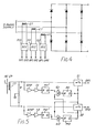
- Figures 6a and 6b show the output waveforms generated at OP1 and OP2 in response to different a.c. input waveforms.
- the circuit of Figure 5 proves to be particularly beneficial in that the open circuit arm detector of Figure 1 may be used even in circumstances when it is impracticable or inconvenient to locate current transformers in the input arm of a rectifier circuit.
Landscapes
- Engineering & Computer Science (AREA)
- Power Engineering (AREA)
- Physics & Mathematics (AREA)
- General Physics & Mathematics (AREA)
- Rectifiers (AREA)
- Measurement Of Current Or Voltage (AREA)
- Testing Of Short-Circuits, Discontinuities, Leakage, Or Incorrect Line Connections (AREA)
- Emergency Protection Circuit Devices (AREA)
Abstract
Description
- This invention relates to an electrical apparatus suitable for monitoring electrical continuity in an electrical circuit. The invention finds particular, though not exclusive, application in monitoring electrical continuity in an a.c. power supply, and especially in the rectifier circuit associated with a multi-phase power supply.
- Detection of a discontinuity in the rectifier circuit of a multi-phase power supply can be particularly important if an equipment being supplied performs a vital operational function - as in the case of equipment used in signalling or other supervisory systems, for example. A potentially hazardous situation could develop if a discontinuity occurs in one, or only some, of the input arms of the rectifier circuit since, in these circumstances, an associated equipment may continue to function, but its performance may be impaired.
- In general, an electrical apparatus used to monitor electrical continuity should be relatively insensitive to transient effects which are of little inherent interest e.g. a temporary interruption in the mains supply.
- Accordingly there is provided an electrical apparatus suitable for monitoring electrical continuity in an electrical circuit, the apparatus comprising means for generating a succession of pulses while an electrical signal prevails in the circuit and means for generating an alarm signal, to indicate an open circuit condition, if an interruption in said succession persists for at least a preset interval of time.
- In accordance with a particular embodiment of the invention the electrical apparatus includes a first timing circuit for generating a first electrical signal if said interruption persists at least for a first portion of said interval of time and a second timing signal, responsive to a said first electrical signal, to generate said alarm signal if the interruption persists for the remaining portion of said interval of time. The first and second timing circuits may include monostable circuits which have respective time constants related to said first and remaining portions of said interval of time. In a particular example, said succession of pulses has a periodicity of 20 ms and said first and remaining portions are respectivly of 70 ms and 150 ms duration. In these circumstances, the said time interval is 220 ms and so an alarm will be generated if an open circuit condition persists for a minimum of 200 ms.
- In one application of the present invention the electrical apparatus is suitable for monitoring electrical continuity in respective input arms of a rectifier circuit. In this case, a respective said pulse generating means and a respective said first timing circuit may be provided to monitor an electrical signal prevailing in each input arm of the rectifier circuit and said second timing circuit is arranged to respond to a said first electrical signal generated by any one of the first timing circuits.
- To reduce the possibility of false alarm if the rectifier circuit is de-energised intentionally, said second electrical circuit can be arranged so as to be capable of generating an alarm signal provided also that the magnitude of an electrical signal in at least one of the input arms exceeds a threshold value.
- Respective current sensing means may be provided for connection in each input arm of the rectifier circuit or, alternatively, when space is limited, current sensing means may be provided to sense current in a supply line for respective input arms of the rectifier circuit, the current sensing means including a circuit capable of responding to the positive and negative half cycles of the supply waveform to generate, at different output locations, electrical signals corresponding to the current in said respective input arms.
- In order that the invention may be carried readily into effect an embodiment thereof is now described, by way of example only, by reference to the accompanying drawings of which:
- Figure 1 shows an electrical apparatus, in accordance with the invention, which is in the form of an open circuit arm detector used to monitor electrical continuity in the rectifier circuit of a multi-phase power supply,
- Figures 2a and 2b show alternative configurations of rectifier circuit,
- Figure 3 shows an alternative form of the circuit shown in Figure 1,
- Figure 4 shows an arrangement for sensing current in the supply lines for a rectifier circuit,
- Figure 5 shows a signal conditioning circuit used in the arrangement of Figure 4, and
- Figures 6a and 6b show output waveforms generated by the conditioning circuit of Figure 5 in respect of different input waveforms.
- In this example of the present invention an open circuit arm detector, shown in Figure 1, is used to monitor electrical continuity in respective arms of a rectifier circuit.
- The rectifier circuit may be configured, as shown in Figure 2a, to receive power from a 3-phase supply or alternatively, as shown in Figure 2b, from a 6-phase, single way (half wave) supply.
- The input current ia1....ia6 prevailing in each arm A1....A6 of the rectifier circuit is monitored by means of a respective current transformer CT ....CT6. The primary winding W1 of each transformer is connected in series with a diode D1....D6 in a respective arm and a voltage, proportional to the input current in that arm, is developed across the secondary winding W2. The voltages developed in this manner are applied to respective input terminals I1 ....I6 of the detector shown in Figure 1.
- The detector operates on the received voltages and generates an alarm signal if a discontinuity in any one of the input arms persists for longer than a predetermined interval of time. If desired, the alarm signal may be used to de-energise the rectifier circuit thereby to disconnect an associated equipment which might otherwise be damaged or operate in an unreliable or dangerous manner.
- Voltages applied at input terminals I1....I6 are operated on, initially by respective circuits shown generally at 10, 20 .... 60. These circuits are identical and only one of them, circuit 10, will be described in detail.
- After amplification in a
circuit 11, a voltage applied at input terminal I1 of circuit 10 is used to drive a comparator 12. In response, the comparator generates a train of CMOS trigger pulses P which are fed to the input of anmonostable circuit 13. - In this example the trigger pulses have a periodicity of 20 ms and the monostable circuit is arranged to have a time constant of 70 ms. In these
circumstances circuit 13 assumes the unstable condition if the pulse train is applied continuously at its input. However, if an interruption of more than 70 ms occurs the circuit reverts to the stable condition and its output goes low, indicating that an open circuit condition may have arisen in the associated input arm of the rectifier circuit. - In some operational situations an interruption could arise if the rectifier circuit was de-energised intentionally; this would create an apparent "open circuit" condition in each of the input arms. To eliminate the possibility of a false alarm in these circumstances a further circuit, shown generally at 70, is provided to monitor the magnitudes of voltages applied at input terminals I1 ... 16.
- After suitable amplification, the amplitudes of the applied voltages are compared with a threshold voltage VT in a comparator 71. The threshold voltage is set at a suitable value corresponding to the minimum operating current imin in the input arms of the rectifier circuit. If the applied voltage, associated with any of the input arms, exceeds the threshold voltage VT comparator 71 generates an output signal which is fed to another
monostable circuit 72 whose input and output locations are connected to respective input terminals of aNAND gate 73. With this arrangement a low produced at the output ofgate 73 indicates that at least one of the input arms carries the minimum operating current. - The output of
gate 73 is coupled to one input terminal A of anotherNAND gate 80, the other input terminal B being coupled commonly to the outputs of themonostable circuits gate 80 are simultaneously low a potential fault detected by one or more circuits 10 .... 60 is likely to be of significance. In these circumstances the output ofgate 80 goes high and triggers a yet furthermonostable circuit 81. The input and output locations ofcircuit 81 are connected to respective input locations of afurther NAND gate 82. In this example,monostable circuit 81 has a time constant of 150 ms; if both inputs togate 80 remain low for this length of time, thereby indicating that an interruption in the pulse train, detected by one or more of circuits 10 .... 60, has persisted for 220 ms,NAND gate 82 produces an alarm signal AS suitable to cause a change of state in abistable circuit 90. Inresponse circuit 90 renders atransistor 91 non-conductive thereby causing arelay 92 to de-energise and triggering a number of alarms which may be located at remote monitoring stations. If desired, the relay may also be used to de-energise the rectifier circuit. A signal generated at the output ofbistable circuit 90 is also used to trigger alatch circuit 100 connected, as shown, to circuits 10 .... 60 so as to sample, and store data indicative of, the voltage levels prevailing at the inverted outputs ofmonostable circuits 13 .... 63. The latch, when triggered, drives appropriate ones of a plurality of transistors T1 .... T6in accordance with the stored data. If an open circuit condition is detected in an input arm of the rectifier circuit the latch drives the correspondiong transistor which, in turn, energises an associated LED (as shown). The LEDS provide a display capable, when energised, of showing the location of any detected fault. - In an alternative arrangement that part of the circuit enclosed by
box 300 in Figure 1 is replaced by a corresponding circuit shown in Figure 3. In this case,bistable circuit 90 is not used to controltransistor 91; instead alarm signal AS triggers atiming circuit 301 directly, which, in turn, de-energises the transistor, after a preset delay of 1 second, for example.Bistable circuit 90 is used to triggerlatch 100 as described hereinbefore. If desired, acapacitor 302 may be used as a "power-on-reset" for the bistable circuit. - If desired, a further relay, shown at 200 in Figure 1 may be provided which de-energises if the power supply to the circuit should fail.
- In a yet further arrangement,
monostable circuit 81 is omitted,circuits 13 .... 63 having correspondingly larger time constants (220 ms, for example), as desired. In thesecircumstances gate 80 is coupled directly tobistable circuit 90. - It will be appreciated that in some operational situations, especially when space is restricted, it may be inconvenient to provide a current transformer in each arm of the rectifier circuit, as shown in Figures 2a and 2b.
- As shown in Figure 4, it may be more convenient instead to provide respective current transformers (CT) on each input cable of the power supply. In this case half wave signals corresponding to each phase of the supply are generated at different output locations OP1, OP2 of respective
signal conditioning circuits - Referring to Figure 5, the current sensed by a transformer CT, located close to the supply line, is routed to output locations OP1, OP2 via respective solid state switching circuits S1, S2. The switching circuits are controlled by respective monostable circuits M1, M2 which are triggered by respective AND gates G1, G2. One input terminal of each gate is connected to a further monostable circuit M1', M2' which is driven by pulses generated in a comparator C1, C2 and derived from the positive and negative half cycles of the sensed current. The other input terminal of each gate Gl, G2 is cross-coupled, as shown, to the output of one of the monostable circuits M1, M2 in such a way that the switches S1, S2 can never assume the same state. In this manner the positive and negative half cycles of the a.c. input current are presented independently at the respective output locations OP1, OP2 for supply to respective input terminals of an associated continuity monitoring apparatus.
- Figures 6a and 6b show the output waveforms generated at OP1 and OP2 in response to different a.c. input waveforms.
- The circuit of Figure 5 proves to be particularly beneficial in that the open circuit arm detector of Figure 1 may be used even in circumstances when it is impracticable or inconvenient to locate current transformers in the input arm of a rectifier circuit.
- It will be appreciated that although the above-described examples involve using current transformers, alternative forms of current sensing device could be employed. For example, a Hall effect current transducer could be mounted on each input line to the rectifier circuit and interfaced with a detection circuit of the kind described, for example, by reference to Figures 1 or 3. Each transducer would generate current outputs proportional to the forward and reverse currents flowing in the line.
- It will be appreciated that although the above-described examples have been presented in the context of a three-phase or a six-phase, single-way supply the present invention is applicable to other forms of supply e.g. a single phase supply.
- Moreover, it will be understood that the present invention can be applied to other forms of electrical circuit, whether or not used for the supply of power, in respect of which it is desirable to monitor electrical continuity.
Claims (12)
Applications Claiming Priority (2)
| Application Number | Priority Date | Filing Date | Title |
|---|---|---|---|
| GB8429487 | 1984-11-22 | ||
| GB848429487A GB8429487D0 (en) | 1984-11-22 | 1984-11-22 | Electrical apparatus |
Publications (2)
| Publication Number | Publication Date |
|---|---|
| EP0187455A2 true EP0187455A2 (en) | 1986-07-16 |
| EP0187455A3 EP0187455A3 (en) | 1987-03-25 |
Family
ID=10570088
Family Applications (1)
| Application Number | Title | Priority Date | Filing Date |
|---|---|---|---|
| EP85308387A Withdrawn EP0187455A3 (en) | 1984-11-22 | 1985-11-18 | Electrical apparatus |
Country Status (6)
| Country | Link |
|---|---|
| US (1) | US4713652A (en) |
| EP (1) | EP0187455A3 (en) |
| AU (1) | AU574537B2 (en) |
| CA (1) | CA1257907A (en) |
| GB (1) | GB8429487D0 (en) |
| NZ (1) | NZ214279A (en) |
Families Citing this family (1)
| Publication number | Priority date | Publication date | Assignee | Title |
|---|---|---|---|---|
| FR2664706B1 (en) * | 1990-07-11 | 1993-02-19 | Sextant Avionique | MONITORING DEVICE FOR POLYPHASE RECTIFIER. |
Citations (2)
| Publication number | Priority date | Publication date | Assignee | Title |
|---|---|---|---|---|
| DE2317990B2 (en) * | 1972-04-28 | 1981-06-11 | Hazemeyer S.A., Saint-Quentin, Aisne | Device for detecting a phase interruption in a multi-phase system |
| DE3117284A1 (en) * | 1981-04-30 | 1982-11-25 | Siemens AG, 1000 Berlin und 8000 München | Circuit arrangement for monitoring a balanced (symmetrical) three-phase alternating current |
Family Cites Families (11)
| Publication number | Priority date | Publication date | Assignee | Title |
|---|---|---|---|---|
| US3293605A (en) * | 1966-01-20 | 1966-12-20 | Moore Laurence | Digital monitoring system |
| CH495022A (en) * | 1969-09-16 | 1970-08-15 | Cerberus Ag | Fire alarm system with a device for line monitoring |
| US3688293A (en) * | 1970-05-08 | 1972-08-29 | Standard Farrington Alarm & Si | Automatic time-controlled alarm system |
| US3728706A (en) * | 1970-09-28 | 1973-04-17 | Gen Signal Corp | System for indicating aerosols in the atmosphere |
| CA933592A (en) * | 1971-06-16 | 1973-09-11 | Canadian General Electric Company Limited | Cell surveillance monitor for a power converter |
| GB1583244A (en) * | 1977-03-31 | 1981-01-21 | British Steel Corp | Electric arc steel processing unit including apparatus for detecting broken electrodes |
| US4222037A (en) * | 1978-12-05 | 1980-09-09 | General Electric Company | Cooking cycle timer |
| US4604607A (en) * | 1979-12-27 | 1986-08-05 | Protection Products Corporation | Security device simulating currency pack or the like |
| GB2101784B (en) * | 1981-06-23 | 1985-11-27 | Chloride Group Plc | Fire alarms |
| FR2553943B1 (en) * | 1983-10-24 | 1986-04-11 | Merlin Gerin | RESIDUAL DIFFERENTIAL DEVICE PROVIDED WITH A DEVICE FOR MONITORING THE ELECTRONIC POWER SOURCE |
| FR2579159B1 (en) * | 1985-03-25 | 1987-06-26 | Nacam | DEVICE FOR ADJUSTING A STEERING COLUMN OF A MOTOR VEHICLE PROVIDED WITH KNEE LOCKING MEANS |
-
1984
- 1984-11-22 GB GB848429487A patent/GB8429487D0/en active Pending
-
1985
- 1985-11-18 EP EP85308387A patent/EP0187455A3/en not_active Withdrawn
- 1985-11-19 US US06/799,643 patent/US4713652A/en not_active Expired - Fee Related
- 1985-11-20 CA CA000495770A patent/CA1257907A/en not_active Expired
- 1985-11-20 AU AU50267/85A patent/AU574537B2/en not_active Ceased
- 1985-11-21 NZ NZ214279A patent/NZ214279A/en unknown
Patent Citations (2)
| Publication number | Priority date | Publication date | Assignee | Title |
|---|---|---|---|---|
| DE2317990B2 (en) * | 1972-04-28 | 1981-06-11 | Hazemeyer S.A., Saint-Quentin, Aisne | Device for detecting a phase interruption in a multi-phase system |
| DE3117284A1 (en) * | 1981-04-30 | 1982-11-25 | Siemens AG, 1000 Berlin und 8000 München | Circuit arrangement for monitoring a balanced (symmetrical) three-phase alternating current |
Also Published As
| Publication number | Publication date |
|---|---|
| AU574537B2 (en) | 1988-07-07 |
| US4713652A (en) | 1987-12-15 |
| GB8429487D0 (en) | 1985-01-03 |
| AU5026785A (en) | 1986-05-29 |
| CA1257907A (en) | 1989-07-25 |
| EP0187455A3 (en) | 1987-03-25 |
| NZ214279A (en) | 1988-08-30 |
Similar Documents
| Publication | Publication Date | Title |
|---|---|---|
| EP0098721A2 (en) | Differential protection relay device | |
| US4421976A (en) | System for monitoring heater elements of electric furnaces | |
| EP0708529A2 (en) | Power switch driver arrangements | |
| US4349813A (en) | Blown fuse sensor | |
| US6614217B2 (en) | Power supply negative phase detecting circuit | |
| US6999326B2 (en) | Drive controller for a self-commutated converter | |
| KR970704157A (en) | ELECTRIC VEHICLE PROPULSION SYSTEM POWER BRIDGE WITH BUILT-IN TEST WITH BUILT-IN TEST | |
| IT8322192A1 (en) | LOAD DRIVING CIRCUIT WITH LOAD CURRENT DETECTION | |
| US5552952A (en) | Detection and isolation circuit for a failed bridge power rectifier and an electrical system employing same | |
| US4713652A (en) | Electrical apparatus | |
| EP0623943B1 (en) | Relay terminal array with malfunction detection and transmission functions | |
| US6111736A (en) | Static relay with condition detecting | |
| US11762039B2 (en) | Electrical installation comprising a monitoring module | |
| US4380045A (en) | Thyristor convertor failure detection device | |
| US3968477A (en) | Control apparatus for electrical devices | |
| US11914002B2 (en) | Electrical installation comprising a monitoring module | |
| KR970010609B1 (en) | Apparatus for detection and alarm of overload of transformer | |
| US4628244A (en) | Electrical indicating circuit | |
| RU2109302C1 (en) | Device for checking of n alternating currents | |
| SU1317558A1 (en) | Device with protection unit for supplying power to d.c.using equipment | |
| SU1480001A1 (en) | Device for detection of single-phase partial ground in three-phase network with insulated neutral | |
| US3914664A (en) | Voltage balance relay | |
| SU1043779A1 (en) | Apparatus for differentiatial protection of generator | |
| KR20040009973A (en) | Voltage Dip dictecting system of an alternating current supplied to PLC | |
| SU951534A1 (en) | Voltage indicator |
Legal Events
| Date | Code | Title | Description |
|---|---|---|---|
| PUAI | Public reference made under article 153(3) epc to a published international application that has entered the european phase |
Free format text: ORIGINAL CODE: 0009012 |
|
| AK | Designated contracting states |
Kind code of ref document: A2 Designated state(s): AT BE CH DE FR GB IT LI LU NL SE |
|
| PUAL | Search report despatched |
Free format text: ORIGINAL CODE: 0009013 |
|
| AK | Designated contracting states |
Kind code of ref document: A3 Designated state(s): AT BE CH DE FR GB IT LI LU NL SE |
|
| 17P | Request for examination filed |
Effective date: 19871009 |
|
| 17Q | First examination report despatched |
Effective date: 19900115 |
|
| STAA | Information on the status of an ep patent application or granted ep patent |
Free format text: STATUS: THE APPLICATION HAS BEEN WITHDRAWN |
|
| 18W | Application withdrawn |
Withdrawal date: 19911202 |
|
| R18W | Application withdrawn (corrected) |
Effective date: 19911202 |
|
| RIN1 | Information on inventor provided before grant (corrected) |
Inventor name: FRENCH, STEVEN JOHN Inventor name: NEASHAM, DAVID LYNN |