EP0187432B1 - Aftertreatment of distilled water - Google Patents
Aftertreatment of distilled water Download PDFInfo
- Publication number
- EP0187432B1 EP0187432B1 EP85300177A EP85300177A EP0187432B1 EP 0187432 B1 EP0187432 B1 EP 0187432B1 EP 85300177 A EP85300177 A EP 85300177A EP 85300177 A EP85300177 A EP 85300177A EP 0187432 B1 EP0187432 B1 EP 0187432B1
- Authority
- EP
- European Patent Office
- Prior art keywords
- carbon dioxide
- water
- evaporator
- sea water
- distilled water
- Prior art date
- Legal status (The legal status is an assumption and is not a legal conclusion. Google has not performed a legal analysis and makes no representation as to the accuracy of the status listed.)
- Expired - Lifetime
Links
- XLYOFNOQVPJJNP-UHFFFAOYSA-N water Chemical compound O XLYOFNOQVPJJNP-UHFFFAOYSA-N 0.000 title claims description 56
- 239000012153 distilled water Substances 0.000 title claims description 33
- CURLTUGMZLYLDI-UHFFFAOYSA-N Carbon dioxide Chemical compound O=C=O CURLTUGMZLYLDI-UHFFFAOYSA-N 0.000 claims description 141
- 239000001569 carbon dioxide Substances 0.000 claims description 70
- 229910002092 carbon dioxide Inorganic materials 0.000 claims description 70
- 239000013535 sea water Substances 0.000 claims description 54
- 238000001704 evaporation Methods 0.000 claims description 34
- 230000008020 evaporation Effects 0.000 claims description 34
- 238000000034 method Methods 0.000 claims description 24
- 238000007789 sealing Methods 0.000 claims description 19
- 230000000694 effects Effects 0.000 claims description 18
- 238000011144 upstream manufacturing Methods 0.000 claims description 6
- 239000000203 mixture Substances 0.000 claims description 5
- 239000013505 freshwater Substances 0.000 claims description 3
- 238000004090 dissolution Methods 0.000 claims description 2
- 238000004821 distillation Methods 0.000 claims description 2
- 239000012223 aqueous fraction Substances 0.000 claims 3
- 238000000926 separation method Methods 0.000 claims 1
- 239000007789 gas Substances 0.000 description 17
- 238000010612 desalination reaction Methods 0.000 description 11
- VTYYLEPIZMXCLO-UHFFFAOYSA-L Calcium carbonate Chemical compound [Ca+2].[O-]C([O-])=O VTYYLEPIZMXCLO-UHFFFAOYSA-L 0.000 description 8
- 238000010438 heat treatment Methods 0.000 description 7
- 239000003795 chemical substances by application Substances 0.000 description 6
- 239000002253 acid Substances 0.000 description 5
- 229910000019 calcium carbonate Inorganic materials 0.000 description 4
- QGZKDVFQNNGYKY-UHFFFAOYSA-N Ammonia Chemical compound N QGZKDVFQNNGYKY-UHFFFAOYSA-N 0.000 description 3
- 230000008901 benefit Effects 0.000 description 3
- 239000012267 brine Substances 0.000 description 3
- AXCZMVOFGPJBDE-UHFFFAOYSA-L calcium dihydroxide Chemical compound [OH-].[OH-].[Ca+2] AXCZMVOFGPJBDE-UHFFFAOYSA-L 0.000 description 3
- 239000000920 calcium hydroxide Substances 0.000 description 3
- 229910001861 calcium hydroxide Inorganic materials 0.000 description 3
- 235000011116 calcium hydroxide Nutrition 0.000 description 3
- 238000010586 diagram Methods 0.000 description 3
- HPALAKNZSZLMCH-UHFFFAOYSA-M sodium;chloride;hydrate Chemical compound O.[Na+].[Cl-] HPALAKNZSZLMCH-UHFFFAOYSA-M 0.000 description 3
- OYPRJOBELJOOCE-UHFFFAOYSA-N Calcium Chemical compound [Ca] OYPRJOBELJOOCE-UHFFFAOYSA-N 0.000 description 2
- OAKJQQAXSVQMHS-UHFFFAOYSA-N Hydrazine Chemical compound NN OAKJQQAXSVQMHS-UHFFFAOYSA-N 0.000 description 2
- 239000011575 calcium Substances 0.000 description 2
- 229910052791 calcium Inorganic materials 0.000 description 2
- 238000007796 conventional method Methods 0.000 description 2
- 239000000498 cooling water Substances 0.000 description 2
- 238000000605 extraction Methods 0.000 description 2
- 238000010079 rubber tapping Methods 0.000 description 2
- 150000003839 salts Chemical class 0.000 description 2
- BVKZGUZCCUSVTD-UHFFFAOYSA-L Carbonate Chemical compound [O-]C([O-])=O BVKZGUZCCUSVTD-UHFFFAOYSA-L 0.000 description 1
- 238000013019 agitation Methods 0.000 description 1
- XKMRRTOUMJRJIA-UHFFFAOYSA-N ammonia nh3 Chemical compound N.N XKMRRTOUMJRJIA-UHFFFAOYSA-N 0.000 description 1
- -1 bicarbonate (HCO - 3 ) ions Chemical class 0.000 description 1
- 230000015572 biosynthetic process Effects 0.000 description 1
- 235000010216 calcium carbonate Nutrition 0.000 description 1
- 238000011109 contamination Methods 0.000 description 1
- 238000001816 cooling Methods 0.000 description 1
- 238000005260 corrosion Methods 0.000 description 1
- 230000007797 corrosion Effects 0.000 description 1
- 239000003651 drinking water Substances 0.000 description 1
- 235000020188 drinking water Nutrition 0.000 description 1
- 239000002737 fuel gas Substances 0.000 description 1
- 239000000295 fuel oil Substances 0.000 description 1
- 229910052500 inorganic mineral Inorganic materials 0.000 description 1
- 239000011707 mineral Substances 0.000 description 1
- 235000010755 mineral Nutrition 0.000 description 1
- 239000001205 polyphosphate Substances 0.000 description 1
- 235000011176 polyphosphates Nutrition 0.000 description 1
- 230000000135 prohibitive effect Effects 0.000 description 1
- 238000000197 pyrolysis Methods 0.000 description 1
- 239000000243 solution Substances 0.000 description 1
Images
Classifications
-
- C—CHEMISTRY; METALLURGY
- C02—TREATMENT OF WATER, WASTE WATER, SEWAGE, OR SLUDGE
- C02F—TREATMENT OF WATER, WASTE WATER, SEWAGE, OR SLUDGE
- C02F1/00—Treatment of water, waste water, or sewage
- C02F1/68—Treatment of water, waste water, or sewage by addition of specified substances, e.g. trace elements, for ameliorating potable water
-
- C—CHEMISTRY; METALLURGY
- C02—TREATMENT OF WATER, WASTE WATER, SEWAGE, OR SLUDGE
- C02F—TREATMENT OF WATER, WASTE WATER, SEWAGE, OR SLUDGE
- C02F1/00—Treatment of water, waste water, or sewage
-
- C—CHEMISTRY; METALLURGY
- C02—TREATMENT OF WATER, WASTE WATER, SEWAGE, OR SLUDGE
- C02F—TREATMENT OF WATER, WASTE WATER, SEWAGE, OR SLUDGE
- C02F1/00—Treatment of water, waste water, or sewage
- C02F1/02—Treatment of water, waste water, or sewage by heating
- C02F1/04—Treatment of water, waste water, or sewage by heating by distillation or evaporation
- C02F1/042—Prevention of deposits
-
- Y—GENERAL TAGGING OF NEW TECHNOLOGICAL DEVELOPMENTS; GENERAL TAGGING OF CROSS-SECTIONAL TECHNOLOGIES SPANNING OVER SEVERAL SECTIONS OF THE IPC; TECHNICAL SUBJECTS COVERED BY FORMER USPC CROSS-REFERENCE ART COLLECTIONS [XRACs] AND DIGESTS
- Y02—TECHNOLOGIES OR APPLICATIONS FOR MITIGATION OR ADAPTATION AGAINST CLIMATE CHANGE
- Y02A—TECHNOLOGIES FOR ADAPTATION TO CLIMATE CHANGE
- Y02A20/00—Water conservation; Efficient water supply; Efficient water use
- Y02A20/124—Water desalination
Definitions
- This invention relates generally to a method for treating the distilled water obtained from an evaporation process sea water desalination plant.
- the distilled water obtained as a result of evaporation desalination processes is devoid of minerals, leading to the corrosion of water handling apparatus and lacking taste as drinking water.
- a solution to the problem has been to convert the distilled water to a more suitable quality by dissolving carbon dioxide and calcium carbonate or calcium hydroxide into the distilled water.
- the expense of obtaining the quantity of carbon dioxide necessary to treat the water has been a disadvantage, however.
- ammonia gas resulting from pyrolysis of hydrazine from the use of deoxidizers typically found in high pressure steam systems may ultimately contaminate, with unacceptable levels of ammonia nitrogen, the distilled water to which carbon dioxide generated from this method is added.
- DE-A-1 955 571 there is a proposal to dissolve in distilled water produced by a multiple effect evaporator carbon dioxide generated from the sea water feed, but that proposal contemplates liberation of the CO2 from sea water upstream of the evaporator, such as by the addition of acid.
- DE-A-2 725 010 there is a further proposal to absorb carbon dioxide in the distilled water product from a flash evaporator and it is suggested that the carbon dioxide can be obtained by known methods such as the addition of acid or flash evaporation but the disclosure is otherwise silent as to how or where that is to be done.
- a method of obtaining potable distilled water by the multi-stage or multiple effect evaporation of sea water wherein carbon dioxide generated from the sea water passing through the evaporator is dissolved in the final distillate, characterised in that the carbon dioxide is extracted from the sea water after it has already been preheated in the same evaporator as that in which the sea water is distilled, from at least one chamber of said evaporator in which the temperature of the sea water is above 60°C.
- the invention further provides an apparatus for obtaining potable distilled water, comprising a multi-stage or multiple effect evaporator for the distillation of sea water, said evaporator having a succession of chambers including means for preheating the sea water feed entering the evaporator; and means for dissolution in the product distilled water of carbon dioxide also generated from sea water, characterised by means for extracting said carbon dioxide gas from chambers of the same evaporator as is used for distilling the sea water which chambers lie downstream of the evaporator sea water preheating means and in which during operation the temperature of the sea water is above 60°C.
- the equipment shown includes a brine heater 1, multiple evaporation stages 2 and an antiscale agent feeder 3.
- Each evaporation stage 2 has an evaporation chamber 4 and a condenser 5.
- Sea water is supplied into the system through a pipe 6 and an antiscale agent is added through the antiscale agent feeder 3.
- Antiscale agents such as poly-phosphate, inhibit scale formation during the evaporation process.
- the sea water then flows sequentially from the lowest temperature evaporation stage to the highest temperature evaporation stage within the tubes of the condensers 5 of each evaporation chamber 4, the sea water being heated progressively by the vapor generated in each evaporation stage.
- the sea water is further heated in the brine heater 1 by high temperature steam supplied from, for example, a boiler through the pipe 7.
- the heated sea water is then fed back through the evaporation chambers 4,from the highest to the lowest evaporation stage, for flash evaporation. After the flash evaporation process, the unevaporated portion of the sea water is discharged out of the system through a pipe 8 from the final lowest temperature evaporation stage.
- each evaporation chamber 4 is maintained at a specific degree of vacuum by vacuum equipment such as steam ejector 17 connected to the lowest temperature evaporation chamber, although the pressure in the highest temperature evaporation chamber may be close to or even higher than atmospheric pressure.
- each evaporation stage is condensed on the outsides of the tubes of the respective condenser 5 to become distilled water, which is collected and discharged out of the system via calcium carbonate dissolving equipment 10 through a pipe 9.
- sea water contains carbonate ions (CO -- 3 ) and carbonic acid, typically 140 ppm, as bicarbonate (HCO - 3 ) ions which, when heated, decompose to produce carbon dioxide (CO2) in various ways, such as the following:- 2HCO - 3 ⁇ CO -- 3 +H2O+CO2 ⁇ CO -- 3 +H2O ⁇ 2OH ⁇ +CO2 ⁇
- CO2 carbonate ions
- HCO - 3 bicarbonate
- the carbon dioxide thus produced is extracted together with other noncondensing gases from the two highest temperature evaporation chambers 4 and fed to a pipe 11.
- the carbon dioxide gas mixture is compressed in a water-sealed compressor 13 and delivered into a separator 14.
- the mixture is separated into gases containing carbon dioxide and compressor sealing water in which a significant amount of carbon dioxide will be dissolved.
- the gases containing carbon dioxide and the sealing water in which carbon dioxide is dissolved are supplied into the pipe 9 delivering the product distilled water, through pipes 16 and 15, respectively.
- the sealing water of the water-sealed compressor 13 may be supplied through pipe 32 with distilled water pumped by a pump 33 from upstream of the introduction of carbon dioxide into the distilled water product line through pipes 15 and 16.
- fresh water may instead be used as sealing water and changeover valves are provided so that this may be supplied through pipe 34.
- a vent ejector for generating high vacuum is not particularly needed to extract the noncondensing gases including carbon dioxide from these evaporation chambers. If a vent ejector is used, a small one requiring little steam consumption is sufficient.
- the sealing water and gases containing carbon dioxide from the separator 14 When feeding the sealing water and gases containing carbon dioxide from the separator 14 into the delivery pipe 9 for the distilled water, it is preferable to supply the sealing water from the separator 14 through the pipe 15 downstream of the supply of the gases containing carbon dioxide through the pipe 16. If reversed, the volume of carbon dioxide gas dissolving into the distilled water would be lowered due to the presence of carbon dioxide supplied from the carbon dioxide dissolved in the sealing water. The carbon dioxide in the sealing water has, of course, already been effectively dissolved therein by the pressure and agitation in the compressor itself.
- the quantity of calcium dissolving may be increased by providing the dissolving equipment 10 downstream of the supply points of the carbon dioxide through pipes 15 and 16.
- FIG. 2 shows a flow diagram of the method as applied to a conventional multiple-effect type sea water desalination plant.
- Sea water is supplied into the system through pipe 18, and an antiscale agent is added through the antiscale agent feeder 3.
- the sea water flows from the lowest temperature stage to the highest temperature stage sequentially within the tubes of the preheater 20 of the evaporation tower 35, during which it is heated.
- the heated sea water is then sprayed over the outer surfaces of the heating tubes 22 of the first effect evaporator stage 21, and is partially evaporated by heat provided from steam supplied into the heating tubes 22 through pipe 23.
- the remaining unevaporated sea water is sprayed over the outer surfaces of the heating tubes 25 of the second effect evaporator stage 24.
- the remaining unevaporated sea water descends through the lower stages of the multiple effect evaporator tower and is discharged out of the system through a pipe 27 from the final effect evaporator stage 26.
- the vapor generated in the first effect evaporator stage 21 is supplied into the heating tubes of the second effect evaporator stage 24, and is condensed as the cooler sea water is sprayed over the outer surfaces of the heating tubes 25. Thereafter, the same action is repeated sequentially in each evaporator effect until the steam generated in the final effect evaporator stage 26 is cooled and condensed at the bottom of the tower in a condenser 28 by sea water flowing in the cooling tubes 29 of the condenser 28.
- This condensate is combined with the condensates from all the heating tubes of all the evaporator effects and is discharged out of the system as product distilled water through the delivery pipe 30 which feeds it to the calcium carbonate dissolving equipment 10.
- Carbon dioxide together with other noncondensing gases is extracted through the tube 11 from gas tapping connections at the upper part of the evaporator tower where the temperature of the sea water is higher than 60 o C; these gas tappings may withdraw gas that has been generated in the first and second effect evaporator stages 21 and 24.
- the carbon dioxide is compressed by compressor 13 of the same water sealed type as in Fig. 1. The mixture is then fed into the separator 14.
- the resulting carbon dioxide gas and sealing water containing dissolved carbon dioxide are supplied into the distilled water delivery pipe 30 through the pipes 16 and 15.
- a gas separator 31 indicated by chain lines, may be disposed immediately at the downstream side of the brine heater 11 in the multi-stage flash type desalination plant shown in Fig. 1, or immediately at the downstream side of the preheater 20 in the multiple-effect type desalination plant shown in Fig. 2.
- carbon dioxide may be separated, together with other noncondensing gases, from the high temperature sea water in this gas separator 31 and may then be supplied to the pipe 11.
- the load on the vacuum equipment for keeping the evaporation chambers under partial vacuum may be lessened advantageously.
- the carbon dioxide generated from the high temperature sea water is compressed by a water-sealed compressor, and is supplied into the distilled water together with the compressor sealing water.
Landscapes
- Chemical & Material Sciences (AREA)
- Life Sciences & Earth Sciences (AREA)
- Hydrology & Water Resources (AREA)
- Engineering & Computer Science (AREA)
- Environmental & Geological Engineering (AREA)
- Water Supply & Treatment (AREA)
- Organic Chemistry (AREA)
- Health & Medical Sciences (AREA)
- Medicinal Chemistry (AREA)
- Heat Treatment Of Water, Waste Water Or Sewage (AREA)
- Vaporization, Distillation, Condensation, Sublimation, And Cold Traps (AREA)
- Treating Waste Gases (AREA)
Description
- This invention relates generally to a method for treating the distilled water obtained from an evaporation process sea water desalination plant.
- Typically, the distilled water obtained as a result of evaporation desalination processes is devoid of minerals, leading to the corrosion of water handling apparatus and lacking taste as drinking water. A solution to the problem has been to convert the distilled water to a more suitable quality by dissolving carbon dioxide and calcium carbonate or calcium hydroxide into the distilled water. The expense of obtaining the quantity of carbon dioxide necessary to treat the water has been a disadvantage, however.
- Conventionally, carbon dioxide has been produced utilizing processes unrelated to that of the desalination plant by burning fuel oil or fuel gas. The enormous expense and running costs of such a separate facility are, however, prohibitive.
- An improvement on the conventional method of producing carbon dioxide shown in Japanese Patent Provisional Publication No. 55-35971, makes use of the phenomenon that carbon dioxide is generated when acid such as hydrochloric or sulfuric is added to salt water. Before beginning the desalination process, acid is added to the salt water which is then fed into a decarbonator. Carbon dioxide is extracted from the decarbonator, which is at high vacuum (about -600mmHg), with a vent ejector, requiring a large quantity of high pressure steam. The steam must then be condensed out, requiring a large quantity of cooling water. Although this method is an improvement over the conventional method of generating carbon dioxide in a completely separate process, the large quantities of steam and cooling water required by this method are disadvantageous. In addition, ammonia gas resulting from pyrolysis of hydrazine from the use of deoxidizers typically found in high pressure steam systems may ultimately contaminate, with unacceptable levels of ammonia nitrogen, the distilled water to which carbon dioxide generated from this method is added.
- Likewise in DE-A-1 955 571 there is a proposal to dissolve in distilled water produced by a multiple effect evaporator carbon dioxide generated from the sea water feed, but that proposal contemplates liberation of the CO₂ from sea water upstream of the evaporator, such as by the addition of acid. In DE-A-2 725 010 there is a further proposal to absorb carbon dioxide in the distilled water product from a flash evaporator and it is suggested that the carbon dioxide can be obtained by known methods such as the addition of acid or flash evaporation but the disclosure is otherwise silent as to how or where that is to be done.
- It is therefore an object of the present invention to achieve a process that is advantageously improved over the prior art processes and in which, in particular, the need to add costly and corrosive acid to liberate the carbon dioxide is entirely eliminated.
- According to the invention, there is provided a method of obtaining potable distilled water by the multi-stage or multiple effect evaporation of sea water, wherein carbon dioxide generated from the sea water passing through the evaporator is dissolved in the final distillate, characterised in that the carbon dioxide is extracted from the sea water after it has already been preheated in the same evaporator as that in which the sea water is distilled, from at least one chamber of said evaporator in which the temperature of the sea water is above 60°C.
- The invention further provides an apparatus for obtaining potable distilled water, comprising a multi-stage or multiple effect evaporator for the distillation of sea water, said evaporator having a succession of chambers including means for preheating the sea water feed entering the evaporator; and means for dissolution in the product distilled water of carbon dioxide also generated from sea water, characterised by means for extracting said carbon dioxide gas from chambers of the same evaporator as is used for distilling the sea water which chambers lie downstream of the evaporator sea water preheating means and in which during operation the temperature of the sea water is above 60°C.
- The invention together with further aspects and advantages thereof, may best be understood, however, by reference to the following description taken in conjunction with the accompanying drawings in which:
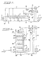
- Fig. 1 is a flow diagram of a method according to the invention as applied to a conventionally known multiple-stage flash type sea water desalination process; and
- Fig. 2 is a flow diagram of a method according to the invention as applied to a conventionally known multiple-effect type sea water desalination process.
- Referring first to Figure 1, the equipment shown includes a brine heater 1,
multiple evaporation stages 2 and anantiscale agent feeder 3. Eachevaporation stage 2 has an evaporation chamber 4 and acondenser 5. - Sea water is supplied into the system through a pipe 6 and an antiscale agent is added through the
antiscale agent feeder 3. Antiscale agents, such as poly-phosphate, inhibit scale formation during the evaporation process. The sea water then flows sequentially from the lowest temperature evaporation stage to the highest temperature evaporation stage within the tubes of thecondensers 5 of each evaporation chamber 4, the sea water being heated progressively by the vapor generated in each evaporation stage. The sea water is further heated in the brine heater 1 by high temperature steam supplied from, for example, a boiler through the pipe 7. The heated sea water is then fed back through the evaporation chambers 4,from the highest to the lowest evaporation stage, for flash evaporation. After the flash evaporation process, the unevaporated portion of the sea water is discharged out of the system through apipe 8 from the final lowest temperature evaporation stage. - The inside of each evaporation chamber 4 is maintained at a specific degree of vacuum by vacuum equipment such as
steam ejector 17 connected to the lowest temperature evaporation chamber, although the pressure in the highest temperature evaporation chamber may be close to or even higher than atmospheric pressure. - The vapor generated in each evaporation stage is condensed on the outsides of the tubes of the
respective condenser 5 to become distilled water, which is collected and discharged out of the system via calciumcarbonate dissolving equipment 10 through a pipe 9. - During the evaporation process, a huge volume of carbon dioxide is produced in the higher
temperature evaporation stages 2 due to the high temperature of the sea water in these stages. This result is obtained because sea water contains carbonate ions (CO


The output of carbon dioxide increases with increase in the temperature of the sea water. - In the plant shown, the carbon dioxide thus produced is extracted together with other noncondensing gases from the two highest temperature evaporation chambers 4 and fed to a pipe 11. After removal of condensate in a
condenser 12, the carbon dioxide gas mixture is compressed in a water-sealedcompressor 13 and delivered into aseparator 14. The mixture is separated into gases containing carbon dioxide and compressor sealing water in which a significant amount of carbon dioxide will be dissolved. The gases containing carbon dioxide and the sealing water in which carbon dioxide is dissolved are supplied into the pipe 9 delivering the product distilled water, throughpipes - The sealing water of the water-sealed
compressor 13 may be supplied throughpipe 32 with distilled water pumped by apump 33 from upstream of the introduction of carbon dioxide into the distilled water product line throughpipes pipe 34. - Because the pressure in the higher temperature evaporation chambers is close to or higher than atmospheric pressure, and because the concentration of the carbon dioxide generated in the higher temperature evaporation chambers is high, a vent ejector for generating high vacuum is not particularly needed to extract the noncondensing gases including carbon dioxide from these evaporation chambers. If a vent ejector is used, a small one requiring little steam consumption is sufficient.
- Because the volume of carbon dioxide produced by heating the sea water suddenly increases when exceeding 60oC, the carbon dioxide is extracted from those chambers of the evaporator in which the sea water is at a temperature above 60oC.
- When feeding the sealing water and gases containing carbon dioxide from the
separator 14 into the delivery pipe 9 for the distilled water, it is preferable to supply the sealing water from theseparator 14 through thepipe 15 downstream of the supply of the gases containing carbon dioxide through thepipe 16. If reversed, the volume of carbon dioxide gas dissolving into the distilled water would be lowered due to the presence of carbon dioxide supplied from the carbon dioxide dissolved in the sealing water. The carbon dioxide in the sealing water has, of course, already been effectively dissolved therein by the pressure and agitation in the compressor itself. - When dissolving calcium into the distilled water, using calcium carbonate, calcium hydroxide or slaked lime, the quantity of calcium dissolving may be increased by providing the dissolving
equipment 10 downstream of the supply points of the carbon dioxide throughpipes - Reference will now be made to Fig. 2 which shows a flow diagram of the method as applied to a conventional multiple-effect type sea water desalination plant.
- Sea water is supplied into the system through
pipe 18, and an antiscale agent is added through theantiscale agent feeder 3. The sea water flows from the lowest temperature stage to the highest temperature stage sequentially within the tubes of thepreheater 20 of theevaporation tower 35, during which it is heated. The heated sea water is then sprayed over the outer surfaces of theheating tubes 22 of the firsteffect evaporator stage 21, and is partially evaporated by heat provided from steam supplied into theheating tubes 22 throughpipe 23. The remaining unevaporated sea water is sprayed over the outer surfaces of theheating tubes 25 of the secondeffect evaporator stage 24. In a similar manner, the remaining unevaporated sea water descends through the lower stages of the multiple effect evaporator tower and is discharged out of the system through apipe 27 from the finaleffect evaporator stage 26. - The vapor generated in the first
effect evaporator stage 21 is supplied into the heating tubes of the secondeffect evaporator stage 24, and is condensed as the cooler sea water is sprayed over the outer surfaces of theheating tubes 25. Thereafter, the same action is repeated sequentially in each evaporator effect until the steam generated in the finaleffect evaporator stage 26 is cooled and condensed at the bottom of the tower in acondenser 28 by sea water flowing in thecooling tubes 29 of thecondenser 28. This condensate is combined with the condensates from all the heating tubes of all the evaporator effects and is discharged out of the system as product distilled water through thedelivery pipe 30 which feeds it to the calciumcarbonate dissolving equipment 10. - Carbon dioxide together with other noncondensing gases is extracted through the tube 11 from gas tapping connections at the upper part of the evaporator tower where the temperature of the sea water is higher than 60oC; these gas tappings may withdraw gas that has been generated in the first and second
effect evaporator stages condenser 12, the carbon dioxide is compressed bycompressor 13 of the same water sealed type as in Fig. 1. The mixture is then fed into theseparator 14. The resulting carbon dioxide gas and sealing water containing dissolved carbon dioxide are supplied into the distilledwater delivery pipe 30 through thepipes - The method as described above shows the extraction of carbon dioxide from the higher temperature evaporation stages of the desalination process. As an alternative, a
gas separator 31, indicated by chain lines, may be disposed immediately at the downstream side of the brine heater 11 in the multi-stage flash type desalination plant shown in Fig. 1, or immediately at the downstream side of thepreheater 20 in the multiple-effect type desalination plant shown in Fig. 2. Thus, carbon dioxide may be separated, together with other noncondensing gases, from the high temperature sea water in thisgas separator 31 and may then be supplied to the pipe 11. When carbon dioxide is separated from the high temperature sea water before its entry into the evaporation stages, the load on the vacuum equipment for keeping the evaporation chambers under partial vacuum may be lessened advantageously. - Since carbon dioxide at high concentrations is produced from the sea water in the higher temperature stages of the desalination plant, it can be extracted without a high vacuum. Thus, the diameter of the piping for feeding the carbon dioxide into the distilled water may be reduced, and the vent ejector employed in the prior art which consumes a huge volume of steam for extraction is not particularly required. Nor is an enclosed type decarbonator required. As a result, the facility may be downsized at reduced cost, and the running cost may be considerably reduced at the same time. Since boiler steam is not necessary to extract the carbon dioxide, ammonia gas contamination of the distilled water is not a problem. However, if a vent ejector is used, a small one consuming little steam is sufficient, with the benefit that the quantity of ammonia gas in the steam will still not significantly contaminate the distilled water.
- The carbon dioxide generated from the high temperature sea water is compressed by a water-sealed compressor, and is supplied into the distilled water together with the compressor sealing water. This is a further advantage of the method described because, when compressing in a water-sealed compressor, carbon dioxide can be dissolved to a significant extent in the sealing water in the compressor, and thus the ultimate volume of dissolved carbon dioxide in the distilled water is increased.
Claims (10)
- A method of obtaining potable distilled water, by the multi-stage or multiple effect evaporation of sea water, wherein carbon dioxide generated from the sea water passing through the evaporator is dissolved in the final distillate, characterised in that the carbon dioxide is extracted from the sea water after it has already been preheated in the same evaporator as that in which the sea water is distilled, from at least one chamber of said evaporator in which the temperature of the sea water is above 60°C.
- A method according to claim 1, wherein the carbon dioxide is extracted, at least in part, from one or more of the higher temperature stages or effects of the multi-stage or multiple effect evaporator.
- A method according to Claim 1 or Claim 2, wherein the carbon dioxide is extracted, at least in part, from a separator chamber situated downstream of the sea water preheating means of the evaporator and upstream of the evaporation chambers.
- A method according to Claim 1 or Claim 2 or Claim 3, wherein the extracted carbon dioxide is compressed in a water-sealed compressor sealed by fresh or distilled water whereby the action of the compressor dissolves carbon dioxide in the sealing water which is then added to the distilled water product from the evaporator.
- A method according to Claim 4, wherein the carbon dioxide and sealing water mixture from the compressor is passed to a separator, from which the sealing water fraction is fed into the product distilled water and the carbon dioxide gas fraction is also fed into the product distilled water at a point upstream of the feed point of the sealing water fraction.
- Apparatus for obtaining potable distilled water, comprising a multi-stage or multiple effect evaporator for the distillation of sea water, said evaporator having a succession of chambers including means for preheating the sea water feed entering the evaporator; and means for dissolution in the product distilled water of carbon dioxide also generated from sea water, characterised by means (11,13) for extracting said carbon dioxide gas from chambers (4;21,24,31) of the same evaporator (2,19) as is used for distilling the sea water which chambers lie downstream of the evaporator sea water preheating means (1,5;20) and in which during operation the temperature of the sea water is above 60°C.
- Apparatus according to Claim 6, wherein at least a portion of the carbon dioxide is extracted from one or more of the higher temperature stages or effects (4;21,24) of the evaporator.
- Apparatus according to Claim 6 or Claim 7, wherein at least a portion of the carbon dioxide is extracted from a separation chamber (31) provided downstream of the evaporator sea water preheating means and upstream of the sea water evaporation chambers.
- Apparatus according to any preceding claim, including a water-sealed compressor (13), sealed with fresh or distilled water, in which the extracted carbon dioxide is compressed, the action of the compressor causing a portion of the carbon dioxide to become dissolved in the compressor sealing water which is then introduced into the product distillate line (9, 30) from the evaporator.
- Apparatus according to Claim 9, wherein the carbon dioxide gas and sealing water mixture from the compressor is delivered into a separator (14), from which the sealing water fraction is delivered to the product line (9, 30) through one line (15) and the carbon dioxide gas fraction is delivered to the product line through a separate line (16) which feeds into the product line upstream of the feeding-in point of the sealing water line.
Priority Applications (3)
| Application Number | Priority Date | Filing Date | Title |
|---|---|---|---|
| FR858500271A FR2575742B1 (en) | 1985-01-10 | 1985-01-09 | PROCESS FOR AFTER-TREATMENT OF DISTILLED WATER, BY DISSOLUTION OF CALCIUM AND CARBON DIOXIDE IN DISTILLED WATER OBTAINED IN AN EVAPORATIVE DESALINATION PLANT |
| EP85300177A EP0187432B1 (en) | 1985-01-10 | 1985-01-10 | Aftertreatment of distilled water |
| DE8585300177T DE3583798D1 (en) | 1985-01-10 | 1985-01-10 | POST-TREATMENT OF DISTILLED WATER. |
Applications Claiming Priority (1)
| Application Number | Priority Date | Filing Date | Title |
|---|---|---|---|
| EP85300177A EP0187432B1 (en) | 1985-01-10 | 1985-01-10 | Aftertreatment of distilled water |
Publications (2)
| Publication Number | Publication Date |
|---|---|
| EP0187432A1 EP0187432A1 (en) | 1986-07-16 |
| EP0187432B1 true EP0187432B1 (en) | 1991-08-14 |
Family
ID=8194113
Family Applications (1)
| Application Number | Title | Priority Date | Filing Date |
|---|---|---|---|
| EP85300177A Expired - Lifetime EP0187432B1 (en) | 1985-01-10 | 1985-01-10 | Aftertreatment of distilled water |
Country Status (3)
| Country | Link |
|---|---|
| EP (1) | EP0187432B1 (en) |
| DE (1) | DE3583798D1 (en) |
| FR (1) | FR2575742B1 (en) |
Families Citing this family (9)
| Publication number | Priority date | Publication date | Assignee | Title |
|---|---|---|---|---|
| GB2256639A (en) * | 1991-06-13 | 1992-12-16 | York Nutritional Lab | Improvements relating to liquids |
| GB9113971D0 (en) * | 1991-06-28 | 1991-08-14 | Boc Group Plc | Treatment of water |
| IL147222A0 (en) * | 1999-06-25 | 2002-08-14 | Abiogen Pharma Spa | Preparation and metering of components with co2 |
| FR2810506B1 (en) * | 2000-06-21 | 2002-09-27 | Gervais Danone Sa | PROCESS FOR PRODUCING CALCIUM-RICH WATER AND WATER OBTAINED BY THIS PROCESS |
| ES2259562B1 (en) * | 2005-03-23 | 2008-03-01 | Pridesa Proyectos Y Servicios, S.A.U. | SYSTEM FOR PREPARATION AND DOSAGE IN CONTINUOUS CALCIUM HYDROXIDE FOR WATER REMINERALIZATION SYSTEMS APPLIED TO WATER DESALATING PLANTS. |
| EP2418177B9 (en) | 2010-08-13 | 2015-09-16 | Omya International AG | Micronized CaCO3 slurry injection system for the remineralization of desalinated and fresh water |
| ITUB20154766A1 (en) * | 2015-11-03 | 2017-05-03 | Fisia Italimpianti S P A | Recharging plant for a mixture of distilled water from thermal and permeation desalination plants from reverse osmosis desalination plants |
| ITUB20155252A1 (en) * | 2015-11-03 | 2017-05-03 | Fisia Italimpianti S P A | Recharge plant for distilled and / or permeate water using calcium carbonate reactors and injection of carbon dioxide and strong acids |
| CN111252979A (en) * | 2020-01-14 | 2020-06-09 | 自然资源部天津海水淡化与综合利用研究所 | Thermal method seawater desalination water post-treatment system for municipal water supply |
Family Cites Families (2)
| Publication number | Priority date | Publication date | Assignee | Title |
|---|---|---|---|---|
| DE1955571A1 (en) * | 1969-11-05 | 1971-05-13 | Metallgesellschaft Ag | Hardening of distilled water |
| NL7605952A (en) * | 1976-06-02 | 1977-12-06 | Curacao Eilandgebied | METHOD AND EQUIPMENT FOR TREATING SEA AND FRESHWATER. |
-
1985
- 1985-01-09 FR FR858500271A patent/FR2575742B1/en not_active Expired - Fee Related
- 1985-01-10 EP EP85300177A patent/EP0187432B1/en not_active Expired - Lifetime
- 1985-01-10 DE DE8585300177T patent/DE3583798D1/en not_active Expired - Fee Related
Also Published As
| Publication number | Publication date |
|---|---|
| EP0187432A1 (en) | 1986-07-16 |
| FR2575742B1 (en) | 1990-11-30 |
| DE3583798D1 (en) | 1991-09-19 |
| FR2575742A1 (en) | 1986-07-11 |
Similar Documents
| Publication | Publication Date | Title |
|---|---|---|
| US3218241A (en) | Inhibiting scale formation in fresh water recovery | |
| US4434057A (en) | Water purification utilizing plural semipermeable membrane stages | |
| US4083781A (en) | Desalination process system and by-product recovery | |
| US3420775A (en) | Prevention of scale in saline water evaporators using carbon dioxide under special conditions | |
| CN101687668B (en) | Desalination apparatus and method of desalination | |
| US4444675A (en) | Alkaline scale abatement | |
| US3245883A (en) | Closed circuit distillant feed with indirect heat exchange condensation | |
| CN101679076B (en) | Desalination apparatus and method of desalination | |
| US3389059A (en) | Method and apparatus for purifying water by distillation while preventing corrosionby selective phosphate and acid addition | |
| US3021265A (en) | Multiple effect evaporating system | |
| EP0187432A1 (en) | Aftertreatment of distilled water | |
| GB1103452A (en) | Improvements in or relating to multistage distillation apparatus | |
| US4795532A (en) | Aftertreatment method and apparatus for distilled water | |
| FR2680776A1 (en) | Apparatus for the production of an ultrapure water | |
| US4319895A (en) | Optimizing the quality of steam from geothermal fluids | |
| US4102650A (en) | Process feed and effluent treatment systems | |
| US3501384A (en) | Low pressure degassing of feed water in multi-stage flash evaporators | |
| GB1260214A (en) | Method and apparatus for the desalination of water | |
| Al-Rqobah | A recarbonation process for treatment of distilled water produced by MSF plants in Kuwait | |
| US3607666A (en) | Method and apparatus for saline water evaporation | |
| CN103097300B (en) | System and method for the desalination of sea water | |
| KR920002812B1 (en) | Treating method of distilled water | |
| Migliorini et al. | 40 MIGD potabilization plant at Ras Laffan: design and operating experience | |
| JP7226731B2 (en) | Processing method of the object to be processed | |
| JPS6219238B2 (en) |
Legal Events
| Date | Code | Title | Description |
|---|---|---|---|
| PUAI | Public reference made under article 153(3) epc to a published international application that has entered the european phase |
Free format text: ORIGINAL CODE: 0009012 |
|
| AK | Designated contracting states |
Kind code of ref document: A1 Designated state(s): DE GB NL |
|
| 17P | Request for examination filed |
Effective date: 19870108 |
|
| 17Q | First examination report despatched |
Effective date: 19880121 |
|
| GRAA | (expected) grant |
Free format text: ORIGINAL CODE: 0009210 |
|
| AK | Designated contracting states |
Kind code of ref document: B1 Designated state(s): DE GB NL |
|
| REF | Corresponds to: |
Ref document number: 3583798 Country of ref document: DE Date of ref document: 19910919 |
|
| PG25 | Lapsed in a contracting state [announced via postgrant information from national office to epo] |
Ref country code: GB Effective date: 19920110 |
|
| PLBE | No opposition filed within time limit |
Free format text: ORIGINAL CODE: 0009261 |
|
| STAA | Information on the status of an ep patent application or granted ep patent |
Free format text: STATUS: NO OPPOSITION FILED WITHIN TIME LIMIT |
|
| PG25 | Lapsed in a contracting state [announced via postgrant information from national office to epo] |
Ref country code: NL Effective date: 19920801 |
|
| 26N | No opposition filed | ||
| GBPC | Gb: european patent ceased through non-payment of renewal fee | ||
| NLV4 | Nl: lapsed or anulled due to non-payment of the annual fee | ||
| PG25 | Lapsed in a contracting state [announced via postgrant information from national office to epo] |
Ref country code: DE Effective date: 19921001 |