EP0187406B1 - Hochauflösungsfernsehsendesystem - Google Patents
Hochauflösungsfernsehsendesystem Download PDFInfo
- Publication number
- EP0187406B1 EP0187406B1 EP85201954A EP85201954A EP0187406B1 EP 0187406 B1 EP0187406 B1 EP 0187406B1 EP 85201954 A EP85201954 A EP 85201954A EP 85201954 A EP85201954 A EP 85201954A EP 0187406 B1 EP0187406 B1 EP 0187406B1
- Authority
- EP
- European Patent Office
- Prior art keywords
- high resolution
- signal
- television signal
- frequency portion
- lines
- Prior art date
- Legal status (The legal status is an assumption and is not a legal conclusion. Google has not performed a legal analysis and makes no representation as to the accuracy of the status listed.)
- Expired - Lifetime
Links
Images


Classifications
-
- H—ELECTRICITY
- H04—ELECTRIC COMMUNICATION TECHNIQUE
- H04N—PICTORIAL COMMUNICATION, e.g. TELEVISION
- H04N11/00—Colour television systems
- H04N11/06—Transmission systems characterised by the manner in which the individual colour picture signal components are combined
- H04N11/12—Transmission systems characterised by the manner in which the individual colour picture signal components are combined using simultaneous signals only
- H04N11/14—Transmission systems characterised by the manner in which the individual colour picture signal components are combined using simultaneous signals only in which one signal, modulated in phase and amplitude, conveys colour information and a second signal conveys brightness information, e.g. NTSC-system
-
- H—ELECTRICITY
- H04—ELECTRIC COMMUNICATION TECHNIQUE
- H04N—PICTORIAL COMMUNICATION, e.g. TELEVISION
- H04N11/00—Colour television systems
- H04N11/24—High-definition television systems
- H04N11/26—High-definition television systems involving two-channel transmission
Definitions
- the invention relates to a television transmission system capable of transmitting a high-resolution television signal.
- the object of the present invention is to provide a wide-image high-resolution television transmission system compatible with existing television receivers in which increases in both the perceived horizontal and vertical resolutions are balanced.
- a television transmitter for transmitting a high resolution television signal forming picture frames having a width which is wider than that of a standard aspect ratio picture frame and having a bandwidth greater than that of a standard television signal, said high resolution television signal including a multiple of m scanning lines, where m is a standard number of scanning lines, said transmitter including
- a television receiver for receiving a transmitted high resolution television signal forming picture frames having a width which is wider than that of a standard aspect ratio picture frame and having a bandwidth greater than that of a standard television signal, said high resolution television signal including a multiple of m scanning lines, where m is a standard number of scanning lines, said television receiver including
- the subject invention is inter alia based on the recognition that there is a practical limit above which the human vision system is unable to perceive small, rapidly moving objects in a picture. Hence it is possible to attain twice the perceived horizontal resolution in only two channels of bandwidth by refreshing high spatial frequency information at a rate less than the picture frame rate.
- an embodiment of the television system of the subject invention is further characterized in that the high frequency band is divided, by frequency, into p sections, where p is an integer, the sections being multiplexed into the second transmission signal, whereby each one of the sections is included in a respective picture frame formed by the second transmission signal.
- the high frequency band in its entirety is included in p successive picture frames.
- the subject invention is further based on the recognition that the required bandwidth of a system increases in proportion with the square of the number of lines. For this reason, it is preferable to use the minimum number of lines in order to minimize the bandwidth required and/or use the minimum number of standard broadcast channels. It has been found that the perceived vertical resolution of a television picture can be increased not only by increasing the actual number of lines, but by also retaining the standard signal format for transmission, i.e. two fields forming a picture frame in which the lines therein interlaced, and by forming, prior to display, intervening lines in each field by spatial and temporal interpolation. This effectively generates a sequential display in which each of the fields forms a complete picture frame.
- an embodiment of the television receiver of the subject invention is characterized in that said television receiver further comprises an interlace-to-sequential converter coupled to said adding means for generating intervening lines between the lines in each field of said reconstructed high resolution television signal thereby effectively generating a sequentially scanned picture frame having a frame rate which is twice that of said standard television signal.
- Figure 1 shows a television transmission system incorporating the subject invention
- Figure 2 shows a respresentation of a display obtainable with the present invention
- Figures 3A-3C show graphically the conversion of a high resolution television signal, on a display, into two standard television signals, on display;
- Figures 4A-4C show, graphically, the temporal multiplexing and the subsequent build-up of the high resolution television signal
- Figure 5 shows, in block diagram form, an embodiment for converting the high resolution television signal into two transmission signals
- Figures 6A-6C show, in block diagram form, embodiments for a spatio-temporal converter
- Figure 7 shows, in block diagram form, an embodiment for reconstructing the high resolution television signal from the two transmission signals.
- a television transmission system in accordance with the present invention is shown in Figure 1.
- a television camera 1 is adapted to generate a high resolution television signal and contains circuitry for converting the signal into a first and a second transmission signal of which at least the first transmission signal conforms with, for example, the NTSC television standard.
- the first television signal is then applied to a first transmitter 3 with its associated transmission channel, shown here as antenna 4, while the second transmission signal is simultaneously applied to a second transmitter 5 with its transmission channel, shown as antenna 6.
- a switch 7 is inserted before the second transmitter 5 and interrupts any signals thereto.
- the first transmission signal is viewable on a standard television receiver 8 having a single tuner.
- both transmission signals may be simultaneously received, respectively by the two tuners therein and thereupon reconverted into the high resolution television signal.
- the subject television transmission system generates a high resolution television signal for forming a picture on display having an aspect ratio of 16 : 9. This is in contrast with the standard displayed picture having an aspect ratio of 4 : 3 which is conveniently shown in the centre of the wider display picture.
- This 16 : 9 aspect ratio is selected to support the simultaneously viewing of two standard 4 : 3 aspect ratio signals, without overlap, on the same display.
- Each picture frame of the high resolution television signal is not only wider than the standard television picture frame, but also includes, in the present embodiment, 25% more scanning lines and has a significantly higher bandwidth.
- Figures 3A, 3B and 3C show picture frames resulting from the display of the high resolution television signal and of the two transmission signals, respectively.
- the central portion of A of the high resolution picture frame ( Figure 3A), corresponding to the aspect ratio of a standard television picture frame, is separated from the rest of the high resolution picture frame, bandwidth limited to 7.0 MHz, and the number of lines therein converted to that of the relevant standard (e.g. 525 lines).
- the signal then forms a first of the two transmission signals ( Figure 3B) and is viewable on a standard receiver, albeit with the standard width and resolution.
- the remaining portions of the high resolution television signal are combined and form a second of the two transmission signals which may also be viewable on a standard television receiver ( Figure 3C).
- the bandwidth of the high resolution television signal of the present embodiment having 657 scanning lines per picture frame and a 16 : 9 aspect ratio, would be 3-1/3 times that of an NTSC channel. This is not acceptable as it would then require four NTSC channels.
- Figures 4A-4C each show graphically the bandwidth envelopes for ten consecutive television picture frames (a-j).
- Figure 4A represents an original high resolution television signal having a bandwidth of 14.0 MHz. In each of the ten picture frames, that portion above 7.0 MHz is divided into five frequency bands.
- Figure 4B represents the bandwidth envelope for that part of the second television tranmission signal used to transmit the high frequency information. The number within this frequency band, in each bandwidth envelope frame, relates to the actual frequency band in the original high resolution signal. In a high resolution television receiver, these frequency bands are stored, along with the rest of the signal and over the course of several television picture frames, then high spatial frequency information is built-up and refreshed as shown in Figure 4C.
- Table 1 illustrates three methods with which the various frequency bands may be refreshed.
- each of the frequency bands are refreshed at the rate of 6 Hz, i.e. once every five picture frames.
- Methods B and C show various other weighted rates of refresh.
- Method C is much closer to the optimum for human vision wherein the lower frequency bands of the high spatial frequency information are refreshed at a higher rate than the upper frequency bands thereof.
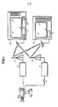
- Figure 5 shows, in block diagram form, an embodiment for converting a high resolution television signal into two transmission signals.
- the active video portion of the high resolution signal is applied to an analog-to-digital converter (ADC) 10.
- ADC analog-to-digital converter
- the digital output from ADC 10 is then applied to a lowpass filter 12 having a cut-off frequency of 7.0 MHz, the output therefrom being applied to a line scan converter 14.
- Line scan converter 14 may be of any suitable type known in the art, for example, the interpolator disclosed in US Patent Re. 31.460, which is hereby incorporated by reference.
- the output from line scan converter 14 is applied to a demultiplexer 16 which is suitably clocked such that the portions of the converted signal constituting the areas A, B1 and B2 shown in Figure 3A appear, respectively, at the three outputs thereof.
- the output corresponding to the area A is then applied to a 5 : 3 time expander 18, which may be a buffer memory and which lengthens each of the lines in area A to the standard 52.5 ⁇ s and also reduces the bandwidth to the standard 4.2 MHz, and then is applied to a digital-to-analog converter (DAC) 20 for application to a first television transmitter (not shown) as the first transmission signal.
- DAC digital-to-analog converter
- the output from ADC is also applied to a high pass filter having a cut-off frequency of 7.0 MHz, and then to a spatio-temporal converter 24, which selects portions of the high spatial frequency information applied thereto for multiplexing into the second transmission signal.
- a spatio-temporal converter 24 is applied to a multiplexer 26.
- Multiplexer 26 also receives every fifth line in the digitized high resolution television signal, identified as line b in the line scan converter 14. Each line b, which has a duration of approximately 42 ⁇ s, is then cut in half in formatter 28 and each half is subjected to a 5 : 3 time expansion in the time expander 30. In the time expander 18, the bandwidth of each half of line b is reduced to 4.2 MHz while the time duration is increased to approximately 35 ⁇ s. This signal is then applied to multiplexer 26. Multiplexer 26 may then be clocked at the standard line frequency f h' and the output signal therefrom applied to multiplexer 32.
- Multiplexer 32 also receives the low spatial frequency information corresponding to areas B1 and B2 from demultiplexer 16 after these signals have been subjected to a 5 : 3 time expansion in time expanders 34 and 36, respectively.
- the resulting time duration of each line in each of the signals B1 and B2 is now approximately 8.7 ⁇ s and has a bandwidth of 4.2 MHz.
- Multiplexer 32 thus forms each line of the second transmission signal by combining a line from B1, a line section from either time expander 30 or spatio-temporal converter 24, and a line from B2, resulting in lines having a duration of approximately 52.5 ⁇ s, which corresponds with the NTSC standard. This signal is then applied to digital-to-analog converter (DAC) 38 for application to a second television transmitter as the second transmission signal.
- DAC digital-to-analog converter
- the spatio-temporal converter 25 may be arranged.
- the signal from highpass filter 22 is divided into half-line segments in formatter 40. These segments are the frequency converted in converter 42 to lie within the bandwidth 0-7.0 MHz.
- This down converted signal comprising half-line segments, is then subjected to a 5 : 3 time expansion in time expander 44, making each half-line segment approximately 35 ⁇ s in duration with a bandwidth of 4.2 MHz.
- the output of time expander 44 is then applied to a five-output demultiplexer 46 clocked at 2-1/2 times the standard line frequency f h .
- the purpose of demultiplexer 46 is to select one out of every five half-line segments applied thereto. Therefore, any of the outputs of demultiplexer 46 constitutes the output of the spatio-temporal converter 24, which is then coupled to multiplexer 26.
- Figure 6B shows a second embodiment of the spatio-temporal converter 24.
- the signal from highpass filter 22 is divided into half-line segments in formatter 40.
- the output from formatter 40 is applied in parallel to bandpass filters 48 and 50 which have the passbands 7.0-10.5 MHz and 10.5-14.0 MHz, respectively.
- the outputs of these filters 48 and 50 are frequency converted to the frequency range 0-3.5 MHz in the frequency converters 52 and 54, respectively, and then subjected to a 5 : 3 time expansion in time expanders 56 and 58, respectively.
- the half-line segments at the respective outputs of time expanders 56 and 58 are 35 ⁇ s in duration and occupy the frequency band 0-2.1 MHz.
- demultiplexers 60 and 62 respectively, which each have five outputs and are clocked at the rate 2-1/2 times f h .
- the signal on one of the outputs from demultiplexer 62 is frequency converted to the band 2.1-4.2 MHz in frequency converter 64 and the converted signal is combined in adder 66 to the signal on one of the outputs from demultiplexer 60.
- the output of the adder 66 forms the output signal from the spatio-temporal converter
- Figure 6C shows another embodiment of the spatio-temporal converter 24.
- the signal from high-pass filter 22 is applied to a programmable bandpass filter and frequency converter 70.
- the programmable filter/converter 70 divides the signal applied thereto into selected frequency bands and then frequency converts these selected bands to a single frequency band.
- the high spatial information occupying the frequency band 7.0-14.0 MHz is divided into five selected frequency bands, for example, 7.0-8.4 MHz, 8.4-9.8 MHz, 9.8-11.2 MHz, 11.2-12.6 MHz and 12.6-14.0 MHz.
- Each of these frequency bands, when selected, is frequency converted to the frequency band 0-1.4 MHz.
- the programmable filter/converter 70 cycles through the selected frequency bands at the standard picture frame rate 1/2 f v .
- US-A 4.004.236 discloses a programmable bandpass filter which may be used in the programmable filter/converter 70 herein and is hereby incorporated by reference.
- the frequency converter portion may be of any suitable design.
- the output from the programmable filter/converter 70 is then subjected to a 3 : 1 time compression in time compressor 72 which reduces the duration of each line to 14 ⁇ s and increases the bandwidth to 4.2 MHz.
- a first formatter 74 is used to divide each of the compressed lines in half.
- a second formatter 76 then combines every five of the input half-lines into a new line, which results in a signal having 262 lines/frame, with a line duration of 35 ⁇ s and a bandwidth of 4.2 MHz.
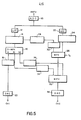
- Figure 7 shows, in block diagram form, an embodiment for reconstructing the high resolution television signal from the two transmission signals.
- the active video portions of the first and the second transmission signals are applied to respective analog-to-digital converters (ADC) 80 and 82.
- ADC analog-to-digital converter
- the output of ADC 82 is then applied to a demultiplexer 84 which provides at two of its three outputs, signals representative of areas B1 and B2.
- These two signals, along with the output signal from ADC 80 representing area A are applied to a multiplexer 86 for forming a low resolution television signal having 525 lines/frame and an aspect ratio of 16 : 9.
- the third output of demultiplexer 84 containing the lines b and the multiplexed high frequency information, is applied to a demultiplexer 88 having two outputs.
- demultiplexer 88 containing the lines b is applied to a 5 : 3 time compressor 90 and a formatter 92, which combines every two half-line segments in the signal b into a single line.
- the output of multiplexer 86 is also applied to a 5 : 3 time compressor 94 and, along with the output of formatter 92, is applied to a line scan converter 96 which is the complement to line scan converter 14.
- Spatio-temporal converter 98 is the complement to the spatio-temporal converter 24 and converts the multiplexed high frequency information back into its original format for combination with the low frequency information.
- the output signal from the line scan converter 96 and the output signal from the spatio-temporal converter 98 are applied to a frame store 100 which combines the two signals and provides a high resolution television signal at the output thereof.
- this signal is then applied to an interlace-to-sequential scan converter 102 which generates additional lines between the lines of the signal applied thereto, thereby, in effect, converting the two-field interlaced 657-line signal having a picture frame rate of 30 hertz, into sequentially-scanned 60-hertz picture frames each having substantially 657 lines.
- Scan converter 102 may be of any suitable design, for example, that disclosed in US-A-4.468.693 of Fujita et al, which is hereby incorporated by reference.
Claims (9)
- Verfahren zum Übertragen eines Hochauflösungsfernsehsignals, das Bilder liefert mit einer Breite, die größer ist als die eines Normbildformats und mit einer Bandbreite, die größer ist als die eines Normfernsehsignals, wobei dieses Hochauflösungsfernsehsignal ein Vielfaches von m Abtastzeilen aufweist, wobei m eine genormte Anzahl Abtastzeilen ist, wobei dieses Verfahren beeinhaltet das Umwandeln des genannten Hochauflösungsfernsehsignal in ein erstes und zweites Übertragungssignal, wobei wenigstens das erste Übertragungssignal zu einem genormten Fernsehempfänger kompatibel ist; wobei die genannte Umwandlung die nachfolgenden Verfahrensschritte aufweist:- das Verteilen des genannten Hochauflösungsfernsehsignals in einen Niederfrequenzteil und einen Hochfrequenzteil;- das Umwandeln des genannten Vielfachen von m Abtastzeilen in dem genannten Niederfrequenzteil in m Zeilen und das Selektieren vorbestimmter Zeilen des genannten Vielfachen von m Abtastzeilen in dem genannten Niederfrequenzteil;- das Selektieren von Information aus den genannten m Zeilen in bezug auf einen selektierten Teil des genannten Hochauflösungsfernsehbildsignals entsprechend dem genannten Bildsignal mit dem genormten Bildformat;- das Übertragen der selektierten Information als das erste Übertragungssignal;- das raumzeitliche Umwandeln des genannten Hochfrequenzteils dadurch, daß der genannte Hochfrequenzteil in eine Anzahl Komponenten aufgeteilt wird und diese Komponenten über die Dauer verschiedener Bilder multiplext werden;- das Kombinieren des umgewandelten Hochfrequenzteils mit den selektierten vorbestimmten Zeilen in dem genannten Niederfrequenzteil und mit der Information aus den genannten m Zeilen, die sich nicht auf den genannten selektierten Teil beziehen;
und- das Übertragen des genannten kombinierten Signals als das zweite Übertragungssignal. - Verfahren zum Übertragen eines Hochauflösungsfernsehsignals nach Anspruch 1, wobei die genannte Raum-Zeit-Umwandlung weiterhin Frequenzherabsetzung und Bandbreitenbegrenzung des genannten Hochfrequenzteils des genannten Hochauflösungsfernsehsignals beinhaltet, derart, daß es innerhalb der Bandbreite des genannten Normfernsehsignals liegt.
- Verfahren zum Übertragen eines Hochauflösungsfernsehsignals nach Anspruch 2, wobei in der genannten raumzeitlichen Umwandlung der genannte Hochfrequenzteil durch Frequenzteilung in p Teile aufgeteilt wird, wobei p eine ganze Zahl ist, wobei diese Teile in dem genannten zweiten Übertragungssignal multiplext werden, wodurch jeder der genannten Teile in einem durch das genannte zweite Übertragungssignal gebildeten, betreffenden Bild enthalten ist.
- Verfahren zum Übertragen eines Hochauflösungsfernsehsignals nach Anspruch 1, wobei die genannten Bilder des genannten Hochauflösungsfernsehens ein Bildformat gleich 16 : 9 haben.
- Fernsehsender zum Übertragen eines Hochauflösungsfern- sehsignals, das Bilder erzeugt mit einer Breite, die größer ist als die eines genormten Bildformats und mit einer Bandbreite, die größer ist als die eines genormten Fernsehsignals, wobei dieses Hochauflösungsfernsehsignal ein Vielfaches von m Abtastzeilen aufweist, wobei m eine genormte Anzahl Abtastzeilen ist, wobei dieser Sender die folgenden Mittel aufweist:- Mittel zum Erzeugen des genannten Hochauflösungsfernsehsignals;- Mittel zum Umwandeln des genannten Hochauflösungsfernsehsignals in ein erstes und zweites Übertragungssignal, wobei wenigstens das genannte erste Übertragungssignal mit einem genormten Fernsehempfänger kompatibel ist, wobei diese Mittel zur Umwandlung Mittel (12, 22) aufweisen zum Verteilen des genannten Hochauflösungsfernsehsignals in einen Niederfrequenzteil und einen Hochfrequenzteil;- Mittel (14) zum Umwandeln des genannten Vielfachen von m Abtastzeilen in dem genannten Niederfrequenzteil in m Zeilen, sowie zum Selektieren vorbestimmter Zeilen des genannten Vielfachen von m Abtastzeilen in dem genannten Niederfrequenzteil;- Mittel (16) zum Selektieren von Information aus den genannten m Zeilen in bezug auf einen selektierten Teil der genannten Hochauflösungsfernsehsignalbilder entsprechend dem genannten genormten Bildformat, wobei diese Information das genannte erste Übertragungssignal bildet;- Mittel (26) zur raumzeitlichen Umwandlung des genannten Hochfrequenzteils, wobei diese Umwandlungsmittel Mittel aufweisen zum Verteilen des genannten Hochfrequenzteils in eine Anzahl Komponenten über die Dauer einiger Bilder;- Mittel (32) zum Kombinieren des genannten umgewandelten Hochfrequenzteils mit den selektierten vorbestimmten Zeilen in dem genannten Niederfrequenzteil, sowie mit der Information aus den genannten m Zeilen, die sich nicht auf den genannten selektierten Teil beziehen;
und- Mittel zur gleichzeitigen Übertragung des genannten ersten und zweiten Übertragungssignals über zwei einzelne Fernsehkanäle. - Fernsehsender nach Anspruch 5, wobei die genannten Mittel (14) zum Umwandeln des genannten Vielfachen von m Abtastzeilen einen Zeilenabtastwandler (14) aufweisen, der vier Ausgangszeilen a, f, g, h aus jeweils fünf Eingangszeilen a, b, c, d, e erzeugt und zwar unter Anwendung der Beziehung a=a, f=(3b+c)/4, g=(c+d)/2 und h=(d+3e)/4.
- Fernsehsender nach Anspruch 6, wobei die selektierten vorbestimmten Zeilen in dem genannten Niederfrequenzteil die Zeilen b sind.
- Fernsehempfänger zum Empfangen eines übertragenen Hochauflösungsfernsehsignals, das Bilder liefert mit einer Breite, die größer ist als die eines genormten Bildformats und mit einer Bandbreite, die größer ist als die eines genormten Fernsehsignals, wobei das genannte Hochauflösungsfernsehsignal ein Vielfaches von m Abtastzeilen aufweist, wobei m eine genormte Anzahl Abtastzeilen ist, wobei dieser Fernsehempfänger die nachfolgenden Elemente aufweist:- Mittel zum gleichzeitigen Empfangen eines ersten und eines zweiten Übertragungssignals;- Mittel zum Umwandeln des genannten ersten und zweiten Übertragungssignals in ein rekonstruiertes Hochauflösungsfernsehsignal, wobei diese Umwandlungsmittel die nachfolgenden Elemente aufweisen:- Mittel (84) zum Abtrennen von Information von m Zeilen, die nicht zu einem selektierten Teil gehören entsprechend einem genormten Bildformat von dem genannten zweiten Übertragungssignal;- Mittel (86) zum Kombinieren der genannten abgetrennten Information mit dem genannten empfangenen ersten Übertragungssignal zum Bilden eines breiten Fernsehsignals;- Mittel (88) zum Abtrennen der selektierten vorbestimmten Zeilen des genannten Vielfachen von m Abtastzeilen in einem Niederfrequenzteil des genannten übertragenen Hochauflösungsfernsehsignals von dem genannten zweiten Übertragungssignal;- Mittel (96) zum Kombinieren der genannten abgetrennten vorbestimmten Zeilen mit dem genannten breiten Fernsehsignal zum Bilden eines Niederfrequenzteils des genannten rekonstruierten Hochauflösungsfernsehsignals;- Mittel (98) zur raumzeitlichen Bildung eines Hochfrequenzteils des genannten rekonstruierten Hochauflösungsfernsehsignals aus dem genannten umgewandelten Hochfrequenzteil in dem genannten zweiten Übertragungssignal;
und- Mittel (100) zum Addieren des genannten gebildeten Niederfrequenzteils und des genannten gebildeten Hochfrequenzteils zum Bilden des rekonstruierten Hochauflösungsfernsehsignals. - Fernsehempfänger nach Anspruch 8, wobei dieser Fernsehempfänger weiterhin einen mit den genannten Addiermitteln (100) gekoppelten Zeilensprungverfahren-zu-Sequentiellverfahren-Wandler (102) aufweist zum Erzeugen zwischenliegender Zeilen zwischen den Zeilen in jedem Teilbild des genannten rekonstruierten Hochauflösungsfernsehsignals, wobei auf effektive Weise ein sequentiell abgetastetes Bild mit einer Bildfrequenz erzeugt wird, die der doppelten Bildfrequenz des genannten genormten Fernsehbildes entspricht.
Applications Claiming Priority (2)
| Application Number | Priority Date | Filing Date | Title |
|---|---|---|---|
| US06/684,546 US4670783A (en) | 1984-12-21 | 1984-12-21 | High resolution television system |
| US684546 | 1984-12-21 |
Publications (3)
| Publication Number | Publication Date |
|---|---|
| EP0187406A2 EP0187406A2 (de) | 1986-07-16 |
| EP0187406A3 EP0187406A3 (en) | 1987-05-27 |
| EP0187406B1 true EP0187406B1 (de) | 1991-02-27 |
Family
ID=24748501
Family Applications (1)
| Application Number | Title | Priority Date | Filing Date |
|---|---|---|---|
| EP85201954A Expired - Lifetime EP0187406B1 (de) | 1984-12-21 | 1985-11-26 | Hochauflösungsfernsehsendesystem |
Country Status (5)
| Country | Link |
|---|---|
| US (1) | US4670783A (de) |
| EP (1) | EP0187406B1 (de) |
| JP (1) | JPS61154387A (de) |
| CA (1) | CA1243111A (de) |
| DE (1) | DE3581916D1 (de) |
Families Citing this family (19)
| Publication number | Priority date | Publication date | Assignee | Title |
|---|---|---|---|---|
| US4772949A (en) * | 1984-12-21 | 1988-09-20 | North American Philips Corp. | High resolution television transmission system |
| FR2604843A1 (fr) * | 1986-10-07 | 1988-04-08 | Thomson Csf | Dispositif de reception d'emissions de radio, de television ou d'echos radar |
| FR2604842B1 (fr) * | 1986-10-07 | 1989-02-24 | Thomson Csf | Dispositif et procede de transmission ou de stockage d'informations optimisant l'utilisation de la bande passante |
| US5005126A (en) * | 1987-04-09 | 1991-04-02 | Prevail, Inc. | System and method for remote presentation of diagnostic image information |
| AU608650B2 (en) * | 1987-07-27 | 1991-04-11 | General Electric Company | Compatible widescreen television system |
| US4816899A (en) * | 1987-07-27 | 1989-03-28 | General Electric Company | Compatible widescreen television system |
| US4853766A (en) * | 1987-07-27 | 1989-08-01 | General Electric Company | Widescreen video signal processor with auxiliary modulated by widescreen information |
| AU611481B2 (en) * | 1987-07-27 | 1991-06-13 | General Electric Company | Video signal processor with alternate subcarrier |
| EP0377668B2 (de) * | 1987-09-14 | 1997-07-09 | General Electric Company | Kompatibles fernsehsystem mit kompandierung von hilfsignal kodierter information |
| IT1215909B (it) * | 1988-02-18 | 1990-02-22 | Rai Radiotelevisione Italiana | Procedimento di generazione e trasmissione di segnali televisivi a colori ad alta definizione compatibile con gli standardattuali e procedimento e apparecchiatura di ricezione didetti segnali. |
| US4977454A (en) * | 1988-08-31 | 1990-12-11 | U.S. Philips Corporation | HDNTSC channel with frequency multiplexing |
| JP2533393B2 (ja) * | 1990-02-16 | 1996-09-11 | シャープ株式会社 | Ntsc―hdコンバ―タ |
| JP2861213B2 (ja) * | 1990-03-13 | 1999-02-24 | ソニー株式会社 | 画像表示装置 |
| JPH07121108B2 (ja) * | 1990-03-24 | 1995-12-20 | 日本テレビ放送網株式会社 | テレビジョン方式 |
| KR0155688B1 (ko) * | 1991-09-28 | 1998-11-16 | 강진구 | 텔레비젼신호 변환장치 |
| US5461427A (en) * | 1994-06-28 | 1995-10-24 | Thomson Consumer Electronics, Inc. | Television receiver having the capability to associate any HDTV and any NTSC channel |
| US5453796A (en) * | 1994-06-28 | 1995-09-26 | Thomson Consumer Electronics, Inc. | Signal swap apparatus for a television receiver having an HDTV main picture signal processor and an NTSC Pix-in-Pix signal processor |
| JP5903835B2 (ja) * | 2011-04-28 | 2016-04-13 | 株式会社リコー | 伝送端末、画像表示制御方法、画像表示制御プログラム、記録媒体、および伝送システム |
| CN103347216A (zh) * | 2013-06-29 | 2013-10-09 | 苏州市牛勿耳关电器科技有限公司 | 一种智能led电视机 |
Family Cites Families (6)
| Publication number | Priority date | Publication date | Assignee | Title |
|---|---|---|---|---|
| NL8104476A (nl) * | 1981-10-01 | 1983-05-02 | Philips Nv | Televisiesysteem voor hoge-definitie televisie en er voor geschikte televisie zender en ontvanger. |
| GB2132443A (en) * | 1982-12-22 | 1984-07-04 | Philips Electronic Associated | Television transmission system |
| GB2132444A (en) * | 1982-12-22 | 1984-07-04 | Phillips Electronic And Associ | Television transmission system |
| GB2139448B (en) * | 1983-03-02 | 1986-05-21 | British Broadcasting Corp | High definition video signal transmission |
| GB2138238B (en) * | 1983-03-02 | 1987-07-08 | British Broadcasting Corp | High definition video signal transmission |
| US4564857A (en) * | 1984-02-28 | 1986-01-14 | At&T Bell Laboratories | Aspect ratio improvement for compatible high-definition television |
-
1984
- 1984-12-21 US US06/684,546 patent/US4670783A/en not_active Expired - Fee Related
-
1985
- 1985-11-26 DE DE8585201954T patent/DE3581916D1/de not_active Expired - Lifetime
- 1985-11-26 EP EP85201954A patent/EP0187406B1/de not_active Expired - Lifetime
- 1985-12-18 JP JP60283175A patent/JPS61154387A/ja active Pending
- 1985-12-20 CA CA000498364A patent/CA1243111A/en not_active Expired
Also Published As
| Publication number | Publication date |
|---|---|
| US4670783A (en) | 1987-06-02 |
| EP0187406A3 (en) | 1987-05-27 |
| DE3581916D1 (de) | 1991-04-04 |
| CA1243111A (en) | 1988-10-11 |
| EP0187406A2 (de) | 1986-07-16 |
| JPS61154387A (ja) | 1986-07-14 |
Similar Documents
| Publication | Publication Date | Title |
|---|---|---|
| EP0187406B1 (de) | Hochauflösungsfernsehsendesystem | |
| EP0018856B1 (de) | Fernseh-Wiedergabesystem | |
| EP0146713B2 (de) | Multiplex Sub-Nyquist-Abtastungübertragungssystem für ein hochauflösendes Farbfernsehbildsignal | |
| US4794447A (en) | Method and apparatus for transmitting and receiving a high definition NTSC compatible television signal over a single DBS channel in time division multiplex form | |
| US5231491A (en) | Television system providing wide aspect ratio image information compatible with a standard aspect ratio format | |
| US4605952A (en) | Compatible HDTV system employing nonlinear edge compression/expansion for aspect ratio control | |
| US5187575A (en) | Source adaptive television system | |
| US4979041A (en) | High definition television system | |
| US4908697A (en) | Two-line mac high definition television system | |
| WO1986006914A1 (en) | System for transferring three-dimensional tv images | |
| US4967272A (en) | Bandwidth reduction and multiplexing of multiple component TV signals | |
| US4621287A (en) | Time-multiplexing of an interleaved spectrum of a television signal | |
| US4613903A (en) | High-resolution television transmission system | |
| KR20000057398A (ko) | 디지탈 방송 시스템 | |
| KR920009072B1 (ko) | 고화질 텔레비젼 및 이들 신호의 송수신 방법 | |
| US4974064A (en) | Apparatus for encoding television signals of different formats for transmission and decoding upon reception | |
| US4772949A (en) | High resolution television transmission system | |
| JPH0247918B2 (de) | ||
| US5029002A (en) | High definition television system | |
| US4523220A (en) | Compatible high-definition television system utilizing Hadamard basis functions | |
| US5113242A (en) | Two-line MAC high definition television system | |
| KR0142586B1 (ko) | 종래의 텔레비젼 시스템과 호환가능한 텔레비젼 전송 시스템 | |
| GB2191062A (en) | Transmitting television signals | |
| EP0598786B1 (de) | Verfahren, coder und decoder zur kompatiblen übertragung und/oder aufzeichnung von progressiven bildsignalen | |
| JP2594596B2 (ja) | 画像信号伝送方式 |
Legal Events
| Date | Code | Title | Description |
|---|---|---|---|
| PUAI | Public reference made under article 153(3) epc to a published international application that has entered the european phase |
Free format text: ORIGINAL CODE: 0009012 |
|
| AK | Designated contracting states |
Kind code of ref document: A2 Designated state(s): DE FR GB |
|
| PUAL | Search report despatched |
Free format text: ORIGINAL CODE: 0009013 |
|
| AK | Designated contracting states |
Kind code of ref document: A3 Designated state(s): DE FR GB |
|
| 17P | Request for examination filed |
Effective date: 19871103 |
|
| 17Q | First examination report despatched |
Effective date: 19891023 |
|
| GRAA | (expected) grant |
Free format text: ORIGINAL CODE: 0009210 |
|
| AK | Designated contracting states |
Kind code of ref document: B1 Designated state(s): DE FR GB |
|
| REF | Corresponds to: |
Ref document number: 3581916 Country of ref document: DE Date of ref document: 19910404 |
|
| ET | Fr: translation filed | ||
| PG25 | Lapsed in a contracting state [announced via postgrant information from national office to epo] |
Ref country code: GB Effective date: 19911126 |
|
| PLBE | No opposition filed within time limit |
Free format text: ORIGINAL CODE: 0009261 |
|
| STAA | Information on the status of an ep patent application or granted ep patent |
Free format text: STATUS: NO OPPOSITION FILED WITHIN TIME LIMIT |
|
| 26N | No opposition filed | ||
| GBPC | Gb: european patent ceased through non-payment of renewal fee | ||
| PG25 | Lapsed in a contracting state [announced via postgrant information from national office to epo] |
Ref country code: FR Effective date: 19920731 |
|
| PG25 | Lapsed in a contracting state [announced via postgrant information from national office to epo] |
Ref country code: DE Effective date: 19920801 |
|
| REG | Reference to a national code |
Ref country code: FR Ref legal event code: ST |