EP0187389B1 - Apparatus for obtaining image information through use of a nuclear magnetic resonance signal - Google Patents
Apparatus for obtaining image information through use of a nuclear magnetic resonance signal Download PDFInfo
- Publication number
- EP0187389B1 EP0187389B1 EP85116651A EP85116651A EP0187389B1 EP 0187389 B1 EP0187389 B1 EP 0187389B1 EP 85116651 A EP85116651 A EP 85116651A EP 85116651 A EP85116651 A EP 85116651A EP 0187389 B1 EP0187389 B1 EP 0187389B1
- Authority
- EP
- European Patent Office
- Prior art keywords
- magnetic field
- coil
- magnet
- ring
- static
- Prior art date
- Legal status (The legal status is an assumption and is not a legal conclusion. Google has not performed a legal analysis and makes no representation as to the accuracy of the status listed.)
- Expired
Links
Images


Classifications
-
- G—PHYSICS
- G01—MEASURING; TESTING
- G01R—MEASURING ELECTRIC VARIABLES; MEASURING MAGNETIC VARIABLES
- G01R33/00—Arrangements or instruments for measuring magnetic variables
- G01R33/20—Arrangements or instruments for measuring magnetic variables involving magnetic resonance
- G01R33/28—Details of apparatus provided for in groups G01R33/44 - G01R33/64
- G01R33/32—Excitation or detection systems, e.g. using radio frequency signals
- G01R33/34—Constructional details, e.g. resonators, specially adapted to MR
- G01R33/341—Constructional details, e.g. resonators, specially adapted to MR comprising surface coils
-
- G—PHYSICS
- G01—MEASURING; TESTING
- G01R—MEASURING ELECTRIC VARIABLES; MEASURING MAGNETIC VARIABLES
- G01R33/00—Arrangements or instruments for measuring magnetic variables
- G01R33/20—Arrangements or instruments for measuring magnetic variables involving magnetic resonance
- G01R33/28—Details of apparatus provided for in groups G01R33/44 - G01R33/64
- G01R33/38—Systems for generation, homogenisation or stabilisation of the main or gradient magnetic field
- G01R33/383—Systems for generation, homogenisation or stabilisation of the main or gradient magnetic field using permanent magnets
-
- G—PHYSICS
- G01—MEASURING; TESTING
- G01R—MEASURING ELECTRIC VARIABLES; MEASURING MAGNETIC VARIABLES
- G01R33/00—Arrangements or instruments for measuring magnetic variables
- G01R33/20—Arrangements or instruments for measuring magnetic variables involving magnetic resonance
- G01R33/28—Details of apparatus provided for in groups G01R33/44 - G01R33/64
- G01R33/38—Systems for generation, homogenisation or stabilisation of the main or gradient magnetic field
- G01R33/387—Compensation of inhomogeneities
- G01R33/3873—Compensation of inhomogeneities using ferromagnetic bodies ; Passive shimming
Definitions
- the present invention relates to an apparatus for obtaining image information from a living body under examination through use of a nuclear magnetic resonance signal, and more particularly to the relative arrangement of its static magnetic field and radio-frequency magnetic field and the examinee's body.
- NMR-CT apparatus nuclear magnetic resonance-CT apparatus
- the NMR phenomenon occurs through such a mechanism as follows:
- atomic nuclei When placed in a static magnetic field, atomic nuclei resonate with a component of a radio-frequency magnetic field (hereinafter referred to as RF magnetic field or simply as RF field) of a specified frequency proportional to the intensity of the static magnetic field (which may hereinafter be referred to as static field which is perpendicular to that component, and precess about an axis in the direction of application of the static magnetic field at the above frequency (a resonance frequency).
- static field which is perpendicular to that component
- a resonance frequency By the precession the atomic nuclei absorb the energy of the RF magnetic field and are excited and upon completion of the excitation, they relax while releasing, as an NMR signal, a portion of the absorbed energy of the RF field.
- a magnetic field which has the same direction as the static magnetic field and whose intensity varies along a specified direction that is, a so-called gradient magnetic field (which may hereinafter be referred to as gradient field)
- gradient field which may hereinafter be referred to as gradient field
- nuclear spins atomic nuclei
- Fig. 1 illustrates in block form specific constituents of the NMR-CT apparatus.
- a static magnetic field generating magnet 11 applies a static magnetic field to a living body (not shown) and a gradient magnetic field generating coil 12 applies thereto a gradient magnetic field.
- the gradient field is identical in direction with the static field and its intensity is graded in three directions which usually intersect one another at right angles. This field arrangement permits discrimination of spatial information of the body.
- RF power in the resonance frequency band is provided from a transmitter 13 via an automatic transmission/ reception switching circuit 14 to an RF coil 15.
- An RF magnetic field which is perpendicular to the static field, is applied from the RF coil 15 to the body.
- the resulting NMR signal from the body is received by the RF coil 15, from which it is supplied to a receiver 17 via the automatic transmission/reception switching circuit 14 and a receiving coil select circuit 15.
- the NMR signal is converted by an A/D converter 18 into a digital signal.
- the digital signal is provided to a computer 19, in which it is subjected to a calculation process for image reconstruction, etc., and its results are displayed as an image on a display 20.
- the static field generating magnet 11 is excited by a static field generating means 11 a and the gradient field generating coil 12 by a gradient field generating means 12a.
- the static field direction When the direction of the magnetic fields emanating from the static field generating magnet 11 and the gradient field generating coil 12 (which direction will hereinafter be referred to as the static field direction) perpendicularly intersect the direction of the RF magnetic field (hereinafter referred to as the RF direction) from the RF coil 15, the application of the RF field and the detection of the NMR signal can be achieved with the highest efficiency.
- the NMR-CT apparatus satisfying above conditions are roughly divided into two groups in terms of the magnetic field generating structure. In a group 1 the static field direction and the direction in which a human body is taken into and out of the static field are perpendicularto each other, whereas in a group 2 the both directions are parallel to each other.
- a solenoid coil is often used as the RF coil in the case of the group 1, and in the case of the group 2 a saddle-shaped coil is usually employed.
- the RF coil for detecting the NMR signal is natually one of important components which determine the SN ratio of the NMR-CT.
- the solenoid coil is about three times higher than the saddle-shaped coil in RF sensitivity.
- an RF coil commonly referred to as a surface coil is often used according to the region of examination (limited to regions near the skin surface).
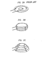
- the surface coil has a spiral configuration, as shown in Fig. 2A, which is substantially flat and small in the number of turns.
- the RF field emanating from the surface coil is perpendicular to the coil plane.
- the surface coil is designed so that the SN ratio of the NMR signal from the region of examination may be maximum taking into account an area of the region of examination. In practical use the surface coil is applied to the skin surface corresponding to the region of examination with the coil plane held in parallel to the skin surface.
- a surface coil 21 is connected to the receiver 17 via the receiving coil select circuit 16 which switches between the surface coil 21 and the solenoid coil 15.as required. That is, the RF field is applied to the body from the solenoid coil 15 and the NMR signal from the body is received by the solenoid coil 15 and the surface coil 21, and selectively provided via the receiving coil select circuit 16 to the receiver 17.
- the receiving coil select circuit 16 selectively connects the automatic transmission/reception switching circuit 14 and the surface coil 21 to the receiver 17. It is possible to arrange such that the solenoid coil 15 and the surface coil 21 are selectively connected to the automatictransmission/reception switching circuit 14, the receiver 17 is connected directly to the automatic transmission/reception switching circuit 14. In this case, if desired, the surface coil 21 may be used both for generation of the RF field and reception of NMR signal.
- the static field direction must be made horizontal so as to meet the aforementioned requirement that the static field direction and the RF direction be perpendicular to each other.
- the static field direction is parallel to the longitudinal axis of the lying human body, and hence is originally horizontal, but in the magnet system of the group 1 the static field direction is conventionally limited specifically to the direction perpendicular to the lying human body.
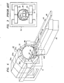
- the static field generating means employing permanent magnets is such as shown in Fig. 3 in which different magnetic poles of the permanent magnets 22 and 23 are disposed opposite but spaced apart in the vertical direction and are interconnected via a magnetic yoke 24, setting up a vertical static field 25 between the opposing faces of the magnets 22 and 23.
- a solenoid coil 26 forthe RF magnetic field is disposed in the static magnetic field 25.
- the axis of the solenoid coil 26 is extended in a horizontal direction and is perpendicularto the static field 25.
- a deck 27 is horizontally disposed in a mannerto be slidable in parallel with the axis of the solenoid coil 26 and an examinee 28 lies on the deck 27.
- the magnet system of the group 1 presents the probem that the surface coil cannot be used with its RF direction held vertical.
- WO-A-84/01226 discloses an apparatus according to the preamble of claim 1. There are provided a plurality of ring magnets each comprising a plurality of segments and the magnetization directions of the respective segments are selected to form a uniform static magnetic field inside the ring magnets which is directed vertically.
- An object of the present invention is to provide an NMR-CT apparatus which has the magnet system of the group 1 capable of using the solenoid coil about three times higher in the RF sensitivity than the saddle-shaped coil and which allows to use the surface coil of the vertical RF direction which is effective for examination of the internal organs or regions near the skin surface.
- High-frequency pulses are applied to the solenoid coil or surface coil and an NMR signal is received by either one of the solenoid coil or surface coil and is supplied to the receiver, and then processed to obtain spatial distribution information, which is displayed as an image.
- the NMR signals from both the solenoid coil and surface coil may be supplied to the receiver.
- Means for generating the static magnetic field may preferably be formed by a plurality of magnet rings each of which comprises a plurality of permanent magnet blocks disposed in the form of a ring so that they provide magnetic fields of substantially one direction within the magnet ring.
- the magnet rings are arranged side by side with their axes held in agreement with one another to extend in the horizontal direction. It is preferableto provide means for adjusting the position of each magnet block in the radial direction of each magnet ring, in the skew direction aboutthat radial direction and in the tangential direction.
- FIGs. 4 to 7 illustrate an embodiment of the present invention.
- a static magnetic field generating device 32 is mounted on a mount 31.
- the static field is generated by a permanent magnet assembly through use of a technique disclosed in United States Patent No. 4,498,048.
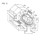
- three magnet rings 34a, 34b and 34c each composed of eight anisotropic permanent magnet blocks 33 arranged in the form of a ring, are coaxially aligned in the horizontal direction.
- the magnet blocks of each magnet ring are respectively magnetized in such directions as indicated by the arrows 35, developing a horizontal static magnetic field 36 inside the magnet ring.
- the magnet rings 34a, 34b and 34c are respectively secured to magnet support frame means 37a, 37b and 37c outside thereof and the magnet support frame means are fixedly mounted on the mount 31, as shown in Fig. 4.
- a bobbin 38 is disposed inside the magnet rings 34a, 34b and 34c coaxially therewith and a gradient field coil 39 is wound on the bobbin 38. Both ends of the bobbin 38 project outwardly of the magnet rings 34a and 34c and are held on support bases 41 a and 41 b.
- the gradient field coil 39 is comprised of a coil 39z for generating a Z-direction gradient field the intensity of which varies in a direction parallel to the axis of the bobbin 38, a coil 39y for generating a Y-direction gradient field the intensity of which varies in the Y-direction and a coil 39x for generating an X-direction field the intensity of which varies in the X-direction.
- the coil 39z is wound, for instance, in such a form as shown in Fig. 8A and its particulars are disclosed, for example, in Japanese Patent Application Laid Open No. 15749/84.
- the coils 39y and 39x are wound on the coil 39z, for example, in such forms as shown in Figs. 8b and 8C, respectively. Their winding configurations are described in detail in Japanese Patent Application Laid Open No. 57140/80. These gradient field are all produced in the Z-direction.
- a rail 42 is fixedly mounted on the bottom of the bobbin 38 inside thereof to extend in the Z-direction.
- a slot 42S is cut in the rail 42 to extend from one end to the center thereof in the Z-direction and a solenoid coil 43 is disposed inside the bobbin 38, passing through the slot 42S.
- the solenoid coil 43 is wound on a bobbin 44 with its axis held in parallel to the Z-axis and is positioned corresponding to the magnet ring 34b.
- the bobbin 44 is detachably secured to the rail 42.
- a bed 45 with its top surface almost flash with that of the rail 42.
- a carriage 46 for carrying an examinee 47 is mounted on the bed 45 in a manner to be slidable into and out of the bobbin 38.
- rollers 48 are attached to the rail 42 and the bed 45 as required.
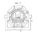
- the examinee 47 is brought into and out of the bobbin 38 in a direction perpendicular to the horizontal static magnetic field 36 as shown in Fig. 7 so that the static field 36 is applied perpendicularly to the longitudinal axis of the examinee's body.
- a recess 51 is made in the carriage 46 for receiving therein a surface coil 49, as required, which allows easy positioning of the examinee's body relative to the surface coil 49 before inserting the body into the bobbin 38.
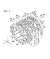
- Fig. 9 shows a practical arrangement of the static field generating device 32, wherein each of the magnet support frame means 37a, 37b, 37c is formed by a pair of parallel ring plates 59 and 61 and each magnet block 33 is mounted to the parallel ring plates via position adjusting means as will be explained hereinafter.
- the magnet blocks are each produced by binding a number of small magnet pieces in combination.
- provision is made for adjusting the position of each magnet ring in its axial direction, the position of each magnet block 33 in the radial and tangential directions of the magnet ring and angular position of rotaton of the magnet block 33 i.e.
- the magnet support frame means 37a, 37b and 37c are loosely threaded with common coupling rods 53 and nuts 54 are threadedly engaged with the coupling rods 53 to clamp each support frame means on both sides thereof, fixing it in position.
- tangential/skew adjusting means 87, 88 are fixedly mounted to each pair of the ring plates on both outer side thereof in a corresponding relation to the respective magnet blocks of each magnet ring.
- the radial adjusting means 75 for each magnet block 33 of the inner magnet ring 34b is formed as a wedge type adjusting mechanism.
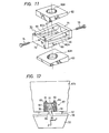
- Figs. 10A, 10Band 11 show an example of the wege type radial adjustment mechanism.
- An engaging ring 57 is mounted on a back plate 56 of the magnet block 33 and a rod 58 is engaged at one end thereof with the engaging ring 57 through its flange 58a so that the rod 58 is rotatably mounted on the magnet block 33.
- the pair of opposed ring plates 59b and 61b are interconnected through a pair of wedge plates 62 and 63 at the position of each magnet block 33.
- the abovementioned rod 58 is received in holes 62H, 63H made in the wedge plates 62 and 63.
- the rod 58 has an engaging flange 64 formed integrally therewith between the wedge plates 62 and 63. As shown in Fig.
- a pair of upper wedge bars 65, 66 are fixedly attached at thicker ends thereof to upper side corners of a coupling plate 71 and a pair of lower wedge bars 67, 68 are similarly fixed to lower side corners of a coupling plate 72.
- the thinner ends of the wedge bars 65, 66 and 67, 68 are connected to the upper and lower ends of the opposite coupling plates 72 and 71, respectively, so as to form a wedge frame 70 having rectangular guide apertures 6Ga and 6Gb defined between the wedge bars 65 and 67 and between the wedge bars 66 and 68.
- the wedge frame 70 is slidably interposed between the upper and lower wedge plates 62 and 63.
- the rod 58 is engaged with the wedge frame 70 to extend through between the wedge bars 65 and 66 and between the wedge bars 66 and 68, with radially opposite parts of the engaging flange 64 being slidably disposed in the guide apertures 6Ga, 6Gb.
- the coupling plates 71 and 72 have made therein threaded holes, in which bolts 73 and 74 are threadedly received with their tips abutted against the peripheral surface of the engaging flange 64. In this way, a radially adjusting wedge mechanism 75 is formed.
- the wedge frame 70 is pulled out in a direction in which the coupling plate 71 moves away from a center axis of the rod 58. Since the wedge plates 62 and 63 are fixed to the ring plates 59b, 61 b, the engaging flange 64 is pushed up to move the rod 58 and the magnet block 33 in a direction opposite from the arrow ⁇ , that is, radially of the magnet ring 34b away from its axis.
- the radially adjusting wedge mechanism permits fine control but is somewhat complex in structure.
- the outer magnet rings 34a and 34c do not call for such fine control as is needed for the magnet ring 34b sandwiched therebetween. That is, adjustment of the magnet ring 34b, even if slight, will exert a great influence. From this viewpoint, only a simple bolt type adjustment mechanism 89 is employed in place of the radial adjusting wedge mechanism 75 for each magnet block in the outer magnet rings 34a, 34c as shown in Fig. 9.
- the bolt type adjustment mechanism 89 has an arrangement in which a threaded rod 92 is screwed into a hole made in a disk 93 mounted on coupling plate 91 joining the pair of ring plates (59a, 61a; 59c, 61 c) and are rotatably connected at one end to the magnet blocks 33. By turning the threaded rods 92, the magnet blocks 33 are moved back and forth radially of the magnet ring.
- the tangential/skew adjusting means 87, 88 is provided in association with each magnet block 33 on outer sides of each pair ring plates 59, 61 as shown in Fig. 9 and will be explained hereinafter with respect to Figs. 10B and 12.
- On the outside of the ring plate 61 opposite from the rod 58 is fixedly mounted a wedge case 76 above the back plate 56 of the magnet block 33, as depicted in Figs. 10B and 12.
- the wedge case 76 is open on the side of the magnet block 33 and has disposed therein an engaging wedge piece 77. In the wedge case 76 wedges 78 and 79 are pressed into between side panels of the case 76 and the engaging wedge piece 77.
- the magnet rings 34a, 34b and 34c were each comprised of eight magnet blocks 33, each of which was produced by binding a number of rare earth iron magnets (measuring 50x30x20 mm) of Nd-Fe-B series whose residual magnetism was in the range of 12.0 to 12.6 K gausses, a homogeneous magnetic field with a difference between maximum and minimum field intensities held within 30 ppm was obtained inside a cylindrical plane with a radius of 175 mm from the center of each magnet ring.
- a homogeneous magnetic field can be obtained in a wide space. In particular, sufficiently high resolution can be obtained even if magnetic fields are applied to the examinee's body horizontally along the longer diameter of the elliptical cross-section of the body.
- the shape of the surface coil can be selected in accordance with the surface configuration of a particular region of examination. For example, in the case of examining the breast, such a spiral surface coil of a cone-shape as shown in Fig. 2C may be used. In any case, since the static magnetic field is horizontal, the surface coil 49 can be disposed with its RF direction held vertically, permitting effective examination of various parts of the examinee's body. Moreover, S/N of the received signal can be further improved by obtaining NMR signals from both the solenoid coil 43 and the surface coil 49 and supplying them to the receiver 17.
- the magnets 101 and 102 are interconnected via a magnetic yoke 103. That is, the opposed magnets 101 and 102 are disposed on the left and right of the examinee's body 47 so that the static field 36 is horizontally directed and is perpendicular to the longitudinal axis of the examinee's body 47.
- the solenoid coil 43 can be employed for the purpose of obtaining a uniform tomographic image of the entire region of the head or the body of the examinee 47.
- Fig. 14 In the case of using resistive magnets, an arrangement such as depicted in Fig. 14 is employed, in which static field coils 104 and 105 are arranged horizontally in opposing relation, so that their axes are horizontal.
- the RF field generating solenoid coil 43 and the carriage 46 are disposed between the static field coils 104 and 105.
- the static field coils 104 and 105 are excited by a power supply 106.
- the gradient field generating coil is also provided, though not shown.
- a solenoid coil of high sensitivity is used and a surface coil can be employed with its RF direction held vertical. Accordingly, it is possible to use an RF coil most suitable for a particular region for examination at all times.
Description
- The present invention relates to an apparatus for obtaining image information from a living body under examination through use of a nuclear magnetic resonance signal, and more particularly to the relative arrangement of its static magnetic field and radio-frequency magnetic field and the examinee's body.
- Many literatures have already been published on apparatus for obtaining image information from a living body particularly, human body through utilization of a nuclear magnetic resonance (hereinafter referred to simply as NMR) signal (which apparatus will hereinafter be referred to as the NMR-CT apparatus).
- To begin with, the NMR phenomenon occurs through such a mechanism as follows: When placed in a static magnetic field, atomic nuclei resonate with a component of a radio-frequency magnetic field (hereinafter referred to as RF magnetic field or simply as RF field) of a specified frequency proportional to the intensity of the static magnetic field (which may hereinafter be referred to as static field which is perpendicular to that component, and precess about an axis in the direction of application of the static magnetic field at the above frequency (a resonance frequency). By the precession the atomic nuclei absorb the energy of the RF magnetic field and are excited and upon completion of the excitation, they relax while releasing, as an NMR signal, a portion of the absorbed energy of the RF field. The resonance frequency is known under the name of a Larmor frequency and is given by ωe=γ. He, where y is a nuclear gyromagnetic ratio and He is the intensity of the static magnetic field.
- Then, when a magnetic field which has the same direction as the static magnetic field and whose intensity varies along a specified direction, that is, a so-called gradient magnetic field (which may hereinafter be referred to as gradient field), is superimposed on the spatially homogeneous static magnetic field, atomic nuclei (hereinafter referred to as nuclear spins) at respective coordinates in the above specified direction precess at different frequencies by virtue of the RF magnetic field.
- It can be said that it is the NMR-CT that obtains, by an ingenious utilization of above-mentioned property, the spatial distribution of information (the nuclear spin density, the relaxation time, etc.) contained in the NMR signal. Fig. 1 illustrates in block form specific constituents of the NMR-CT apparatus. A static magnetic
field generating magnet 11 applies a static magnetic field to a living body (not shown) and a gradient magneticfield generating coil 12 applies thereto a gradient magnetic field. The gradient field is identical in direction with the static field and its intensity is graded in three directions which usually intersect one another at right angles. This field arrangement permits discrimination of spatial information of the body. RF power in the resonance frequency band is provided from atransmitter 13 via an automatic transmission/reception switching circuit 14 to anRF coil 15. An RF magnetic field, which is perpendicular to the static field, is applied from theRF coil 15 to the body. The resulting NMR signal from the body is received by theRF coil 15, from which it is supplied to areceiver 17 via the automatic transmission/reception switching circuit 14 and a receiving coilselect circuit 15. After being amplified and detected in thereceiver 17 the NMR signal is converted by an A/D converter 18 into a digital signal. The digital signal is provided to acomputer 19, in which it is subjected to a calculation process for image reconstruction, etc., and its results are displayed as an image on adisplay 20. The staticfield generating magnet 11 is excited by a static field generating means 11 a and the gradientfield generating coil 12 by a gradient field generating means 12a. - When the direction of the magnetic fields emanating from the static
field generating magnet 11 and the gradient field generating coil 12 (which direction will hereinafter be referred to as the static field direction) perpendicularly intersect the direction of the RF magnetic field (hereinafter referred to as the RF direction) from theRF coil 15, the application of the RF field and the detection of the NMR signal can be achieved with the highest efficiency. The NMR-CT apparatus satisfying above conditions are roughly divided into two groups in terms of the magnetic field generating structure. In a group 1 the static field direction and the direction in which a human body is taken into and out of the static field are perpendicularto each other, whereas in a group 2 the both directions are parallel to each other. - Since it is necessary that the static field direction and the RF direction be perpendicular to each other, as referred to above, a solenoid coil is often used as the RF coil in the case of the group 1, and in the case of the group 2 a saddle-shaped coil is usually employed.
- The RF coil for detecting the NMR signal is natually one of important components which determine the SN ratio of the NMR-CT. The solenoid coil is about three times higher than the saddle-shaped coil in RF sensitivity. Recently there has been a strong demand for higher sensitivity, and an RF coil commonly referred to as a surface coil is often used according to the region of examination (limited to regions near the skin surface). Usually the surface coil has a spiral configuration, as shown in Fig. 2A, which is substantially flat and small in the number of turns. The RF field emanating from the surface coil is perpendicular to the coil plane. The surface coil is designed so that the SN ratio of the NMR signal from the region of examination may be maximum taking into account an area of the region of examination. In practical use the surface coil is applied to the skin surface corresponding to the region of examination with the coil plane held in parallel to the skin surface.
- As depicted in Fig. 1, a
surface coil 21 is connected to thereceiver 17 via the receiving coilselect circuit 16 which switches between thesurface coil 21 and the solenoid coil 15.as required. That is, the RF field is applied to the body from thesolenoid coil 15 and the NMR signal from the body is received by thesolenoid coil 15 and thesurface coil 21, and selectively provided via the receiving coilselect circuit 16 to thereceiver 17. The receiving coilselect circuit 16 selectively connects the automatic transmission/reception switching circuit 14 and thesurface coil 21 to thereceiver 17. It is possible to arrange such that thesolenoid coil 15 and thesurface coil 21 are selectively connected to the automatictransmission/reception switching circuit 14, thereceiver 17 is connected directly to the automatic transmission/reception switching circuit 14. In this case, if desired, thesurface coil 21 may be used both for generation of the RF field and reception of NMR signal. - Chief regions of examination through use of the surface coil are, in the case of the human body, an eye, the breast, the backbone, the heart, the liver, the kidney and so forth. In view of the facts that the human body has an elliptic cross-section in a transverse direction in which the breadth of the body is larger than the thickness of the body, that vertical dimensions of the body are far larger than the dimensions of the transverse cross-section and that the examinee usually lies on his back during examination, it is highly desirable that the surface coil be disposed with its RF direction held vertical.
- In this instance, the static field direction must be made horizontal so as to meet the aforementioned requirement that the static field direction and the RF direction be perpendicular to each other.
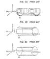
- In the magnet system of the group 2 the static field direction is parallel to the longitudinal axis of the lying human body, and hence is originally horizontal, but in the magnet system of the group 1 the static field direction is conventionally limited specifically to the direction perpendicular to the lying human body. In the group 1 the static field generating means employing permanent magnets is such as shown in Fig. 3 in which different magnetic poles of the
permanent magnets magnetic yoke 24, setting up a verticalstatic field 25 between the opposing faces of themagnets solenoid coil 26 forthe RF magnetic field is disposed in the staticmagnetic field 25. The axis of thesolenoid coil 26 is extended in a horizontal direction and is perpendicularto thestatic field 25. In the solenoid coil 26 adeck 27 is horizontally disposed in a mannerto be slidable in parallel with the axis of thesolenoid coil 26 and anexaminee 28 lies on thedeck 27. - Since the static field direction is vertical, as mentioned above, the magnet system of the group 1 presents the probem that the surface coil cannot be used with its RF direction held vertical.
- WO-A-84/01226 discloses an apparatus according to the preamble of claim 1. There are provided a plurality of ring magnets each comprising a plurality of segments and the magnetization directions of the respective segments are selected to form a uniform static magnetic field inside the ring magnets which is directed vertically.
- An object of the present invention is to provide an NMR-CT apparatus which has the magnet system of the group 1 capable of using the solenoid coil about three times higher in the RF sensitivity than the saddle-shaped coil and which allows to use the surface coil of the vertical RF direction which is effective for examination of the internal organs or regions near the skin surface.
- In order to use the solenoid coil for the human body lying horizontally, it is necessary only that the static field direction be perpendicular to the longitudinal axis of the human body; namely, the static field direction need not alway be vertical unlike in the past. The NMR-CT apparatus of the present invention has an arrangement which makes the static field direction horizontal and permits an access to the examinee's body in a direction perpendicular to the static field direction in this horizontal plane. The solenoid coil for generating the RF magnetic field is disposed with its axis held perpendicular to the static field direction but parallel to the horizontal direction. The examinee's body is brought into and out of the solenoid coil. Furthermore, provision is made for selectively connecting the surface coil and the solenoid coil to the receiver. High-frequency pulses are applied to the solenoid coil or surface coil and an NMR signal is received by either one of the solenoid coil or surface coil and is supplied to the receiver, and then processed to obtain spatial distribution information, which is displayed as an image. In order to increase S/N of received NMR signal, the NMR signals from both the solenoid coil and surface coil may be supplied to the receiver.
- Means for generating the static magnetic field may preferably be formed by a plurality of magnet rings each of which comprises a plurality of permanent magnet blocks disposed in the form of a ring so that they provide magnetic fields of substantially one direction within the magnet ring. The magnet rings are arranged side by side with their axes held in agreement with one another to extend in the horizontal direction. It is preferableto provide means for adjusting the position of each magnet block in the radial direction of each magnet ring, in the skew direction aboutthat radial direction and in the tangential direction.
- The invention is set out in Claim 1.
-
- Fig. 1 is a block diagram illustrating the general arrangement of an NMR-CT apparatus;
- Figs. 2A through 2C are perspective views showing various examples of surface coils;
- Fig. 3 is a front view showing the relationships between the static magnetic field, the RF solenoid coil and the examinee's body in a prior art NMR-CT apparatus;
- Fig. 4 is a perspective view showing, by way of example, the relative arrangement of static field generating device gradient field generating means, a solenoid coil and a deck for the examinee which are principal parts of the apparatus of the present invention;
- Fig. 5 is a perspective view showing the interior of a static field generating device used in the apparatus depicted in Fig. 4;
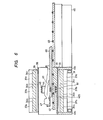
- Fig. 6 is a longitudinal-sectional view of the apparatus of Fig. 4 taken along the axis of the static field generating device, with an examinee held therein;
- Fig. 7 is a diagram showing an open end portion of the apparatus of Fig. 4;
- Fig. 8A is a perspective view illustrating an example of the shape of a
coil 39z for generating a Z-direction gradient field; - Fig. 8B is a perspective view illustrating an example of the shape of a
coil 39y for generating a Y-direction gradient field; - Fig. 8C is a perspective view illustrating an example of the shape of a
coil 39x for generating an X-direction gradient field; - Fig. 9 is a perspective view illustrating the general arrangement of the static field generating device with its cover taken off;
- Fig. 10A is a cross-sectional view taken on the axis of a shaft, illustrating an example of a radial direction
adjustment wedge mechanism 75; - Fig. 10B is a cross-sectional view taken on the line I-I in Fig. 10A;
- Fig. 11 is an exploded perspective view of part of the wedge mechanism shown in Figs. 10A and 10B;
- Fig. 12 is a cross-sectional view taken on the line II-II in Fig. 11, showing a
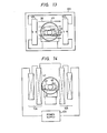
wedge mechanism 87; - Fig. 13 is a diagram corresponding to Fig. 3, illustrating an example of the present invention in which the static field is generated by a permanent magnet having its two poles disposed opposite; and
- Fig. 14 is a diagram corresponding to Fig. 13, illustrating another example of the present invention which employs resistive magnets for generating the static field.
- Figs. 4 to 7 illustrate an embodiment of the present invention. A static magnetic
field generating device 32 is mounted on amount 31. In this embodiment the static field is generated by a permanent magnet assembly through use of a technique disclosed in United States Patent No. 4,498,048. As depicted in Fig. 4 to 6, threemagnet rings arrows 35, developing a horizontal staticmagnetic field 36 inside the magnet ring. The magnet rings 34a, 34b and 34c are respectively secured to magnet support frame means 37a, 37b and 37c outside thereof and the magnet support frame means are fixedly mounted on themount 31, as shown in Fig. 4. - As illustrated in Figs. 5 and 6, a
bobbin 38 is disposed inside the magnet rings 34a, 34b and 34c coaxially therewith and agradient field coil 39 is wound on thebobbin 38. Both ends of thebobbin 38 project outwardly of the magnet rings 34a and 34c and are held onsupport bases gradient field coil 39 is comprised of acoil 39z for generating a Z-direction gradient field the intensity of which varies in a direction parallel to the axis of thebobbin 38, acoil 39y for generating a Y-direction gradient field the intensity of which varies in the Y-direction and acoil 39x for generating an X-direction field the intensity of which varies in the X-direction. Thecoil 39z is wound, for instance, in such a form as shown in Fig. 8A and its particulars are disclosed, for example, in Japanese Patent Application Laid Open No. 15749/84. Thecoils coil 39z, for example, in such forms as shown in Figs. 8b and 8C, respectively. Their winding configurations are described in detail in Japanese Patent Application Laid Open No. 57140/80. These gradient field are all produced in the Z-direction. - As depicted in Figs. 5 and 6, a
rail 42 is fixedly mounted on the bottom of thebobbin 38 inside thereof to extend in the Z-direction. Aslot 42S is cut in therail 42 to extend from one end to the center thereof in the Z-direction and asolenoid coil 43 is disposed inside thebobbin 38, passing through theslot 42S. Thesolenoid coil 43 is wound on abobbin 44 with its axis held in parallel to the Z-axis and is positioned corresponding to themagnet ring 34b. Thebobbin 44 is detachably secured to therail 42. - Substantially in contact with the other end of the
rail 42 is provided abed 45 with its top surface almost flash with that of therail 42. Acarriage 46 for carrying anexaminee 47 is mounted on thebed 45 in a manner to be slidable into and out of thebobbin 38. For easy movement of thecarriage 46rollers 48 are attached to therail 42 and thebed 45 as required. Thus theexaminee 47 is brought into and out of thebobbin 38 in a direction perpendicular to the horizontal staticmagnetic field 36 as shown in Fig. 7 so that thestatic field 36 is applied perpendicularly to the longitudinal axis of the examinee's body. Arecess 51 is made in thecarriage 46 for receiving therein asurface coil 49, as required, which allows easy positioning of the examinee's body relative to thesurface coil 49 before inserting the body into thebobbin 38. - Fig. 9 shows a practical arrangement of the static
field generating device 32, wherein each of the magnet support frame means 37a, 37b, 37c is formed by a pair of parallel ring plates 59 and 61 and eachmagnet block 33 is mounted to the parallel ring plates via position adjusting means as will be explained hereinafter. The magnet blocks are each produced by binding a number of small magnet pieces in combination. In order to establish a homogeneous magnetic field over as large a space as possible, provision is made for adjusting the position of each magnet ring in its axial direction, the position of eachmagnet block 33 in the radial and tangential directions of the magnet ring and angular position of rotaton of the magnet block 33 (i.e. skew of the magnet block 33) about an axis in the radial direction of the magnet ring. The magnet support frame means 37a, 37b and 37c are loosely threaded withcommon coupling rods 53 andnuts 54 are threadedly engaged with thecoupling rods 53 to clamp each support frame means on both sides thereof, fixing it in position. By adjusting the positions of the magnet rings 34a, 34b and 34c on the magnet support frame means (37a, 37b, 37c with the nuts 54 loosened, the relative positions of the magnet rings 34a, 34b, 34c in the Z-direction can be adjusted. - As depicted in Fig. 9, there are provided a plurality of radial adjusting means 75,89 between each pair of ring plates 59, 61 to fixedly connect them with each other. In addition, tangential/skew adjusting means 87, 88 are fixedly mounted to each pair of the ring plates on both outer side thereof in a corresponding relation to the respective magnet blocks of each magnet ring. In the illustrated embodiment the radial adjusting means 75 for each
magnet block 33 of theinner magnet ring 34b is formed as a wedge type adjusting mechanism. Figs. 10A,10Band 11 show an example of the wege type radial adjustment mechanism. An engagingring 57 is mounted on aback plate 56 of themagnet block 33 and arod 58 is engaged at one end thereof with the engagingring 57 through itsflange 58a so that therod 58 is rotatably mounted on themagnet block 33. As will be understood from Figs. 9 to 11, the pair ofopposed ring plates wedge plates magnet block 33. Theabovementioned rod 58 is received inholes wedge plates rod 58 has an engagingflange 64 formed integrally therewith between thewedge plates coupling plate 71 and a pair of lower wedge bars 67, 68 are similarly fixed to lower side corners of acoupling plate 72. The thinner ends of the wedge bars 65, 66 and 67, 68 are connected to the upper and lower ends of theopposite coupling plates wedge frame 70 having rectangular guide apertures 6Ga and 6Gb defined between the wedge bars 65 and 67 and between the wedge bars 66 and 68. Thewedge frame 70 is slidably interposed between the upper andlower wedge plates rod 58 is engaged with thewedge frame 70 to extend through between the wedge bars 65 and 66 and between the wedge bars 66 and 68, with radially opposite parts of the engagingflange 64 being slidably disposed in the guide apertures 6Ga, 6Gb. Thecoupling plates bolts flange 64. In this way, a radially adjustingwedge mechanism 75 is formed. - When turning the
bolt 73 to urge it against the engagingflange 64 after turning thebolt 74 to release itself from theflange 64 in Fig. 10A, thewedge frame 70 is pulled out in a direction in which thecoupling plate 71 moves away from a center axis of therod 58. Since thewedge plates ring plates flange 64 is pushed up to move therod 58 and themagnet block 33 in a direction opposite from the arrow β, that is, radially of themagnet ring 34b away from its axis. Conversely, when thebolt 74 is turned to be urged against the engagingflange 64 with thebolt 73 disengaged therefrom, themagnet block 33 moves in a direction of the arrow β. In this way, the position of themagnet block 33 can be adjusted radially thereof. - The radially adjusting wedge mechanism permits fine control but is somewhat complex in structure. The outer magnet rings 34a and 34c do not call for such fine control as is needed for the
magnet ring 34b sandwiched therebetween. That is, adjustment of themagnet ring 34b, even if slight, will exert a great influence. From this viewpoint, only a simple bolttype adjustment mechanism 89 is employed in place of the radial adjustingwedge mechanism 75 for each magnet block in the outer magnet rings 34a, 34c as shown in Fig. 9. The bolttype adjustment mechanism 89 has an arrangement in which a threadedrod 92 is screwed into a hole made in adisk 93 mounted oncoupling plate 91 joining the pair of ring plates (59a, 61a; 59c, 61 c) and are rotatably connected at one end to the magnet blocks 33. By turning the threadedrods 92, the magnet blocks 33 are moved back and forth radially of the magnet ring. - The tangential/skew adjusting means 87, 88 is provided in association with each
magnet block 33 on outer sides of each pair ring plates 59, 61 as shown in Fig. 9 and will be explained hereinafter with respect to Figs. 10B and 12. On the outside of the ring plate 61 opposite from therod 58 is fixedly mounted awedge case 76 above theback plate 56 of themagnet block 33, as depicted in Figs. 10B and 12. Thewedge case 76 is open on the side of themagnet block 33 and has disposed therein an engagingwedge piece 77. In thewedge case 76wedges case 76 and the engagingwedge piece 77.Bolts wedges wedge case 76 in alignment with thewedges bolts wedge case 76 by means ofnuts hole 85 is made in the larger end face of the engagingwedge piece 77 adjacent theback plate 56 and a pin planted on theback plate 56 is slidably received in the engaginghole 85. Thus the tangential/skew adjusting means 87 is constructed as a wedge mechanism. In a similar mannerthe tangential/skew adjusting means 88 is constructed as a wedge mechanism. - In Fig. 12, in the case where the
bolt 82 is turned to move thewedge 79 away from themagnet block 33 to loosen the engagement, and then thebolt 81 is turned to move thewedge 78 toward themagnet block 33, the engagingwedge piece 77 is driven to move thepin 86 and themagnet block 33 to the right-hand side, i.e. in a direction of the arrow a. Conversely, when thewedge 79 is pushed down after thewedge 78 is pulled up away from themagnet block 33, the engagingwedge piece 77 is driven to shift thepin 86 and themagnet block 33 in a direction opposite from the arrow a. - The
wedge mechanism 88 works in a manner similar to that of thewedge mechanism 87. Accordingly, by concurrent adjustment of the bothwedge mechanisms magnet block 33 in the direction of the arrow a or in the opposite direction, it is possible to adjust the position of themagnet block 33 in the tangential direction of themagnet ring 34b. Furthermore, by adjusting the bothwedge mechanisms magnet block 33 can be skewed about therod 58. - According to our experiment in which the magnet rings 34a, 34b and 34c were each comprised of eight magnet blocks 33, each of which was produced by binding a number of rare earth iron magnets (measuring 50x30x20 mm) of Nd-Fe-B series whose residual magnetism was in the range of 12.0 to 12.6 K gausses, a homogeneous magnetic field with a difference between maximum and minimum field intensities held within 30 ppm was obtained inside a cylindrical plane with a radius of 175 mm from the center of each magnet ring. With the arrangement of the present invention, a homogeneous magnetic field can be obtained in a wide space. In particular, sufficiently high resolution can be obtained even if magnetic fields are applied to the examinee's body horizontally along the longer diameter of the elliptical cross-section of the body.
- With the arrangement shown in Figs. 4 to 7, the examinee lying on his back or stomach on the
carriage 46 is brought into and out of thebobbin 38, that is, along the axial direction of thesolenoid coil 43 for generating the RF magnetic field. Accordingly, an NMR signal of high SN ratio can be obtained through utilization of thesolenoid coil 43, so that a tomographic image of theexaminee 47 can be produced. It is also possible to exchange thesolenoid coil 43 with another one of a diameter corresponding to the size of a particular part of the examinee's body such as the head, the trunk or the like. When it is desired to limit the examination to a small specified region of the examinee's body, thesurface coil 49 of a solenoid type such as shown in Fig. 2B can be placed under or on the examinee'sbody 47 to obtain the NMR signal from the target region. - The shape of the surface coil can be selected in accordance with the surface configuration of a particular region of examination. For example, in the case of examining the breast, such a spiral surface coil of a cone-shape as shown in Fig. 2C may be used. In any case, since the static magnetic field is horizontal, the
surface coil 49 can be disposed with its RF direction held vertically, permitting effective examination of various parts of the examinee's body. Moreover, S/N of the received signal can be further improved by obtaining NMR signals from both thesolenoid coil 43 and thesurface coil 49 and supplying them to thereceiver 17. - The static field generating means is not limited specifically to the magnet device previously described but may also be such, for example, as shown in Fig. 13. In Fig. 13 different magnetic poles of permanent magnets 101 and 102 are disposed in opposing relation so that the horizontal static
magnetic field 36 is set up therebetween. In thestatic field 36 is disposed the RF field generatingsolenoid coil 43, together with a gradient field generating coil though not shown. The axis of thesolenoid coil 43 is horizontal and perpendicularly crosses the direction of thestatic field 36. Thecarriage 46 is disposed so that it is slid into and out of thesolenoid coil 43 in parallel to its axis. That is, the examinee is brought into and out of the static field perpendicularly thereto from the horizontal direction. The magnets 101 and 102 are interconnected via amagnetic yoke 103. That is, the opposed magnets 101 and 102 are disposed on the left and right of the examinee'sbody 47 so that thestatic field 36 is horizontally directed and is perpendicular to the longitudinal axis of the examinee'sbody 47. - With such an arrangement, the
solenoid coil 43 can be employed for the purpose of obtaining a uniform tomographic image of the entire region of the head or the body of theexaminee 47. In addition, in the case of limiting examination to a specified narrow region, it is also possible to place thesurface coil 49 under or on the examinee'sbody 47. - In the case of using resistive magnets, an arrangement such as depicted in Fig. 14 is employed, in which static field coils 104 and 105 are arranged horizontally in opposing relation, so that their axes are horizontal. The RF field generating
solenoid coil 43 and thecarriage 46 are disposed between the static field coils 104 and 105. The static field coils 104 and 105 are excited by apower supply 106. The gradient field generating coil is also provided, though not shown. - As described above, according to the NMR-CT apparatus of the present invention, a solenoid coil of high sensitivity is used and a surface coil can be employed with its RF direction held vertical. Accordingly, it is possible to use an RF coil most suitable for a particular region for examination at all times.
- It will be apparent that many modifications and variations may be effected without departing from the scope of the novel concepts of the present invention.
Claims (16)
Applications Claiming Priority (2)
| Application Number | Priority Date | Filing Date | Title |
|---|---|---|---|
| JP1984201444U JPS61115958U (en) | 1984-12-30 | 1984-12-30 | |
| JP201444/84 | 1984-12-30 |
Publications (3)
| Publication Number | Publication Date |
|---|---|
| EP0187389A2 EP0187389A2 (en) | 1986-07-16 |
| EP0187389A3 EP0187389A3 (en) | 1987-05-27 |
| EP0187389B1 true EP0187389B1 (en) | 1989-05-31 |
Family
ID=16441186
Family Applications (1)
| Application Number | Title | Priority Date | Filing Date |
|---|---|---|---|
| EP85116651A Expired EP0187389B1 (en) | 1984-12-30 | 1985-12-30 | Apparatus for obtaining image information through use of a nuclear magnetic resonance signal |
Country Status (4)
| Country | Link |
|---|---|
| US (1) | US4727327A (en) |
| EP (1) | EP0187389B1 (en) |
| JP (1) | JPS61115958U (en) |
| DE (1) | DE3570757D1 (en) |
Families Citing this family (38)
| Publication number | Priority date | Publication date | Assignee | Title |
|---|---|---|---|---|
| US4679022A (en) * | 1985-12-27 | 1987-07-07 | Sumitomo Special Metal Co. Ltd. | Magnetic field generating device for NMR-CT |
| JPS6350003A (en) * | 1986-08-20 | 1988-03-02 | Toshiba Corp | Magnet device for magnetic resonance imaging apparatus |
| US4841249A (en) * | 1986-10-28 | 1989-06-20 | Siemens Aktiengesellschaft | Truncated cone shaped surface resonator for nuclear magnetic resonance tomography |
| NL8602821A (en) * | 1986-11-07 | 1988-06-01 | Philips Nv | METHOD AND APPARATUS FOR DETERMINING CORRECTED MRI SURFACE SPOOL IMAGE |
| JPS63154170A (en) * | 1986-12-19 | 1988-06-27 | 株式会社東芝 | Magnetic resonance imaging apparatus |
| FR2612641B1 (en) * | 1987-03-19 | 1989-06-09 | Oreal | APPARATUS FOR EXAMINING A BODY BY NUCLEAR MAGNETIC RESONANCE BY SLOW AND FAST METHODS, PARTICULARLY FOR EXAMINING THE SURFACE LAYER OF THIS BODY, DEVICE FOR CREATING A GRADIENT OF MAGNETIC FIELD FOR SUCH APPARATUS, AND APPLICATION TO THE SAME HUMAN BODY SKIN IMAGING |
| FR2623908A1 (en) * | 1987-11-27 | 1989-06-02 | Thomson Cgr | Nuclear magnetic resonance imaging apparatus and pick-up antenna for such an apparatus |
| US4857846A (en) * | 1988-03-31 | 1989-08-15 | The Regents Of The University Of California | Rapid MRI using multiple receivers producing multiply phase-encoded data derived from a single NMR response |
| US4949043A (en) * | 1988-04-18 | 1990-08-14 | Resonance Research Inc. | Apparatus for rendering a static magnetic field uniform |
| US5207224A (en) * | 1988-12-09 | 1993-05-04 | Picker International, Ltd. | Magnetic resonance apparatus |
| GB2226138B (en) * | 1988-12-09 | 1993-01-06 | Picker Int Ltd | Magnetic resonance apparatus |
| DE3907927A1 (en) * | 1989-03-11 | 1990-09-20 | Bruker Analytische Messtechnik | MAGNETIC SYSTEM |
| US5023554A (en) * | 1989-05-22 | 1991-06-11 | The Reagents Of The University Of California | Fringe field MRI |
| US5199435A (en) * | 1989-06-13 | 1993-04-06 | Kabushiki Kaisha Toshiba | Magnetic resonance imaging system |
| JP2637336B2 (en) * | 1992-06-30 | 1997-08-06 | 株式会社島津製作所 | Magnetic resonance tomography equipment |
| RU2106748C1 (en) * | 1993-12-21 | 1998-03-10 | Юрий Алексеевич Бауров | Method for information transmission and claims for device which implements said method |
| JP3676853B2 (en) * | 1994-08-03 | 2005-07-27 | コーニンクレッカ フィリップス エレクトロニクス エヌ ヴィ | MR method for determining nuclear magnetization distribution by surface coil arrangement |
| US6489872B1 (en) | 1999-05-06 | 2002-12-03 | New Mexico Resonance | Unilateral magnet having a remote uniform field region for nuclear magnetic resonance |
| FR2795524B1 (en) * | 1999-06-23 | 2001-08-03 | Commissariat Energie Atomique | PORTABLE NMR MEASURING DEVICE |
| JP3655783B2 (en) * | 1999-10-05 | 2005-06-02 | ジーイー横河メディカルシステム株式会社 | Puncture needle support, RF coil, magnetic resonance signal measuring apparatus, and magnetic resonance imaging apparatus |
| US6940378B2 (en) * | 2001-01-19 | 2005-09-06 | Halliburton Energy Services | Apparatus and method for magnetic resonance measurements in an interior volume |
| JP2003329756A (en) * | 2002-05-08 | 2003-11-19 | Hitachi Ltd | Ultrahighsensitivity nuclear magnetic resonance imaging apparatus |
| US6850140B1 (en) * | 2003-09-10 | 2005-02-01 | Magnetic Technologies Corporation | Layered magnets and methods for producing same |
| US7199689B1 (en) * | 2006-01-09 | 2007-04-03 | Brk Wireless Company, Inc | High field NMR permanent magnetic structure |
| JP5063107B2 (en) * | 2006-12-28 | 2012-10-31 | 株式会社日立製作所 | Magnetic resonance inspection equipment |
| US8219176B2 (en) * | 2007-03-08 | 2012-07-10 | Allegheny-Singer Research Institute | Single coil parallel imaging |
| US7541808B2 (en) * | 2007-04-11 | 2009-06-02 | Allegheny-Singer Research Institute | Rapid MRI dynamic imaging using MACH |
| US8688193B2 (en) * | 2008-06-26 | 2014-04-01 | Allegheny-Singer Research Institute | Magnetic resonance imager, method and program which continuously applies steady-state free precession to k-space |
| EP2144076B1 (en) * | 2008-07-07 | 2012-05-23 | RWTH Aachen | Segmented ring magnet arrangement for providing a magnetic field |
| US7834629B2 (en) * | 2008-09-11 | 2010-11-16 | Allegheny-Singer Research Institute | Hybrid MRI and method |
| US8131046B2 (en) * | 2008-10-29 | 2012-03-06 | Allegheny-Singer Research Institute | Magnetic resonance imager using cylindrical offset region of excitation, and method |
| US8198892B2 (en) * | 2009-04-22 | 2012-06-12 | Allegheny-Singer Research Institute | Steady-state-free-precession (SSFP) magnetic resonance imaging (MRI) and method |
| FR2949602A1 (en) * | 2009-08-28 | 2011-03-04 | Commissariat Energie Atomique | CYLINDRICAL PERMANENT MAGNET DEVICE PRODUCING A MAGNETIC FIELD CONTROLLED AT A DISTANCE FROM ITS SURFACE |
| US8405394B2 (en) * | 2009-10-20 | 2013-03-26 | Allegheny-Singer Research Institute | Targeted acquisition using holistic ordering (TACHO) approach for high signal to noise imaging |
| US20110215805A1 (en) * | 2010-03-03 | 2011-09-08 | Allegheny-Singer Research Institute | MRI and method using multi-slice imaging |
| US9910115B2 (en) * | 2012-10-22 | 2018-03-06 | The General Hospital Corporation | System and method for portable magnetic resonance imaging using a rotating array of magnets |
| FR2997197B1 (en) * | 2012-10-23 | 2016-02-12 | Commissariat Energie Atomique | METHOD AND DEVICE FOR MAINTAINING AND ADJUSTING PERMANENT MAGNETS INCLUDED IN AN NMR SYSTEM |
| US11320500B2 (en) * | 2018-12-28 | 2022-05-03 | Commissariat à l'énergie atomique et aux énergies alternatives | Cryogenic device for magnetic resonance imagery scanner and magnetic resonance imagery assembly comprising such cryogenic device |
Family Cites Families (7)
| Publication number | Priority date | Publication date | Assignee | Title |
|---|---|---|---|---|
| US4411270A (en) * | 1978-11-20 | 1983-10-25 | Damadian Raymond V | Apparatus and method for nuclear magnetic resonance scanning and mapping |
| JPS576347A (en) * | 1980-06-13 | 1982-01-13 | Toshiba Corp | Nuclear magnetic resonator |
| CA1198162A (en) * | 1982-09-23 | 1985-12-17 | Robert D. Hay | Nmr imaging apparatus |
| US4480228A (en) * | 1982-10-15 | 1984-10-30 | General Electric Company | Selective volume method for performing localized NMR spectroscopy |
| IL70982A0 (en) * | 1983-03-07 | 1984-05-31 | Gen Electric | Superconducting magnet having a structure for ringshaped superconductive coils |
| US4590427A (en) * | 1983-03-28 | 1986-05-20 | The United States Of America As Represented By The United States Department Of Energy | Nuclear magnetic resonance apparatus having semitoroidal rf coil for use in topical NMR and NMR imaging |
| DE3340337A1 (en) * | 1983-11-08 | 1985-05-15 | Siemens AG, 1000 Berlin und 8000 München | HIGH-FREQUENCY DEVICE OF A NUCLEAR RESONANCE APPARATUS |
-
1984
- 1984-12-30 JP JP1984201444U patent/JPS61115958U/ja active Pending
-
1985
- 1985-12-27 US US06/814,123 patent/US4727327A/en not_active Expired - Lifetime
- 1985-12-30 DE DE8585116651T patent/DE3570757D1/en not_active Expired
- 1985-12-30 EP EP85116651A patent/EP0187389B1/en not_active Expired
Also Published As
| Publication number | Publication date |
|---|---|
| DE3570757D1 (en) | 1989-07-06 |
| JPS61115958U (en) | 1986-07-22 |
| EP0187389A3 (en) | 1987-05-27 |
| EP0187389A2 (en) | 1986-07-16 |
| US4727327A (en) | 1988-02-23 |
Similar Documents
| Publication | Publication Date | Title |
|---|---|---|
| EP0187389B1 (en) | Apparatus for obtaining image information through use of a nuclear magnetic resonance signal | |
| FI88081C (en) | NMR RF-SPOLE | |
| US6906518B2 (en) | RF coil system for magnetic resonance imaging apparatus | |
| US5600245A (en) | Inspection apparatus using magnetic resonance | |
| EP0314262B1 (en) | MRI system with open access to patient image volume | |
| US6624633B1 (en) | Disjunct MRI array coil system | |
| EP0084946B1 (en) | Apparatus for generating or detecting field components in a magnetic resonance system | |
| US7109712B2 (en) | Method and apparatus for minimizing gradient coil and rf coil coupling | |
| EP0554388B1 (en) | A radio frequency volume resonator for nuclear magnetic resonance | |
| EP0982598B1 (en) | Magnetic resonance system with shim rings | |
| JP4588830B2 (en) | RF coil array device for vertical magnetic field MRI | |
| Kathiravan et al. | A review on potential issues and challenges in MR imaging | |
| US9041398B2 (en) | RF antenna for MRI with a removable conductor | |
| US6278351B1 (en) | Multi-coil MRI magnet | |
| US5382903A (en) | Magnetic resonance apparatus | |
| US20040263170A1 (en) | Magnetic gradient field projection | |
| EP0982599B1 (en) | Magnetic resonance imaging magnet system | |
| JPH11128206A (en) | Magnetic resonance image forming equipment | |
| JP2870641B2 (en) | Magnetic resonance imaging | |
| JP3112474B2 (en) | Magnetic resonance imaging equipment | |
| EP3428672A1 (en) | Staggered parallel transmission radio frequency coil for magnetic resonance imaging | |
| GB2266775A (en) | MRI surface pick-up coil with reduced off-axis sensitivity | |
| JPH05344959A (en) | Testing device utilizing nuclear magnetic resonance | |
| Breneman et al. | 4931759 Magnetic resonance imaging magnet having minimally symmetric ferromagnetic shield | |
| Overweg et al. | 4931735 Superconductive magnet system comprising superconductive cylinders |
Legal Events
| Date | Code | Title | Description |
|---|---|---|---|
| PUAI | Public reference made under article 153(3) epc to a published international application that has entered the european phase |
Free format text: ORIGINAL CODE: 0009012 |
|
| 17P | Request for examination filed |
Effective date: 19851230 |
|
| AK | Designated contracting states |
Kind code of ref document: A2 Designated state(s): DE FR GB |
|
| PUAL | Search report despatched |
Free format text: ORIGINAL CODE: 0009013 |
|
| AK | Designated contracting states |
Kind code of ref document: A3 Designated state(s): DE FR GB |
|
| 17Q | First examination report despatched |
Effective date: 19880121 |
|
| ITF | It: translation for a ep patent filed |
Owner name: HARRIES JOHN |
|
| GRAA | (expected) grant |
Free format text: ORIGINAL CODE: 0009210 |
|
| AK | Designated contracting states |
Kind code of ref document: B1 Designated state(s): DE FR GB |
|
| REF | Corresponds to: |
Ref document number: 3570757 Country of ref document: DE Date of ref document: 19890706 |
|
| ET | Fr: translation filed | ||
| PLBI | Opposition filed |
Free format text: ORIGINAL CODE: 0009260 |
|
| 26 | Opposition filed |
Opponent name: N.V. PHILIPS' GLOEILAMPENFABRIEKEN Effective date: 19900226 |
|
| PLBN | Opposition rejected |
Free format text: ORIGINAL CODE: 0009273 |
|
| STAA | Information on the status of an ep patent application or granted ep patent |
Free format text: STATUS: OPPOSITION REJECTED |
|
| 27O | Opposition rejected |
Effective date: 19910507 |
|
| REG | Reference to a national code |
Ref country code: GB Ref legal event code: IF02 |
|
| PGFP | Annual fee paid to national office [announced via postgrant information from national office to epo] |
Ref country code: FR Payment date: 20041208 Year of fee payment: 20 |
|
| PGFP | Annual fee paid to national office [announced via postgrant information from national office to epo] |
Ref country code: DE Payment date: 20041223 Year of fee payment: 20 |
|
| PGFP | Annual fee paid to national office [announced via postgrant information from national office to epo] |
Ref country code: GB Payment date: 20041229 Year of fee payment: 20 |
|
| PG25 | Lapsed in a contracting state [announced via postgrant information from national office to epo] |
Ref country code: GB Free format text: LAPSE BECAUSE OF EXPIRATION OF PROTECTION Effective date: 20051229 |
|
| REG | Reference to a national code |
Ref country code: GB Ref legal event code: PE20 |