EP0187089A1 - Apparatus for measuring the flow pressure characteristics of a gas crossing a sample of a product with two faces - Google Patents
Apparatus for measuring the flow pressure characteristics of a gas crossing a sample of a product with two faces Download PDFInfo
- Publication number
- EP0187089A1 EP0187089A1 EP85402464A EP85402464A EP0187089A1 EP 0187089 A1 EP0187089 A1 EP 0187089A1 EP 85402464 A EP85402464 A EP 85402464A EP 85402464 A EP85402464 A EP 85402464A EP 0187089 A1 EP0187089 A1 EP 0187089A1
- Authority
- EP
- European Patent Office
- Prior art keywords
- sample
- output
- flow
- vacuum
- pump
- Prior art date
- Legal status (The legal status is an assumption and is not a legal conclusion. Google has not performed a legal analysis and makes no representation as to the accuracy of the status listed.)
- Granted
Links
Images


Classifications
-
- G—PHYSICS
- G01—MEASURING; TESTING
- G01N—INVESTIGATING OR ANALYSING MATERIALS BY DETERMINING THEIR CHEMICAL OR PHYSICAL PROPERTIES
- G01N15/00—Investigating characteristics of particles; Investigating permeability, pore-volume, or surface-area of porous materials
- G01N15/08—Investigating permeability, pore-volume, or surface area of porous materials
- G01N15/082—Investigating permeability by forcing a fluid through a sample
- G01N15/0826—Investigating permeability by forcing a fluid through a sample and measuring fluid flow rate, i.e. permeation rate or pressure change
Definitions
- the subject of the present invention is an apparatus for measuring the flow-pressure characteristic of a gas passing through a two-sided product sample comprising a sample holder arranged so that one of the faces of the sample is subjected to atmospheric pressure, a pump for applying a vacuum to the other face of the sample, a sensor for measuring said vacuum a sensor for measuring the flow of gas through the sample which results from said vacuum, a setpoint signal generator and means for comparing the output of one of the two sensors and the output of the setpoint signal generator.
- Such a device is in particular used to measure the air permeability of materials used as cigarette paper, or sheathing for a filter, in conformity for example with the international standard ISO 2965 or with the French standard NF V37-010.
- Permeability is the ratio of air flow (volume per unit time) per unit area of the sample to the pressure difference across that sample.
- British patent application No. 2,094,986A describes an apparatus of the above type, in which, however, there is neither a setpoint signal generator, nor means for comparing the output of one of the sensors and the setpoint signal generator output.
- this device means are provided for varying the air flow rate through the sample, constituted in particular by a battery of constant flow devices mounted in parallel, and connecting the sample holder to the pump.
- a valve In series with each device, a valve is mounted and the nominal values of the flows likely to pass through each of the branches are in geometric progression: the first device, when in service, is necessarily traversed by a flow of 1 liter per minute, the second by a flow of 2 liters per minute, the third by a flow of 4 liters per minute and so on.
- each permeability measurement is made under specified conditions of depression, for example 0.25 and 1 kilopascal.
- US Pat. No. 4,311,037 provides a setpoint signal generator, means for comparing the output of one of the two sensors and the output output of the setpoint signal generator, and a speed pump. of variable rotation, the speed of rotation of which is controlled by the output of the comparison means.
- the present invention overcomes these drawbacks. It firstly relates to an apparatus of the above type, characterized in that it further comprises a valve, interposed between said sample and said pump for controlling said flow, controlled continuously by the outlet said comparison means.
- the measurement time is reduced to a minimum because the vacuum reaches the value specified by the operator using the setpoint signal generator in a very short time.
- said comparison means comprise an electronic circuit, comprising a subtractor assembly, followed by an amplification chain comprising a proportional response amplifier, an integral response amplifier and a derivative response amplifier, these three amplifiers being connected in parallel, said chain being followed by a power amplifier to control said valve.
- the apparatus comprises, interposed between said valve and said pump, a bypass connected to the atmosphere via an auxiliary valve to cancel said vacuum while the pump remains in operation.
- the sample change can then be very quick.
- said flow sensor comprises a multicapillary pressure drop element and a differential pressure sensor.
- the flow measurement is then linear over a very wide range of flow rates.
- the apparatus according to the invention can also be arranged so that the output of the sensor measuring the air flow is applied to the comparison means, so that a particular value of flow, specified using the setpoint signal generator , is carried out, for example for compliance with a test recommendation different from the standards cited.
- a sample of cigarette paper having an internal face and an external face, and whose permeability is to be measured, is placed in a sample holder 2.
- the sample holder 2 consists of a fixed metal part 3 open on one side, and a movable metal part 4 open on both sides resting on the fixed part 3 by interposition of a silicone elastomer seal, so as not to deform or mark the sample which must be placed between the metal parts 3 and 4.
- the metal parts 3 and 4 define a measuring surface of determined shape and dimensions.
- the external face of the sample 1 is placed on the side of the moving part 4, which leaves it subjected to atmospheric pressure P.
- the fixed part 3 is in communication with a conduit 5.
- the duct 5 is connected to a pump 9 via a filter 6, a multicapillary pressure drop element 7, and a continuously controlled control valve 8.
- the multicapillary pressure drop element 7 is provided with two outputs 71 and 72 connected by two conduits 73 and 74 to the two inputs 75 and 76 with a differential pressure sensor 77 with electrical output. This output is connected to an electronic display circuit 78.
- a bypass 10 is connected to the conduit 5 between the valve 8 and the pump 9.
- the bypass 10 is connected to the atmosphere by means of an auxiliary valve 11.
- the p ⁇ .ècefixè 3 is also in communication with a conduit 31, connected to an input 32 of a differential pressure sensor 34 with electrical output.
- the other input 33 of the sensor 34 is subjected to atmospheric pressure P.
- the electrical output of the sensor 34 is connected on the one hand to an electronic display circuit 35 and on the other hand to an input terminal 36 of an electronic valve control circuit 100.
- the electrical output of a setpoint signal generator 40 controllable by an operator is connected to an input terminal 41 of the electronic valve control circuit 100.
- the winding 81 of the continuously controlled control valve 8 is connected with two outputs 82 and 83 of the electronic valve control circuit 100.
- the input terminal 41 is connected to the input plus of an operational amplifier, hereinafter designated by AO, 110 mounted as a follower, the output of which is connected to ground by l 'via a relay contact 112 and a resistor 111 and at the input less than an AO 130 via a resistor 131.
- AO operational amplifier
- the input terminal 36 is connected via a resistor 121 to the input minus of an AO 120 whose input plus is grounded by a resistor 123.
- the cursor of a potentiometer 124 of which the ends are connected to ground and to a negative supply voltage -V is connected to the minus input of the AO 120 by a resistor 122.
- a potentiometer 125 is placed between the output and the minus input of the AO 120.
- the output signal from AO 120 is connected to the input less than..AO 130 by a resistor 132.
- Entrance over the A.O. 130 is earthed by a resistor 133.
- a resistor 134 is placed between the negative input and the output of the A.O. 130.
- the exit from the A.O. 130 is connected to the inputs less than three AO 140, 150 and 160, via three resistors 141, 151 and 161 respectively.
- the inputs plus of the three A.O. 140, 150 and 160 are grounded by three resistors 142, 152 and 162 respectively.
- the outputs of the three A.O. 140, 150 and 160 are connected to the input minus of an A.O. 180 by three resistors 144, 154 and 164 respectively.
- a resistor 143 is placed between the minus input and the output of the A.O. 140.
- a capacitor 153 is placed between the negative input and the output of the A.O. 150.
- Entrance minus the A.O. 160 is connected to the output of an A.O. 175 via a resistor 163.
- a capacitor 179 in series with a resistor 178 is placed between the minus input and the output of the A.O. 175.
- the entrance to the A.O. 175 is earthed by a resistor 176.
- Resistor 177 connects the output of an A.O. 167 to the minus input of the A.O. 175.
- a resistor 168 is placed between the minus input and the output of AO 167.
- a resistor 165 connects the output of AO 160 and the minus input of AO 167.
- the plus input of AO 167 is grounded by a resistor 166.
- Entrance over the A.O. 180 is earthed by a resistor 182.
- a resistor 181 connects the negative input and the output of the A.O. 180.
- the exit from the A.O. 180 is connected to the minus input of Jun A.O. 190 by a resistor 191.
- a positive supply voltage V is connected to the minus input of A.O. 190 by a resistance 193.
- a resistance 194 connects the minus input and the output of the A.O. 190.
- the exit from the A.O. 190 is connected to the base of a power transistor 195 by a resistor 197.
- the collector of transistor 195 is connected to the positive supply voltage V by a resistor 198.
- a resistor 196 is mounted in parallel on the base emitter junction of transistor 195.
- the emitter of transistor 195 is connected to the output terminal 83.
- the output terminal 82 is connected to the negative supply voltage -V.
- a diode 199 connects the terminals 82 and 83.
- the power supplies delivering the supply voltages + V and -V have not been shown. They are of classic design.
- the setpoint signal generator 40 consists of a potentiometer 42, the ends of which are connected to ground and to the positive supply voltage V.
- the voltage on the movable cursor constitutes the setpoint signal applied to terminal 41.
- the apparatus according to the invention which has just been described, operates as follows.
- valve 8 is closed because the contact 112 is open, which causes a zero set value, and the valve 11 is open (by a control electronics not shown) in order to ensure zero vacuum on the sample while allowing the pump 9 to remain in operation.
- the operator sets the setpoint signal generator 40 to a certain value applied to terminal 41 of circuit 100.
- the vacuum to which the sample 1 is subjected is zero , and the signal applied to terminal 36 of circuit 100 is zero.
- Circuit 100 operates as follows.
- the A.O. 110 is mounted as a follower and the A.O. 120 in inverter, shifter and level adapter.
- the output of the summing reversing amplifier 130-134 varies as the difference between the signal representative of the measured vacuum applied to terminal 36 and the setpoint signal applied to terminal 41.
- the output of amplifier 130 -134 is applied to the input of the chain constituted by the parallel connection of an inverting amplifier 140-144 with proportional response, of an inverting amplifier 150-154 with integral response and of an inverting amplifier 160-179 with derived response.
- the output of this chain consists of the output of the inverting summator 180-182, and it controls, via the inverting amplifier, shifter and level adapter 190-194, a power stage 195-198 to control the winding 81, of the continuously controlled control valve 8, winding protected by the diode 199, in a direction such that the valve opens when the difference between the signal representative of the measured vacuum and the setpoint signal is negative.
- the flow can be measured using the multicapillary pressure drop element 7 whose pressure-flow characteristic is strictly linear, and calculate the permeability of the sample.
- the filter 6 protects the multi-capillary pressure drop element 7.
- an automatic zeroing is provided before each measurement in the display system 78.
- the residual voltage present is stored in memory at the output of the sensor 77, to permanently subtract it, thereafter, from the gross result of the measurement.
- the storage is carried out, as shown in FIG. 4, by means of a clock pulse generator 315, which advances a counter 313, followed by a digital-analog converter 312 whose output voltage is compared to the residual voltage by a comparator 311, the clock pulses being blocked by a gate 314 when these two voltages are equal.
- an analog voltage equal to the residual voltage just before the measurement, and which can be subtracted by an analog subtractor 310 from the gross result.
- the measurement time of a device conforming to the description is of the order of a second.
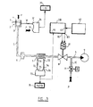
- FIG. 3 shows a variant where the output signal from the sensor 77, representative of the measured flow rate is applied to an input 46 of an electronic circuit. 200 similar in principle to circuit 100, the rest of the system being unchanged. It then becomes possible to make the measurements under the flow conditions set by the setpoint signal generator 40.
- the apparatus of the invention can be applied to the measurement of the flow-pressure characteristics of a gas other than air, and in particular of a gas charged with particles such as smoke.
- the sample considered can be, for example, the filter of a cigarette, or a cigarette.
- the measurements can also be carried out under various conditions of depression (constant, or according to a determined law of temporal variation) or of flow rate, or even relate to the rate of combustion of a cigarette under particular conditions.
- the apparatus of the invention is very well suited to measurements of the continuous type where the sample is a very long strip which passes at a certain speed in front of the sample holder, which has been suitably transformed.
- the rapid response of the apparatus of the invention makes it possible to follow precisely the variations in the characteristics of the sample, even when the latter passes relatively quickly.
Abstract
La présente invention s'applique, par exemple, à la mesure de perméabilité d'un échantillon de matériau perméable à l'air, comme du papier à cigarette par exemple. Un porte-échantillon (1) permet d'exposer la face externe du papier à la pression atmosphérique (P) et la face interne à une dépression créée par une pompe (9), tandis que la valeur de cette dépression et du débit d'air traversant l'échantillon est mesurée (34, 7, 71-77). Un système de commande comprenant une vanne de contrôle à commande continue (8) et un circuit électronique (100) commandé par un signal de consigne (41) et un signal représentatif de la dépression (36) réelle ou du débit réel permet d'obtenir rapidement des conditions de mesures conformes aux exigences de certaines normes et recommandations.The present invention applies, for example, to the measurement of permeability of a sample of breathable material, such as cigarette paper for example. A sample holder (1) makes it possible to expose the external face of the paper to atmospheric pressure (P) and the internal face to a vacuum created by a pump (9), while the value of this vacuum and the flow of air passing through the sample is measured (34, 7, 71-77). A control system comprising a continuously controlled control valve (8) and an electronic circuit (100) controlled by a setpoint signal (41) and a signal representative of the actual vacuum (36) or of the actual flow rate makes it possible to obtain quickly measurement conditions that meet the requirements of certain standards and recommendations.
Description
La présente invention a pour objet un appareil de mesure des caractéristique débit-pression d'un gaz traversant un échantillon de produit à deux faces comprenant un porte-échantillon agencé pour qu'une des faces de l'échantillon soit soumise à la pression atmosphérique, une pompe pour appliquer une dépression sur l'autre face de l'échantillon, un capteur pour mesurer ladite dépression un capteur pour mesurer le débit de gaz à travers l'échantillon qui résulte de ladite dépression, un générateur de signal de consigne et des moyens de comparaison de la sortie de l'un des deux capteurs et de la sortie du générateur de signal de consigne.The subject of the present invention is an apparatus for measuring the flow-pressure characteristic of a gas passing through a two-sided product sample comprising a sample holder arranged so that one of the faces of the sample is subjected to atmospheric pressure, a pump for applying a vacuum to the other face of the sample, a sensor for measuring said vacuum a sensor for measuring the flow of gas through the sample which results from said vacuum, a setpoint signal generator and means for comparing the output of one of the two sensors and the output of the setpoint signal generator.
Un tel appareil est en particulier utilisé pour mesurer la perméabilité à l'air de matériaux utilisés comme papier à cigarette, ou gainage pour filtre, en conformité par exemple avec la norme internationale ISO 2965 ou avec la norme française NF V37-010. La perméabilité est le rapport du débit d'air (volume par unité de temps) par unité de surface de l'échantillon à la différence de pression à travers cet échantillon.Such a device is in particular used to measure the air permeability of materials used as cigarette paper, or sheathing for a filter, in conformity for example with the international standard ISO 2965 or with the French standard NF V37-010. Permeability is the ratio of air flow (volume per unit time) per unit area of the sample to the pressure difference across that sample.
La demande de brevet britannique No. 2 094 986A décrit un appareil du type ci-dessus, dans lequel toutefois, il n'est prévu ni générateur de signal de consigne, ni moyens de comparaison de la sortie d'un des capteurs et de la sortie du générateur de signal de consigne. Dans cet appareil, il est prévu des moyens de variation du débit d'air à travers l'échantillon, constitués en particulier par une batterie de dispositifs à débit constant montés en parallèle, et reliant le porte-échantillon à la pompe. En série avec chaque dispositif est montée une valve et les valeurs nominales des débits susceptibles de parcourir chacune des branches sont en progression géométrique : le premier disositif, lorsqu'il est en service, est nécessairement parcouru par un débit de 1 litre par minute, le second par un débit de 2 litres par minute, le troisième par un débit de 4 litres par minute et ainsi de suite.British patent application No. 2,094,986A describes an apparatus of the above type, in which, however, there is neither a setpoint signal generator, nor means for comparing the output of one of the sensors and the setpoint signal generator output. In this device, means are provided for varying the air flow rate through the sample, constituted in particular by a battery of constant flow devices mounted in parallel, and connecting the sample holder to the pump. In series with each device, a valve is mounted and the nominal values of the flows likely to pass through each of the branches are in geometric progression: the first device, when in service, is necessarily traversed by a flow of 1 liter per minute, the second by a flow of 2 liters per minute, the third by a flow of 4 liters per minute and so on.
Or, pour effectuer les mesures selon la norme ISO 2965, il est nécessaire que chaque mesure de perméabilité soit faite dans des conditions spécifiées de dépression, par exemple 0,25 et 1 kilopascal.However, to perform the measurements according to ISO 2965, it is necessary that each permeability measurement is made under specified conditions of depression, for example 0.25 and 1 kilopascal.
La quantification des débits réalisables avec l'appareil connu entraine une quantification des dépressions qui ne permet pas, sauf par hasard, de réaliser matériellement les conditions de dépression précédentes. Il est donc nécessaire, avec ce système, de rechercher les combinaisons de dispositifs à débit constant telles que les dépressions mesurées correspondantes encadrent au plus près la valeur spécifiée. La perméabilité pour cette valeur spécifiée est ensuite obtenue par un calcul d'interpolation à partir des valeurs mesurées.The quantification of the flow rates achievable with the known device results in a quantification of the depressions which does not make it possible, except by chance, to materially achieve the preceding depression conditions. It is therefore necessary, with this system, to search for combinations of devices with constant flow such that the corresponding measured depressions frame the specified value as closely as possible. The permeability for this specified value is then obtained by an interpolation calculation from the measured values.
Il en résulte une mesure longue et fastidieuse et dont le résultat est entaché d'une erreur liée à l'interpolation.The result is a long and tedious measurement, the result of which is tainted by an error linked to the interpolation.
Pour pallier ces inconvénients, le brevet US 4 311 037 prévoit un générateur de signal de consigne, des moyens de comparaison de la sortie de l'un des deux capteurs et de la sortie sortie du générateur de signal de consigne, et une pompe à vitesse de rotation variable, dont la vitesse de rotation est commandée par la sortie des moyens de comparaison.To overcome these drawbacks, US Pat. No. 4,311,037 provides a setpoint signal generator, means for comparing the output of one of the two sensors and the output output of the setpoint signal generator, and a speed pump. of variable rotation, the speed of rotation of which is controlled by the output of the comparison means.
Ainsi, lorsqu'un tel appareil est agencé par exemple, pour que la sortie du capteur mesurant la dépression soit appliquée aux moyens de comparaison, il permet d'obtenir en permanence une dépression constante, dont la valeur est égale à la valeur spécifiée à l'aide du générateur de signal de consigne.Thus, when such an apparatus is arranged for example, so that the output of the sensor measuring the depression is applied to the comparison means, it makes it possible to permanently obtain a constant depression, the value of which is equal to the value specified at l using the setpoint signal generator.
Toutefois, un tel appareil, ne peut répondre que lentement à des variations relativement rapides en sortie du générateur de consigne, du fait que la régulation pour obtenir un débit donné, ou une dépression donnée, est obtenue en faisant varier la vitesse de rotation de la pompe. Il en résulte des imprécisions des mesures lorsque celles-ci doivent être faites assez rapidement, ou des risques de voir l'appareil entier en auto-oscillations.However, such an apparatus can only respond relatively slowly to relatively rapid variations at the output of the setpoint generator, owing to the fact that the regulation to obtain a given flow rate, or a given vacuum, is obtained by varying the rotation speed of the pump. This results in inaccuracies in the measurements when they have to be made fairly quickly, or in the risks of seeing the entire device in self-oscillations.
Par ailleurs, avec l'appareil décrit dans le brevet US 4 311 037, le contrôle d'un grand nombre d'échantillons distincts est long et fastidieux, car il est nécessaire d'arrêter la pompe à chaque changement d'échantillon et d'attendre ensuite assez longtemps le rétablissement de la dépression.Furthermore, with the apparatus described in US Pat. No. 4,311,037, checking a large number of separate samples is long and tedious, since it is necessary to stop the pump each time the sample and sample are changed. then wait long enough for recovery from depression.
Enfin, dans cet appareil, la mesure du débit traversant l'échantillon fait intervenir un venturi, c'est-à-dire d'un étranglement dans une conduite. Or un tel dispositif présente une caractéristique débit-pression non linéaire, ce qui limite l'emploi de l'appareil à une gamme relativement étroite de débits si on veut éviter des corrections fastidieuses.Finally, in this device, the measurement of the flow rate passing through the sample involves a venturi, that is to say a constriction in a pipe. However, such a device has a non-linear flow-pressure characteristic, which limits the use of the device to a relatively narrow range of flow rates if it is desired to avoid tedious corrections.
La présente invention pallie ces inconvénients. Elle a tout d'abord pour objet un appareil du type ci-dessus, caractérisé par le fait qu'il comprend, en outre, une vanne, intercalée entre ledit échantillon et ladite pompe pour contrôler ledit débit, commandée de façon continue par la sortie desdits moyens de comparaison.The present invention overcomes these drawbacks. It firstly relates to an apparatus of the above type, characterized in that it further comprises a valve, interposed between said sample and said pump for controlling said flow, controlled continuously by the outlet said comparison means.
Dans l'appareil de l'invention, les variations de la dépression suivent de façon pratiquement instantanée celles du signal de sortie des moyens de comparaison. Le temps de réponse du système est donc très bref.In the apparatus of the invention, the variations in depression follow practically instantaneously those of the output signal of the comparison means. The system response time is therefore very short.
Le temps de mesure est réduit au minimum, car la dépression atteint la valeur spécifiée par l'opérateur à l'aide du générateur de signal de consigne en un temps très court.The measurement time is reduced to a minimum because the vacuum reaches the value specified by the operator using the setpoint signal generator in a very short time.
Selon une caractéristique supplémentaire de l'invention, lesdits moyens de comparaison comportent un circuit électronique, comprenant un ensemble soustracteur, suivi d'une chaîne d'amplification comportant un amplificateur à réponse proportionnelle, un amplificateur à réponse intégrale et un amplificateur à réponse dérivée, ces trois amplificateurs étant montés en parallèle, ladite chaîne étant suivie d'un amplificateur de puissance pour commander ladite vanne.According to an additional characteristic of the invention, said comparison means comprise an electronic circuit, comprising a subtractor assembly, followed by an amplification chain comprising a proportional response amplifier, an integral response amplifier and a derivative response amplifier, these three amplifiers being connected in parallel, said chain being followed by a power amplifier to control said valve.
La précision du système est grande, sans risque d'auto-oscillations.The accuracy of the system is high, without the risk of self-oscillations.
Selon une autre caractéristique de l'invention, l'appareil comprend, intercalé entre ladite vanne et ladite pompe une dérivation reliée à l'atmosphère par l'intermédiaire d'une vanne auxiliaire pour annuler ladite dépression alors que la pompe reste en fonctionnement.According to another characteristic of the invention, the apparatus comprises, interposed between said valve and said pump, a bypass connected to the atmosphere via an auxiliary valve to cancel said vacuum while the pump remains in operation.
Le changement d'échantillon peut alors être très rapide.The sample change can then be very quick.
Selon une autre caractéristique de l'appareil de l'invention, ledit capteur de débit comprend un élément à perte de charge multicapillaire et un capteur de pression différentiel.According to another characteristic of the apparatus of the invention, said flow sensor comprises a multicapillary pressure drop element and a differential pressure sensor.
La mesure de débit est alors linéaire sur une très large gamme de débits.The flow measurement is then linear over a very wide range of flow rates.
L'appareil selon l'invention peut également être agencé pour que la sortie du capteur mesurant le débit d'air soit appliquée aux moyens de comparaison, afin qu'une valeur particulière de débit, spécifiée à l'aide du générateur de signal de consigne, soit réalisée, par exemple pour le respect d'une recommandation d'essai différente des normes citées.The apparatus according to the invention can also be arranged so that the output of the sensor measuring the air flow is applied to the comparison means, so that a particular value of flow, specified using the setpoint signal generator , is carried out, for example for compliance with a test recommendation different from the standards cited.
L'invention sera mieux comprise à l'aide de la description suivante d'une forme de réalisation préférée du système selon l'invention, faite en se référant aux dessins annexés, sur lesquels :
- - la figure 1 représente un schéma de principe de l'appareil selon l'invention;
- - la figure 2 représente un schéma du circuit électronique de commande de vanne et du générateur de signal de consigne de la figure 1;
- - la figure 3 représente un schéma de principe d'une variante de l'appareil selon l'invention; et,
- - la figure 4 représente un schéma de principe du dispositif de mise à zéro automatique de la mesure de débit de l'appareil de la figure 1.
- - Figure 1 shows a block diagram of the apparatus according to the invention;
- - Figure 2 shows a diagram of the electronic valve control circuit and the setpoint signal generator of Figure 1;
- - Figure 3 shows a block diagram of a variant of the apparatus according to the invention; and,
- - Figure 4 shows a block diagram of the device for automatic zeroing of the flow measurement of the device of Figure 1.
En se référant à la figure 1, un échantillon de papier à cigarette, comportant une face interne et une face externe, et dont on veut mesurer la perméabilité est placé dans un porte-échantillon 2. Le porte-échantillon 2 est constitué d'une pièce métallique fixe 3 ouverte d'un côté, et d'une pièce métallique mobile 4 ouverte des deux côtés reposant sur la pièce fixe 3 par interposition d'un joint en élastomère silicone, de façon à ne pas déformer ni marquer l'échantillon qui doit être placé entre les pièces métalliques 3 et 4. Les pièces métalliques 3 et 4 délimitent une surface de mesure de forme et de dimensions déterminées. La face externe de l'échantillon 1 est placée du côté de la pièce mobile 4, qui la laisse soumise à la pression atmosphérique P. La pièce fixe 3 est en communication avec un conduit 5.Referring to FIG. 1, a sample of cigarette paper, having an internal face and an external face, and whose permeability is to be measured, is placed in a
Le conduit 5 est relié à une pompe 9 par l'intermédiaire d'un filtre 6, d'un élément à perte de charge multicapillaire 7, et d'une vanne de contrôle à commande continue 8.The
L'élément à perte de charge multicapillaire 7 est muni de deux sorties 71 et 72 reliées par deux conduits 73 et 74 aux deux entrées 75 et 76 d'un capteur différentiel de pression 77 à sortie électrique. Cette sortie est reliée à un circuit d'affichage électronique 78.The multicapillary
Une dérivation 10 est raccordée au conduit 5 entre la vanne 8 et la pompe 9. La dérivation 10 est reliée à l'atmosphère par l'intermédiaire d'une vanne auxiliaire 11.A
La pï.ècefixè 3 est également en communication avec un conduit 31, relié à une entrée 32 d'un capteur différentiel de pression 34 à sortie électrique. L'autre entrée 33 du capteur 34 est soumise à la pression atmosphérique P. La sortie électrique du capteur 34 est reliée d'une part à un circuit d'affichage électronique 35 et d'autre part à une borne d'entrée 36 d'un circuit électronique de commande de vanne 100.The
La sortie électrique d'un générateur de signal de consigne 40 commandable par un opérateur, est reliée à une borne d'entrée 41 du circuit électronique de commande de vanne 100. L'enroulement 81 de la vanne de contrôle à commande continue 8 est reliée à deux sorties 82 et 83 du circuit électronique de commande de vanne 100.The electrical output of a
En se référant maintenant à la figure 2, la borne d'entrée 41 est reliée à l'entrée plus d'un amplificateur opérationnel, désigné dans la suite par A.O., 110 monté en suiveur, dont la sortie est reliée à la masse par l'intermédiaire d'un contact de relais 112 et d'une résistance 111 et à l'entrée moins d'un A.O. 130 par l'intermédiaire d'une résistance 131.Referring now to FIG. 2, the
La borne d'entrée 36 est reliée par l'intermédiaire d'une résistance 121 à l'entrée moins d'un A.O. 120 dont l'entrée plus est mise à la masse par une résistance 123. Le curseur d'un potentiomètre 124 dont les extrémités sont reliées à la masse et à une tension d'alimentation négative -V est relié à l'entrée moins de l'A.O. 120 par une résistance 122. Un potentiomètre 125 est placé entre la sortie et l'entrée moins de l'A.O. 120. Le signal de sortie de l'A.O. 120 est relié à l'entrée moins de..l'A.O. 130 par une résistance 132.The
L'entrée plus de l'A.O. 130 est mise à la masse par une résistance 133. Une résistance 134 est placée entre l'entrée moins et la sortie de l'A.O. 130.Entrance over the A.O. 130 is earthed by a
La sortie de l'A.O. 130 est reliée aux entrées moins de trois AO 140, 150 et 160, par l'intermédiaire de trois résistances 141, 151 et 161 respectivement. Les entrées plus des trois A.O. 140, 150 et 160 sont mises à la masse par trois résistances 142, 152 et 162 respectivement. Les sorties des trois A.O. 140, 150 et 160 sont reliées à l'entrée moins d'un A.O. 180 par trois résistances 144, 154 et 164 respectivement.The exit from the A.O. 130 is connected to the inputs less than three
Une résistance 143 est placée entre l'entrée moins et la sortie de l'A.O. 140.A
Un condensateur 153 est placé entre l'entrée moins et la sortie de l'A.O. 150.A
L'entrée moins de l'A.O. 160 est reliée à la sortie d'un A.O. 175 par l'intermédiaire d'une résistance 163. Un condensateur 179 en série avec une résistance 178 est placé entre l'entrée moins et la sortie de l'A.O. 175. L'entrée plus de l'A.O. 175 est mise à la masse par une résistance 176.Entrance minus the A.O. 160 is connected to the output of an A.O. 175 via a
Une résistance 177 relie la sortie d'un A.O. 167 à l'entrée moins de l'A.O. 175.Resistor 177 connects the output of an A.O. 167 to the minus input of the A.O. 175.
Une résistance 168 est placée entre l'entrée moins et la sortie de l'A.O. 167. Une résistance 165 relie la sortie de l'A.O. 160 et l'entrée moins de l'A.O. 167. L'entrée plus de l'A.O. 167 est mise à la masse par une résistance 166.A
L'entrée plus de l'A.O. 180 est mise à la masse par une résistance 182. Une résistance 181 relie l'entrée moins et la sortie de l'A.O. 180. La sortie de l'A.O. 180 est reliée à l'entrée moins dJun A.O. 190 par une résistance 191. Une tension d'alimentation positive V est reliée à l'entrée moins de l'A.O. 190 par une résistance 193. Une résistance 194 relie l'entrée moins et la sortie de l'A.O. 190.Entrance over the A.O. 180 is earthed by a resistor 182. A
La sortie de l'A.O. 190 est reliée à la base d'un transistor de puissance 195 par une résistance 197. Le collecteur du transistor 195 est relié à la tension d'alimentation positive V par une résistance 198. Une résistance 196 est montée en parallèle sur la jonction émetteur base du transistor 195. L'émetteur du transistor 195 est relié à la borne de sortie 83. La borne de sortie 82 est reliée à la tension d'alimentation négative -V. Une diode 199 relie les bornes 82 et 83.The exit from the A.O. 190 is connected to the base of a
Pour simplifier la figure, les alimentations délivrant les tensions d'alimentation +V et -V n'ont pas été représentées. Elles sont de conception classique.To simplify the figure, the power supplies delivering the supply voltages + V and -V have not been shown. They are of classic design.
Le générateur de signal de consigne 40 est constitué par un potentiomètre 42 dont les extrémités sont reliées à la masse et à la tension d'alimentation positive V. La tension sur le curseur mobile constitue le signal de consigne appliqué à la borne 41.The
L'appareil selon l'invention, qui vient d'être décrit, fonctionne comme suit.The apparatus according to the invention, which has just been described, operates as follows.
Pendant la phase de mise en place de l'échantillon 1 sur le porte-échantillon 2, la vanne 8 est fermée car le contact 112 est ouvert, ce qui provoque une valeur de consigne nulle, et la vanne 11 est ouverte (par une électronique de commande non représentée) afin d'assurer une dépression nulle sur l'échantillon tout en permettant à la pompe 9 de rester en fonctionnement.During the sample placement phase 1 on the
Lorsque l'échantillon est en place, l'opérateur règle le générateur de signal de consigne 40 à une certaine valeur appliquée sur la borne 41 du circuit 100. Au début de la mesure, la dépression à laquelle est soumis l'échantillon 1 est nulle, et le signal appliqué sur la borne 36 du circuit 100 est nulle.When the sample is in place, the operator sets the
Le circuit 100 fonctionne de la manière suivante. L'A.O. 110 est monté en suiveur et l'A.O. 120 en inverseur, décaleur et adapteur de niveau. Il en résulte que la sortie de l'amplificateur inverseur sommateur 130-134 varie comme la différence entre le signal représentatif de la dépression mesurée appliqué sur la borne 36 et le signal de consigne appliqué sur la borne 41. La sortie de l'amplificateur 130-134 est appliquée à l'entrée de la chaîne constituée par la mise en parallèle d'un amplificateur inverseur 140-144 à réponse proportionnelle, d'un amplificateur inverseur 150-154 à réponse intégrale et d'un amplificateur inverseur 160-179 à réponse dérivée. La sortie de cette chaine est constituée par la sortie du sommateur inverseur 180-182, et elle commande, par l'intermédiaire de l'amplificateur inverseur, décaleur et adaptateur de niveau 190-194 un étage de puissance 195-198 pour piloter l'enroulement 81, de la vanne de contrôle à commande continue 8, enroulement protégé par la diode 199, dans un sens tel que la vanne s'ouvre lorsque la différence entre le signal représentatif de la dépression mesurée et le signal de consigne est négative.
C'est ce qui se passe en début de mesure, et la dépression augmente alors, la vanne 8 étant ouverte. Elle se ferme lorsque la dépression atteint la valeur spécifiée par le générateur de signal de consigne 40. Les amplificateurs à réponse proportionnelle, intégrale et dérivée 140-144, 150-154, 160-179 permettent d'arriver rapidement à cet état avec le meilleur compromis vitesse-précision- stabilité.This is what happens at the start of the measurement, and the vacuum then increases, the valve 8 being open. She closes when the vacuum reaches the value specified by the
L'échantillon étant soumis à la dépression spécifiée, on peut mesurer le débit grâce à l'élément à perte de charge multicapillaire 7 dont la caractéristique pression-débit est rigoureusement linéaire, et calculer la perméabilité de l'échantillon.The sample being subjected to the specified vacuum, the flow can be measured using the multicapillary
Le filtre 6 protège l'élément à perte de charge multi- capillaire 7.The
Afin d'obtenir une bonne précision même dans les faibles débits, une mise à zéro automatique est prévue avant chaque mesure dans le système d'affichage 78. Dans les instants qui précèdent la mesure, on effectue une mise en mémoire de la tension résiduelle présente en sortie du capteur 77, pour la soustraire en permanence, par la suite, du résultat brut de la mesure. La mise en mémoire est effectuée, comme cela est représenté sur la figure 4, grâce à un générateur d'impulsions d'horloge 315, qui fait avancer un compteur 313, suivi d'un convertisseur numérique-analogique 312 dont la tension de sortie est comparée à la tension résiduelle par un comparateur 311, les impulsions d'horloge étant bloquées par une porte 314 lorsque ces deux tensions sont égales. On dispose alors, en sortie du convertisseur numérique-analogique 312, d'une tension analogique égale à la tension résiduelle juste avant la mesure, et qui peut être retranchée par un soustracteur analogique 310 au résultat brut.In order to obtain good accuracy even at low flow rates, an automatic zeroing is provided before each measurement in the
A titre d'exemple, le temps de mesure d'un appareil conforme à la description est de l'ordre de la seconde.By way of example, the measurement time of a device conforming to the description is of the order of a second.
Enfin, la forme de réalisation préférée décrite ci-dessus n'est pas la seule possible, et la figure 3 montre une variante où le signal de sortie du capteur 77, représentatif du débit mesuré est appliqué à une entrée 46 d'un circuit électronique 200 analogue dans son principe au circuit 100, le reste du système étant inchangé. Il devient alors possible de faire les mesures dans les conditions de débit fixées par le générateur de signal de consigne 40.Finally, the preferred embodiment described above is not the only possible one, and FIG. 3 shows a variant where the output signal from the
La description précédente d'un appareil de mesure de perméabilité à l'air d'un échantillon de papier à cigarette n'est naturellement pas limitative. C'est ainsi que l'appareil de l'invention peut s'appliquer à la mesure des caractéristiques débit-pression d'un gaz autre que l'air, et en particulier d'un gaz chargé de particules comme la fumée. De même, l'échantillon considéré peut être, par exemple, le fitre d'une cigarette, ou une cigarette. Les mesures peuvent également être effectuées dans des conditions variées de dépression (constante, ou suivant une loi de variation temporelle déterminée) ou de débit, ou encore concerner la vitesse de combustion d'une cigarette dans des conditions particulières. Enfin, l'appareil de l'invention est très bien adapté aux mesures du type continu où l'échantillon est une bande de grande longueur qui défile à une certaine vitesse devant le porte-échantillon, transformé de façon adéquate. La réponse rapide de l'appareil de l'invention permet de suivre avec précision les variations des caractéristiques de l'échantillon, même lorsque celui-ci défile relativement rapidement.The preceding description of a device for measuring the air permeability of a sample of cigarette paper is naturally not limiting. Thus the apparatus of the invention can be applied to the measurement of the flow-pressure characteristics of a gas other than air, and in particular of a gas charged with particles such as smoke. Similarly, the sample considered can be, for example, the filter of a cigarette, or a cigarette. The measurements can also be carried out under various conditions of depression (constant, or according to a determined law of temporal variation) or of flow rate, or even relate to the rate of combustion of a cigarette under particular conditions. Finally, the apparatus of the invention is very well suited to measurements of the continuous type where the sample is a very long strip which passes at a certain speed in front of the sample holder, which has been suitably transformed. The rapid response of the apparatus of the invention makes it possible to follow precisely the variations in the characteristics of the sample, even when the latter passes relatively quickly.
Claims (6)
Applications Claiming Priority (2)
| Application Number | Priority Date | Filing Date | Title |
|---|---|---|---|
| FR8419434 | 1984-12-19 | ||
| FR8419434A FR2574932B1 (en) | 1984-12-19 | 1984-12-19 | APPARATUS FOR MEASURING THE FLOW-PRESSURE CHARACTERISTICS OF A GAS THROUGH A TWO-SIDED PRODUCT SAMPLE |
Publications (2)
| Publication Number | Publication Date |
|---|---|
| EP0187089A1 true EP0187089A1 (en) | 1986-07-09 |
| EP0187089B1 EP0187089B1 (en) | 1989-11-23 |
Family
ID=9310765
Family Applications (1)
| Application Number | Title | Priority Date | Filing Date |
|---|---|---|---|
| EP85402464A Expired EP0187089B1 (en) | 1984-12-19 | 1985-12-11 | Apparatus for measuring the flow pressure characteristics of a gas crossing a sample of a product with two faces |
Country Status (5)
| Country | Link |
|---|---|
| US (1) | US4651557A (en) |
| EP (1) | EP0187089B1 (en) |
| JP (1) | JPS61149845A (en) |
| DE (1) | DE3574410D1 (en) |
| FR (1) | FR2574932B1 (en) |
Cited By (1)
| Publication number | Priority date | Publication date | Assignee | Title |
|---|---|---|---|---|
| US7608138B2 (en) | 2003-12-12 | 2009-10-27 | Ngk Insulators, Inc. | Device for measuring filter pressure loss |
Families Citing this family (12)
| Publication number | Priority date | Publication date | Assignee | Title |
|---|---|---|---|---|
| GB9414540D0 (en) * | 1994-07-19 | 1994-09-07 | At & T Global Inf Solution | Apparatus for assessing the condition of a bank note |
| FR2773882B1 (en) * | 1998-01-22 | 2000-03-10 | Tabacs & Allumettes Ind | PERMEAMETER WITH WIDE MEASURING RANGE |
| WO2000009988A2 (en) * | 1998-08-11 | 2000-02-24 | The Penn State Research Foundation | Rapid method to experimentally measure the gas permeability of micro-perforated films |
| AUPQ726600A0 (en) | 2000-05-03 | 2000-05-25 | Structural Monitoring Systems Ltd | System and method for continuous monitoring of the structural integrity of a component or structure |
| AUPQ788000A0 (en) * | 2000-05-30 | 2000-06-22 | Structural Monitoring Systems Ltd | Apparatus and method for measurement of the permeability of materials |
| AUPQ823500A0 (en) | 2000-06-19 | 2000-07-13 | Structural Monitoring Systems Ltd | Apparatus for condition monitoring the integrity of fasteners and fastened joints |
| AUPR260301A0 (en) | 2001-01-18 | 2001-02-15 | Structural Monitoring Systems Ltd | Method and apparatus for remote continuous condition monitoring of a structure |
| US7500383B2 (en) * | 2001-07-13 | 2009-03-10 | Structural Monitoring Systems, Ltd. | Method and apparatus for monitoring the integrity of components and structures |
| FR2829238B1 (en) * | 2001-08-28 | 2003-12-05 | Tabacs & Allumettes Ind | METHOD AND DEVICE FOR THE AUTOMATIC DETERMINATION OF THE PERMEABILITY OF AN OBJECT IN POROUS MATERIAL AT SEVERAL ALTERNATE POROSITY LEVELS |
| JP2009200212A (en) * | 2008-02-21 | 2009-09-03 | Keihin Corp | Heat radiation structure of printed circuit board |
| US10060844B2 (en) * | 2016-05-23 | 2018-08-28 | Honeywell International Inc. | Pressure response method for determining properties of species-dependent leakages in gas processing equipment |
| CN106370579A (en) * | 2016-08-30 | 2017-02-01 | 海安华达石油仪器有限公司 | Gas permeability determinator |
Citations (5)
| Publication number | Priority date | Publication date | Assignee | Title |
|---|---|---|---|---|
| US4198853A (en) * | 1977-11-04 | 1980-04-22 | American Filtrona Corporation | Porosity measurement |
| US4311037A (en) * | 1980-03-19 | 1982-01-19 | Scott Paper Company | Web permeability tester |
| GB2094986A (en) * | 1981-03-18 | 1982-09-22 | British American Tobacco Co | Automatic pressure/flow device |
| GB2132366A (en) * | 1982-12-27 | 1984-07-04 | Brunswick Corp | Method and device for testing the permeability of membrane filters |
| US4480463A (en) * | 1981-03-23 | 1984-11-06 | B.A.T. Cigaretten-Fabriken Gmbh | Process for determining the resistance to draw and the gas _permeability of a test piece and a device for carrying out such a process |
Family Cites Families (7)
| Publication number | Priority date | Publication date | Assignee | Title |
|---|---|---|---|---|
| US3371518A (en) * | 1965-02-12 | 1968-03-05 | Beloit Corp | Device for continuously measuring porosity |
| US3466925A (en) * | 1967-08-09 | 1969-09-16 | Cons Paper Inc | Method and apparatus for measuring porosity |
| GB1239408A (en) * | 1967-10-11 | 1971-07-14 | ||
| US4191046A (en) * | 1977-07-01 | 1980-03-04 | British-American Tobacco Company Limited | Permeability meters |
| US4471649A (en) * | 1981-02-20 | 1984-09-18 | British-American Tobacco Company Limited | Permeability monitoring of sheet materials |
| US4462248A (en) * | 1981-03-18 | 1984-07-31 | British-American Tobacco Company Limited | Automatic pressure/flow device |
| US4495796A (en) * | 1982-10-25 | 1985-01-29 | R. J. Reynolds Tobacco Company | Apparatus and method for measuring permeability of a moving web |
-
1984
- 1984-12-19 FR FR8419434A patent/FR2574932B1/en not_active Expired
-
1985
- 1985-12-11 US US06/807,816 patent/US4651557A/en not_active Expired - Lifetime
- 1985-12-11 DE DE8585402464T patent/DE3574410D1/en not_active Expired
- 1985-12-11 EP EP85402464A patent/EP0187089B1/en not_active Expired
- 1985-12-18 JP JP60283188A patent/JPS61149845A/en active Granted
Patent Citations (5)
| Publication number | Priority date | Publication date | Assignee | Title |
|---|---|---|---|---|
| US4198853A (en) * | 1977-11-04 | 1980-04-22 | American Filtrona Corporation | Porosity measurement |
| US4311037A (en) * | 1980-03-19 | 1982-01-19 | Scott Paper Company | Web permeability tester |
| GB2094986A (en) * | 1981-03-18 | 1982-09-22 | British American Tobacco Co | Automatic pressure/flow device |
| US4480463A (en) * | 1981-03-23 | 1984-11-06 | B.A.T. Cigaretten-Fabriken Gmbh | Process for determining the resistance to draw and the gas _permeability of a test piece and a device for carrying out such a process |
| GB2132366A (en) * | 1982-12-27 | 1984-07-04 | Brunswick Corp | Method and device for testing the permeability of membrane filters |
Cited By (1)
| Publication number | Priority date | Publication date | Assignee | Title |
|---|---|---|---|---|
| US7608138B2 (en) | 2003-12-12 | 2009-10-27 | Ngk Insulators, Inc. | Device for measuring filter pressure loss |
Also Published As
| Publication number | Publication date |
|---|---|
| JPS61149845A (en) | 1986-07-08 |
| JPH0545135B2 (en) | 1993-07-08 |
| DE3574410D1 (en) | 1989-12-28 |
| US4651557A (en) | 1987-03-24 |
| FR2574932B1 (en) | 1987-07-10 |
| FR2574932A1 (en) | 1986-06-20 |
| EP0187089B1 (en) | 1989-11-23 |
Similar Documents
| Publication | Publication Date | Title |
|---|---|---|
| EP0187089B1 (en) | Apparatus for measuring the flow pressure characteristics of a gas crossing a sample of a product with two faces | |
| EP1247104B1 (en) | Multifunctional probe for an aircraft | |
| FR2532427A1 (en) | METHOD AND DEVICE FOR MEASURING THE ENCRASION OF A DETECTOR OF DETECTOR OF ROSEE POINT | |
| FR2504261A1 (en) | MEASURER OF THERMOELECTRIC LEVEL | |
| EP0103771B1 (en) | Leak detector of the gas tracer type having a device for measuring and indicating the leak rate q | |
| FR2626673A1 (en) | METHOD AND DEVICE FOR MEASURING THE HEAT POWER OF A VEHICLE BY A FUEL CURRENT | |
| CH638618A5 (en) | DIRECTIONAL ANEMOMETRIC SENSOR WITH LOSS OF HEAT. | |
| EP0434526A1 (en) | Device for smoking smokable articles | |
| FR2549164A1 (en) | ELECTROPNEUMATIC TRANSDUCER SYSTEM | |
| EP0932036B1 (en) | Permeameter with large measuring range | |
| EP0642456B1 (en) | Device for inerting a storage tank | |
| EP0187562A1 (en) | Flow meter with a thermally resistant element | |
| FR2463410A1 (en) | DEVICE FOR DETERMINING THE INFLUENCE OF GAS COMPONENTS OF A GAS CURRENT BY DILUTION AND / OR DIFFUSION | |
| FR2729466A1 (en) | DEVICE FOR MEASURING THE FLOW RATE IN A FLUID CHANNEL | |
| FR2678367A1 (en) | PNEUMATIC DIMENSIONAL MEASURING DEVICE. | |
| EP0461057A1 (en) | Process for measuring the rate of flow and apparatus for flow regulation purposes of a thermal regulation fluid in a conduit | |
| FR2545212A1 (en) | DEVICE FOR MEASURING THE MASS OF A FLOWING FLUID AND METHOD FOR PRODUCING A DEVICE FOR MEASURING THE MASS OF A FLOWING FLUID | |
| FR2493512A1 (en) | DEVICE FOR MEASURING THE PLANARITY AND LINEARITY OF SURFACES, PARTICULARLY LARGE SURFACES | |
| EP0162990A1 (en) | Monoway measuring head and telemetry installation including such a head | |
| FR2568373A1 (en) | Permeameter. | |
| EP3066484B1 (en) | Calibration of a device for measuring an electric field in a conducting medium | |
| FR2703460A1 (en) | Device for directly measuring the opacity of gases | |
| WO2007080282A1 (en) | Pressure meter probe and pressure meter | |
| WO1991019204A1 (en) | Method for measuring the characteristics of a strip material and device for implementing same | |
| FR2558282A1 (en) | Generator for an electrical signal representing a reference curve and analysis apparatus incorporating such a generator, in particular for measuring the humidity content of cereals |
Legal Events
| Date | Code | Title | Description |
|---|---|---|---|
| PUAI | Public reference made under article 153(3) epc to a published international application that has entered the european phase |
Free format text: ORIGINAL CODE: 0009012 |
|
| AK | Designated contracting states |
Kind code of ref document: A1 Designated state(s): DE FR GB |
|
| 17P | Request for examination filed |
Effective date: 19861006 |
|
| 17Q | First examination report despatched |
Effective date: 19880229 |
|
| GRAA | (expected) grant |
Free format text: ORIGINAL CODE: 0009210 |
|
| AK | Designated contracting states |
Kind code of ref document: B1 Designated state(s): DE FR GB |
|
| REF | Corresponds to: |
Ref document number: 3574410 Country of ref document: DE Date of ref document: 19891228 |
|
| GBT | Gb: translation of ep patent filed (gb section 77(6)(a)/1977) | ||
| PLBE | No opposition filed within time limit |
Free format text: ORIGINAL CODE: 0009261 |
|
| STAA | Information on the status of an ep patent application or granted ep patent |
Free format text: STATUS: NO OPPOSITION FILED WITHIN TIME LIMIT |
|
| 26N | No opposition filed | ||
| REG | Reference to a national code |
Ref country code: GB Ref legal event code: IF02 |
|
| PGFP | Annual fee paid to national office [announced via postgrant information from national office to epo] |
Ref country code: FR Payment date: 20040914 Year of fee payment: 20 |
|
| PGFP | Annual fee paid to national office [announced via postgrant information from national office to epo] |
Ref country code: GB Payment date: 20041124 Year of fee payment: 20 |
|
| PGFP | Annual fee paid to national office [announced via postgrant information from national office to epo] |
Ref country code: DE Payment date: 20041221 Year of fee payment: 20 |
|
| PG25 | Lapsed in a contracting state [announced via postgrant information from national office to epo] |
Ref country code: GB Free format text: LAPSE BECAUSE OF EXPIRATION OF PROTECTION Effective date: 20051210 |
|
| REG | Reference to a national code |
Ref country code: GB Ref legal event code: PE20 |