EP0186998A1 - Magnet assembly - Google Patents
Magnet assembly Download PDFInfo
- Publication number
- EP0186998A1 EP0186998A1 EP85309066A EP85309066A EP0186998A1 EP 0186998 A1 EP0186998 A1 EP 0186998A1 EP 85309066 A EP85309066 A EP 85309066A EP 85309066 A EP85309066 A EP 85309066A EP 0186998 A1 EP0186998 A1 EP 0186998A1
- Authority
- EP
- European Patent Office
- Prior art keywords
- coils
- region
- magnetic field
- assembly according
- field
- Prior art date
- Legal status (The legal status is an assumption and is not a legal conclusion. Google has not performed a legal analysis and makes no representation as to the accuracy of the status listed.)
- Granted
Links
Images


Classifications
-
- G—PHYSICS
- G01—MEASURING; TESTING
- G01R—MEASURING ELECTRIC VARIABLES; MEASURING MAGNETIC VARIABLES
- G01R33/00—Arrangements or instruments for measuring magnetic variables
- G01R33/20—Arrangements or instruments for measuring magnetic variables involving magnetic resonance
- G01R33/28—Details of apparatus provided for in groups G01R33/44 - G01R33/64
- G01R33/38—Systems for generation, homogenisation or stabilisation of the main or gradient magnetic field
- G01R33/3808—Magnet assemblies for single-sided MR wherein the magnet assembly is located on one side of a subject only; Magnet assemblies for inside-out MR, e.g. for MR in a borehole or in a blood vessel, or magnet assemblies for fringe-field MR
-
- G—PHYSICS
- G01—MEASURING; TESTING
- G01R—MEASURING ELECTRIC VARIABLES; MEASURING MAGNETIC VARIABLES
- G01R33/00—Arrangements or instruments for measuring magnetic variables
- G01R33/20—Arrangements or instruments for measuring magnetic variables involving magnetic resonance
- G01R33/28—Details of apparatus provided for in groups G01R33/44 - G01R33/64
- G01R33/38—Systems for generation, homogenisation or stabilisation of the main or gradient magnetic field
- G01R33/385—Systems for generation, homogenisation or stabilisation of the main or gradient magnetic field using gradient magnetic field coils
-
- G—PHYSICS
- G01—MEASURING; TESTING
- G01R—MEASURING ELECTRIC VARIABLES; MEASURING MAGNETIC VARIABLES
- G01R33/00—Arrangements or instruments for measuring magnetic variables
- G01R33/20—Arrangements or instruments for measuring magnetic variables involving magnetic resonance
- G01R33/28—Details of apparatus provided for in groups G01R33/44 - G01R33/64
- G01R33/38—Systems for generation, homogenisation or stabilisation of the main or gradient magnetic field
- G01R33/387—Compensation of inhomogeneities
- G01R33/3875—Compensation of inhomogeneities using correction coil assemblies, e.g. active shimming
-
- H—ELECTRICITY
- H01—ELECTRIC ELEMENTS
- H01F—MAGNETS; INDUCTANCES; TRANSFORMERS; SELECTION OF MATERIALS FOR THEIR MAGNETIC PROPERTIES
- H01F7/00—Magnets
- H01F7/06—Electromagnets; Actuators including electromagnets
- H01F7/20—Electromagnets; Actuators including electromagnets without armatures
Landscapes
- Physics & Mathematics (AREA)
- Condensed Matter Physics & Semiconductors (AREA)
- General Physics & Mathematics (AREA)
- Electromagnetism (AREA)
- Health & Medical Sciences (AREA)
- Life Sciences & Earth Sciences (AREA)
- General Health & Medical Sciences (AREA)
- General Life Sciences & Earth Sciences (AREA)
- Vascular Medicine (AREA)
- Engineering & Computer Science (AREA)
- Power Engineering (AREA)
- Magnetic Resonance Imaging Apparatus (AREA)
Abstract
Description
- The invention relates to magnet assemblies and in particular magnet assemblies for use in nuclear magnetic resonance (NMR) imaging apparatus and methods for their operation.
- Up to now, NMR imaging apparatus has used solenoidal type magnet assemblies for generating the main magnetic field which is subsequently modified using superimposed gradient fields. It is important that this main magnetic field is substantially uniform within the imaging volume and the only practical way in which this can be achieved is by using a solenoidal magnet system. A major drawback of this arrangement is that a patient has to be positioned almost fully within the bore of the magnet assembly since the region of uniform magnetic field is centred at the geometric centre of the assembly. This is undesirable both for the patient and for allowing doctors access to the patient during the scanning process.
- In accordance with one aspect the present invention, a magnet assembly comprises an array of magnetic field generators positioned side by side in the same sense and arranged such that in use a magnetic field of controlled characteristics is continuously generated in a region spaced from the generators.
- This invention represents a completely new approach to the construction of magnet assemblies since instead of arranging the magnetic field generators (such as electrical coils) coaxially as in the past, they are arranged side by side in an array. Since the region is spaced from the generators, there is no difficulty in obtaining access to the region and, for example, in the case of NMR imaging a patient is not encapsulated in any way and doctors have complete access to the patient during the scanning process.
- The generators are arranged in the same sense when the direction from their North to South poles is substantially the same.
- Preferably, the generators are laterally spaced in two dimensions.
- The generators may be regularly or irregularly spaced apart, the latter arrangement assisting in the setting up of magnetic gradients which would be useful in NMR imaging and avoid the need for auxiliary gradient coils. Furthermore, the strengths of the magnetic fields generated by each generator will typically differ from its neighbours even when a uniform field is generated in the region.
- In some cases, the magnetic field generators may comprise permanent magnets.
- Preferably, however, the generators comprise electrical coils since this allows the magnetic field characteristics to be changed. The number of turns in each coil and the magnitude of the working currents can be calculated mathematically in a manner to be described below. The working currents may be supplied from a single power source if the coils are connected in series or alternatively, when the coils are not connected, from separate power sources supplying individual currents to respective coils.
- In one particularly advantageous example, one of the end turns of each coil is positioned in a common plane. This leads to the generation of a substantially planar region which is particularly suitable for NMR imaging. In practice, the region will have a certain thickness but it can be arranged that this is small in comparison with the other dimensions of the region. Strictly, the region in this case has a cuboid form.
- When the region is substantially planar, it is particularly advantageous if the magnet assembly further comprises a planar support of non-magnetic material positioned between the magnetic field generators and the region. In NMR imaging apparatus, this enables a patient to be laid on the support in the region when the region and support are arranged substantially horizontally. The support also hides the magnetic field generators of the magnet assembly thus increasing patient acceptance of the apparatus.
- When large magnetic fields are required, for example 0.2 T, it is convenient to use electrical coils made from superconducting material. This requires that the coils are cooled to very low temperatures and this is conventionally achieved using cryostats cooled with liquid helium and liquid nitrogen. The cooling of the coils is particularly simple with magnet assemblies according to the invention since it is not necessary to gain access to the coils in use. This should be contrasted with the prior art where a patient is positioned in the bore of a solenoidal magnet. Thus, the form of the cryostat can be simplified.
- In some cases, it may be desirable to generate a region with a relatively large thickness. This may conveniently be achieved by forming each magnetic field generator from a number of subsidiary generators, such as subsidiary coaxial coils, spaced along respective axes. Effectively, this is equivalent to superposing a number of arrays of electrical currents and their respective external fields.
- Preferably, the magnetic field is substantially uniform within the region.
- In general, where electrical coils are used, in order to simplify construction of the formers on which the coils are mounted, each coil has a circular cross-section. However, improved uniformity in a homogeneous region may be achieved by providing the coils with a semi-rectangular cross-section.
- In accordance with another aspect of the present invention, a method of operating a magnet assembly comprising an array of electrical coils adapted to carry working currents and positioned side by side in the same sense comprises causing currents of controlled magnitudes to flow through the coils whereby a field of controlled characteristics is generated in the region.
- By "controlled characteristics" we refer to the type of field produced eg. substantially uniform or with a gradient.
- Some examples of magnet assemblies according to the invention will now be described with reference to the accompanying drawings, in which:-
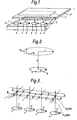
- Figure 1 illustrates schematically a first example of the invention;
- Figure 2 illustrates a single arc of a coil and the definitions of various algebraic values;
- Figure 3 illustrates the variation in magnetic field in the homogeneous zone due to part of the assembly shown in Figure 1;
- Figure 4A illustrates a second example of the invention;
- Figure. 4B illustrates a former for mounting the coils of the Figure 4A example;
- Figure 5 illustrates a third example of the invention; and,
- Figure 6 is a block diagram of NMR imaging apparatus.
- The examples described are all constituted by coils which typically are made of superconducting material and are thus positioned within a conventional liquid helium/nitrogen cryostat for cooling the coils to low temperatures. Such cryostats are well known and will not be further described or illustrated.
- The example shown in Figure 1 comprises eight coils 1-4,1'-4' arranged side by side in a two dimensional array and mounted on respective formers (not shown). As just mentioned, the coils 1-4,1'-4' are positioned in a cryostat schematically indicated by
reference numeral 5. It should be noted that an end turn of each coil 1-4 is positioned in a common plane 6. - In use, the coils 1-4,1'-4' are connected to a power supply for continuously supplying working currents to the coils. The currents flow through the coils in the same sense so that for example all the coils have North poles in the plane 6. The coils generate individual, usually different, magnetic fields which in a homogeneous region 7 combine to produce a substantially uniform magnetic field having a planar form and spaced from the plane 6.
- The uniformity of the magnetic field in the homogeneous region 7 depends upon the number of amp turns of each coil 1-4 and on the spacing between the coils. One way in which these variables may be determined will now be described.
- Since we are concerned with field values at points distributed widely in space and remote from the field coils we can calculate the field at each point directly. Figure 2 illustrates schematically a coil 8 having NI amp turns and a radius a. It is possible to determine the field components Hand H by employing elliptic integrals.
- The field component in the z direction Hz (z,r) is given by:

- The field component in the r direction Hr (z,r) is given by:


- To achieve field uniformity along a line in the projection plane 7 a simple optimisation routine can be used on a set of linear equations with current as the free variable. See Table 1.

- This matrix may be resolved by pivotal condensation, as an example, to yield the values of I1. I 2' I 3' I4 where the I values are the multiplying factors of the originally chosen amp turns in each coil.
- Using standard computing techniques a large number of field points may be chosen corresponding to a large number of coils.
- Table 2 below gives an example using the four coils 1-4, each of 400 mm diameter and with an axial spacing of 600 mm which project a homogeneous line 600 mm above their common radial plane 6. In this example the field oscillation is about 6% of the projected field.
- Each coil is an elemental arc with 10,000 Amp turns; field values are in gauss. It is practicable to increase all field values by a factor of at least 200, if each coil physically comprised about 6700 turns of conductor operating at 300 Amps.
- The total length of conductor is about 33 km making this system a similar cost in superconductor terms per unit field in the homogenous zone as a standard solenoidal magnet.

- In Table 1, the choice of values for the total field at each point (in the example Sl - S4) may be made either so the field has substantially the same value for each point S (as just described) or an impressed gradient may be set by some unique choice of values for each field point. For example, a first order gradient could be obtained for equidistance field points by nominating a set thus S1 = 1.111*S2 = 1.250*S. = 1.429*S4.
- When a grid of points is chosen in three dimensions, a gradient in any direction may be defined using the sum of the coil fields at each point. The optimisation procedure will set out currents in the coils for each of the chosen sets of S values; if the coils were driven by separate power supplies it would, therefore, be easy to create gradients of exactly the required strength in any direction for imaging.
- Figure 3 illustrates the variation of the magnetic field in the homogeneous region in a direction perpendicular to the alignment direction of the coils. The field values given in table 2 above correspond to the field along the line A-A in Figure 3. If the field is plotted along a second line B-B parallel to the line A-A, the field intensity will be less. Given a particular level of field variation peak to peak, the amount of sideways displacement of B-B may be defined. In this specific example, using only four coils 1-4 of equal amp turns, a 10% peak to peak oscillation permits 50 mm displacement either side of the optimisation line A-A. This effectively defines the plane of homogeneity. This homogeneous plane extends over three-quarters (approximately) of the length of the line joining the points of origin of the coils. Clearly the aspect ratio of length to width lends itself to sagittal imaging of patients in NMR imaging apparatus. For a fixed array of coils, the homogeneous region 7 may be moved closer to or further from the plane 6 of the coils 1-4 by varying the number of amp turns. In practice, the homogeneous region will have a small but finite thickness of about 10 mm.
- If the magnet assembly is to be used in NMR imaging apparatus, a non-magnetic planar support 7' will be positioned just below the homogeneous region 7 above the plane 6. A patient may then lie on the support so that his body intersects the homogeneous region 7. One of the major advantages of this is that the narrowness of the homogeneous region 7 means that in NMR imaging it may not be necessary to use magnetic gradients to define a plane in the patient's body. This may simply be done by suitably positioning the support, relatively to the homogeneous region. Alternatively, the support may be fixed relative to the plane 6 and the current through the coils 1-4 may be altered to move the homogeneous region.
- The homogeneous region may be provided with greater thickness by using more coils in the optimisation process and choosing field points on a cubic grid. This is illustrated in Figure 4A where each coil 1-4 has been replaced by three
subsidiary coils coil 9 is positioned in a common plane as before. This arrangement of coils produces a cuboidhomogeneous region 12. - The requirement for different numbers of turns in the coils 9-11 can easily be achieved using a sectioned former 13 (Figure 4B) Because of the large degree of projection achieved, the coils may be given a substantial length in their axial direction so achieving in effect a large number elemental arcs on relatively few physical supports. This makes possible a three dimensional imaging zone.
- It is possible to provide improved uniformity in a homogeneous plane parallel to the surface of the magnetic assembly by changing the coil geometry from circular to semi-rectangular as illustrated by the four coils 14-17 (Figure 5). Since the sides of the coils 14-17 normal to the line A-A are straight, the homogeneous line A-A (Figure 3) is automatically maintained when the line is displaced sideways in the plane to B-B. The homogeneous region 7 may be increased in depth, in the same way as in the Figure 4A example of circular arcs, by increasing the number of amp turns at different levels below the top of the magnet assembly, for example by providing additional semi-rectangular coils 18-21.
- Due to the straight conducting sides of the coils 14-21, all the optimisation points from a given coil array may be chosen on the line A-A. This means a smaller variation in field along A-A occurs for a given number of coils than for circular arcs when, to attain two-dimensional uniformity, field points of optimisation need to lie on the line B-B as well as on A-A.
- Figure 6 illustrates in block diagram form NMR imaging apparatus which is of conventional form except for the magnet assembly which may be as described in any of the examples above. The apparatus comprises a
magnet assembly 31 incorporating a power supply (not shown). The cryostat 6 is controlled by acryogenic control system 40 of a conventional type. - Current through the coils 1-4 is controlled by a
power drive 41 controlled fromcontrol logic 42. This enables either gradient fields to be set up in the region 7 or a thin enough uniform field to define a plane in the patient's body. Coils (not shown) for generating and receiving RF energy are also mounted on the magnet assembly, the RF transmitter being connected to anamplifier 44 which is connected to aspectrometer 45. The RF receiver which detects the NMR signal is also connected to thespectrometer 45. The generation of RF pulses is controlled by thecontrol logic 42 which is connected to thespectrometer 45. NMR data from thespectrometer 45 passes to adata acquisition system 46 which is controlled by thecontrol logic 42. Data from thesystem 46 then passes toprocessing logic logic 47. - The overall control of the system is provided by a
computer 48 which is connected via a conventional RS 232 interface to anoperator input station 49. Information for the computer is stored in adisc drive 50 while the results of the imaging experiments are passed by the computer to adisplay system 51 which can display "slices" through the patient's body on a monitor 52.
Claims (10)
Applications Claiming Priority (2)
| Application Number | Priority Date | Filing Date | Title |
|---|---|---|---|
| GB848432439A GB8432439D0 (en) | 1984-12-21 | 1984-12-21 | Magnet assembly |
| GB8432439 | 1984-12-21 |
Publications (2)
| Publication Number | Publication Date |
|---|---|
| EP0186998A1 true EP0186998A1 (en) | 1986-07-09 |
| EP0186998B1 EP0186998B1 (en) | 1989-11-02 |
Family
ID=10571619
Family Applications (1)
| Application Number | Title | Priority Date | Filing Date |
|---|---|---|---|
| EP85309066A Expired EP0186998B1 (en) | 1984-12-21 | 1985-12-12 | Magnet assembly |
Country Status (5)
| Country | Link |
|---|---|
| US (1) | US4985679A (en) |
| EP (1) | EP0186998B1 (en) |
| JP (1) | JPS61160907A (en) |
| DE (1) | DE3574053D1 (en) |
| GB (1) | GB8432439D0 (en) |
Cited By (7)
| Publication number | Priority date | Publication date | Assignee | Title |
|---|---|---|---|---|
| GB2202333A (en) * | 1987-03-19 | 1988-09-21 | Oreal | A device for creating a magnetic field gradient for the examination of a body by nuclear magnetic resonance |
| WO1990004258A1 (en) * | 1988-10-14 | 1990-04-19 | Oxford Advanced Technology Limited | Magnetic field generating assembly and method |
| EP0400922A1 (en) * | 1989-06-01 | 1990-12-05 | Oxford Medical Limited | Magnetic field generating apparatus |
| WO1991012538A1 (en) * | 1990-02-08 | 1991-08-22 | Oxford Instruments Limited | Magnetic field generating assembly |
| EP0774670A1 (en) * | 1995-11-16 | 1997-05-21 | Siemens Aktiengesellschaft | Magnet assembly for a diagnostic magnetic resonance apparatus |
| FR2754066A1 (en) * | 1996-10-01 | 1998-04-03 | Oreal | DEVICE FOR EXAMINING LOW DEPTH VOLUME BY NUCLEAR MAGNETIC RESONANCE |
| WO2009111165A1 (en) * | 2008-02-18 | 2009-09-11 | Advanced Magnet Lab, Inc. | Helical coil design and process for direct fabrication from a conductive layer |
Families Citing this family (15)
| Publication number | Priority date | Publication date | Assignee | Title |
|---|---|---|---|---|
| JPH03236829A (en) * | 1990-02-14 | 1991-10-22 | Toshiba Corp | Magnetic resonance imaging device |
| US5160888A (en) * | 1991-04-29 | 1992-11-03 | Bruker Instruments, Inc. | Method and apparatus for one sided magnetic resonance imaging |
| GB9113223D0 (en) * | 1991-06-19 | 1991-08-07 | Oxford Instr Ltd | Energy storage device |
| US5633588A (en) * | 1994-09-16 | 1997-05-27 | Hitachi Medical Corporation | Superconducting magnet apparatus using superconducting multilayer composite member, method of magnetizing the same and magnetic resonance imaging system employing the same |
| GB9701094D0 (en) * | 1997-01-20 | 1997-03-12 | Oxford Instr Uk Ltd | Magnet assembly |
| DE29805903U1 (en) | 1998-03-31 | 1998-06-10 | Siemens Ag | Magnet for nuclear magnetic resonance devices |
| US6208142B1 (en) | 1998-12-07 | 2001-03-27 | Transurgical, Inc. | Magnetic resonance apparatus and methods with shim adjustment |
| US6278351B1 (en) * | 1999-01-11 | 2001-08-21 | Transurgical, Inc. | Multi-coil MRI magnet |
| US7422654B2 (en) * | 2003-02-14 | 2008-09-09 | Applied Materials, Inc. | Method and apparatus for shaping a magnetic field in a magnetic field-enhanced plasma reactor |
| FR2859791B1 (en) * | 2003-09-15 | 2007-06-08 | Commissariat Energie Atomique | NMR MACHINE WITH PERFECTED GRADIENT COILS |
| GB0414431D0 (en) * | 2004-06-28 | 2004-07-28 | Oxford Instr Plc | Magnetic resonance apparatus |
| GB0426957D0 (en) * | 2004-12-08 | 2005-01-12 | Univ Surrey | Apparatus and method for nuclear magnetic resonance |
| GB0508890D0 (en) * | 2005-04-29 | 2005-06-08 | Oxford Instr Plc | Magnetic resonance apparatus and method |
| WO2013023186A1 (en) * | 2011-08-10 | 2013-02-14 | Kharbanda Hardave S | System and method for the establishment of magnetic field patterns in a coil set with voltage-driven current shunts |
| KR20200118893A (en) * | 2013-02-14 | 2020-10-16 | 제이.에스.파스리챠 엔터프라이지스, 엘엘씨 | Magnetic resonance imaging with a single thick loop |
Citations (5)
| Publication number | Priority date | Publication date | Assignee | Title |
|---|---|---|---|---|
| US3783794A (en) * | 1971-07-28 | 1974-01-08 | Krauss Maffei Ag | Magnetic suspension system for vehicles and the like with non controlled suspending magnets |
| DE2436466A1 (en) * | 1974-07-29 | 1976-02-12 | Weh Herbert | Switching points for levitated railway system - uses asynchronous stator elements for short period power supply |
| DE2822953A1 (en) * | 1977-05-27 | 1978-11-30 | Nat Res Dev | METHOD OF EXAMINATION OF SAMPLE |
| US4361822A (en) * | 1981-08-18 | 1982-11-30 | Adler David T | Magnetic pallet |
| EP0108421A2 (en) * | 1982-11-08 | 1984-05-16 | Kabushiki Kaisha Toshiba | Nuclear magnetic resonance diagnostic apparatus |
Family Cites Families (14)
| Publication number | Priority date | Publication date | Assignee | Title |
|---|---|---|---|---|
| US3199021A (en) * | 1960-12-19 | 1965-08-03 | Varian Associates | Apparatus for improving the homogeneity of a magnetic field |
| US3296569A (en) * | 1962-08-27 | 1967-01-03 | Japan Atomic Energy Res Inst | Magnet assembly capable of controlling distribution of magnetic field |
| US3287630A (en) * | 1964-03-02 | 1966-11-22 | Varian Associates | Apparatus for improving the uniformity of magnetic fields |
| US3488561A (en) * | 1965-03-23 | 1970-01-06 | Varian Associates | Apparatus for controlling magnetic fields |
| US3470828A (en) * | 1967-11-21 | 1969-10-07 | James R Powell Jr | Electromagnetic inductive suspension and stabilization system for a ground vehicle |
| US3564398A (en) * | 1969-07-18 | 1971-02-16 | Varian Associates | Magnetic field homogenizing coil sets having spatial independence and spectrometer means using same |
| SU518712A1 (en) * | 1974-07-08 | 1976-06-25 | Ленинградский Ордена Ленина И Ордена Трудового Красного Знамени Государственный Университет Им.А.А.Жданова | The method of obtaining kinematic spin echo signals in an external inhomogeneous magnetic field |
| US4374360A (en) * | 1980-05-29 | 1983-02-15 | Sepponen Raimo E | NMR Diagnosis apparatus |
| JPS5940843A (en) * | 1982-08-31 | 1984-03-06 | 株式会社東芝 | Nuclear magnetic resonance apparatus for diagnosis |
| US4673882A (en) * | 1984-03-06 | 1987-06-16 | Buford J Philip | Magnetic system for nuclear magnetic resonance diagnostic device |
| JPS60210804A (en) * | 1984-04-04 | 1985-10-23 | Hitachi Ltd | Permanent magnet apparatus |
| US4721914A (en) * | 1984-05-01 | 1988-01-26 | The United States Of America As Represented By The United States Department Of Energy | Apparatus for unilateral generation of a homogeneous magnetic field |
| GB8500248D0 (en) * | 1985-01-04 | 1985-02-13 | Oxford Magnet Tech | Solenoids |
| US4682111A (en) * | 1985-03-05 | 1987-07-21 | Kabushiki Kaisha Toshiba | Magnetic resonance imaging magnet |
-
1984
- 1984-12-21 GB GB848432439A patent/GB8432439D0/en active Pending
-
1985
- 1985-12-12 EP EP85309066A patent/EP0186998B1/en not_active Expired
- 1985-12-12 DE DE8585309066T patent/DE3574053D1/en not_active Expired
- 1985-12-20 JP JP60289115A patent/JPS61160907A/en active Granted
-
1989
- 1989-09-29 US US07/445,113 patent/US4985679A/en not_active Expired - Lifetime
Patent Citations (5)
| Publication number | Priority date | Publication date | Assignee | Title |
|---|---|---|---|---|
| US3783794A (en) * | 1971-07-28 | 1974-01-08 | Krauss Maffei Ag | Magnetic suspension system for vehicles and the like with non controlled suspending magnets |
| DE2436466A1 (en) * | 1974-07-29 | 1976-02-12 | Weh Herbert | Switching points for levitated railway system - uses asynchronous stator elements for short period power supply |
| DE2822953A1 (en) * | 1977-05-27 | 1978-11-30 | Nat Res Dev | METHOD OF EXAMINATION OF SAMPLE |
| US4361822A (en) * | 1981-08-18 | 1982-11-30 | Adler David T | Magnetic pallet |
| EP0108421A2 (en) * | 1982-11-08 | 1984-05-16 | Kabushiki Kaisha Toshiba | Nuclear magnetic resonance diagnostic apparatus |
Non-Patent Citations (1)
| Title |
|---|
| REVIEW OF SCIENTIFIC INSTRUMENT, vol. 52, no. 10, October 1981, pages 1501-1508, American Institute of Physics, New York, US; H. SAINT-JALMES et al.: "Optimization of homogeneous electromagnetic coil systems: Application to whole-body NMR imaging magnets" * |
Cited By (16)
| Publication number | Priority date | Publication date | Assignee | Title |
|---|---|---|---|---|
| GB2202333A (en) * | 1987-03-19 | 1988-09-21 | Oreal | A device for creating a magnetic field gradient for the examination of a body by nuclear magnetic resonance |
| US4870363A (en) * | 1987-03-19 | 1989-09-26 | L'oreal | Apparatus for creating a magnetic field gradient and the examination of a surface layer of a body |
| GB2202333B (en) * | 1987-03-19 | 1990-04-18 | Oreal | Method and apparatus for the examination of a body by nuclear magnetic resonance by slow and fast methods, and a device for creating a magnetic field gradient |
| WO1990004258A1 (en) * | 1988-10-14 | 1990-04-19 | Oxford Advanced Technology Limited | Magnetic field generating assembly and method |
| EP0400922A1 (en) * | 1989-06-01 | 1990-12-05 | Oxford Medical Limited | Magnetic field generating apparatus |
| US5084677A (en) * | 1989-06-01 | 1992-01-28 | Oxford Medical Limited | Magnetic field generating apparatus |
| WO1991012538A1 (en) * | 1990-02-08 | 1991-08-22 | Oxford Instruments Limited | Magnetic field generating assembly |
| US5331282A (en) * | 1990-02-08 | 1994-07-19 | Oxford Instruments (Uk) Limited | Magnetic field generating assembly |
| EP0774670A1 (en) * | 1995-11-16 | 1997-05-21 | Siemens Aktiengesellschaft | Magnet assembly for a diagnostic magnetic resonance apparatus |
| US5708362A (en) * | 1995-11-16 | 1998-01-13 | Siemens Aktiengesellschaft | Magnet arrangement for a diagnostic magnetic resonance apparatus |
| FR2754066A1 (en) * | 1996-10-01 | 1998-04-03 | Oreal | DEVICE FOR EXAMINING LOW DEPTH VOLUME BY NUCLEAR MAGNETIC RESONANCE |
| EP0834747A2 (en) * | 1996-10-01 | 1998-04-08 | L'oreal | Device for examination by nuclear magnetic resonance of a volume of slight depth |
| EP0834747A3 (en) * | 1996-10-01 | 2000-03-29 | L'oreal | Device for examination by nuclear magnetic resonance of a volume of slight depth |
| US6091241A (en) * | 1996-10-01 | 2000-07-18 | L'oreal | Device for examining a volume of small depth by nuclear magnetic resonance |
| WO2009111165A1 (en) * | 2008-02-18 | 2009-09-11 | Advanced Magnet Lab, Inc. | Helical coil design and process for direct fabrication from a conductive layer |
| US7889042B2 (en) | 2008-02-18 | 2011-02-15 | Advanced Magnet Lab, Inc. | Helical coil design and process for direct fabrication from a conductive layer |
Also Published As
| Publication number | Publication date |
|---|---|
| DE3574053D1 (en) | 1989-12-07 |
| GB8432439D0 (en) | 1985-02-06 |
| JPH0584647B2 (en) | 1993-12-02 |
| JPS61160907A (en) | 1986-07-21 |
| EP0186998B1 (en) | 1989-11-02 |
| US4985679A (en) | 1991-01-15 |
Similar Documents
| Publication | Publication Date | Title |
|---|---|---|
| EP0186998B1 (en) | Magnet assembly | |
| EP0187691B1 (en) | Improvements relating to magnets | |
| US4587504A (en) | Magnet assembly for use in NMR apparatus | |
| EP0160350B1 (en) | Magnet assembly | |
| US6411187B1 (en) | Adjustable hybrid magnetic apparatus | |
| Kirschvink | Uniform magnetic fields and double‐wrapped coil systems: Improved techniques for the design of bioelectromagnetic experiments | |
| US5315276A (en) | Compact superconducting magnet for magnetic resonance imaging | |
| EP0404461B1 (en) | Gradient coil assemblies for generating magnetic field gradients across a region | |
| US4733189A (en) | Magnetic resonance imaging systems | |
| EP0371775B1 (en) | Permanent magnet arrangement | |
| WO2011066652A1 (en) | Method and apparatus for producing homogeneous magnetic fields | |
| US5177441A (en) | Elliptical cross section gradient oil | |
| US6262576B1 (en) | Phased array planar gradient coil set for MRI systems | |
| EP0819948B1 (en) | Superconducting MR yoke magnet and method of energizing same | |
| US4658229A (en) | Magnet system providing a region of substantially homogeneous field strength | |
| EP0400922A1 (en) | Magnetic field generating apparatus | |
| US4755755A (en) | Compact transverse magnetic gradient coils and dimensioning method therefor | |
| US5977771A (en) | Single gradient coil configuration for MRI systems with orthogonal directed magnetic fields | |
| USRE36782E (en) | Magnet assembly for use in NMR apparatus | |
| EP0407384B1 (en) | Magnet assembly | |
| Lugansky | Optimal coils for producing uniform magnetic fields | |
| Frenkiel et al. | Apparatus for generation of magnetic field gradient waveforms for NMR imaging | |
| JP2004275770A (en) | Mri with pulsed readout magnet | |
| Takada et al. | Application of fibre-optic magnetic-field sensor to kicker magnet | |
| Van der Heide et al. | The Eindhoven minicyclotron project ILEC |
Legal Events
| Date | Code | Title | Description |
|---|---|---|---|
| PUAI | Public reference made under article 153(3) epc to a published international application that has entered the european phase |
Free format text: ORIGINAL CODE: 0009012 |
|
| AK | Designated contracting states |
Kind code of ref document: A1 Designated state(s): DE FR GB IT NL |
|
| RAP1 | Party data changed (applicant data changed or rights of an application transferred) |
Owner name: OXFORD MAGNET TECHNOLOGY LIMITED |
|
| 17P | Request for examination filed |
Effective date: 19861029 |
|
| 17Q | First examination report despatched |
Effective date: 19880427 |
|
| GRAA | (expected) grant |
Free format text: ORIGINAL CODE: 0009210 |
|
| AK | Designated contracting states |
Kind code of ref document: B1 Designated state(s): DE FR GB IT NL |
|
| RAP2 | Party data changed (patent owner data changed or rights of a patent transferred) |
Owner name: OXFORD ADVANCED TECHNOLOGY LIMITED |
|
| ET | Fr: translation filed | ||
| REF | Corresponds to: |
Ref document number: 3574053 Country of ref document: DE Date of ref document: 19891207 |
|
| ITF | It: translation for a ep patent filed |
Owner name: JACOBACCI & PERANI S.P.A. |
|
| PLBE | No opposition filed within time limit |
Free format text: ORIGINAL CODE: 0009261 |
|
| STAA | Information on the status of an ep patent application or granted ep patent |
Free format text: STATUS: NO OPPOSITION FILED WITHIN TIME LIMIT |
|
| 26N | No opposition filed | ||
| REG | Reference to a national code |
Ref country code: FR Ref legal event code: ST |
|
| ITTA | It: last paid annual fee | ||
| REG | Reference to a national code |
Ref country code: FR Ref legal event code: RC |
|
| REG | Reference to a national code |
Ref country code: FR Ref legal event code: DA |
|
| REG | Reference to a national code |
Ref country code: GB Ref legal event code: IF02 |
|
| PGFP | Annual fee paid to national office [announced via postgrant information from national office to epo] |
Ref country code: NL Payment date: 20041205 Year of fee payment: 20 |
|
| PGFP | Annual fee paid to national office [announced via postgrant information from national office to epo] |
Ref country code: GB Payment date: 20041208 Year of fee payment: 20 Ref country code: FR Payment date: 20041208 Year of fee payment: 20 |
|
| PGFP | Annual fee paid to national office [announced via postgrant information from national office to epo] |
Ref country code: DE Payment date: 20041209 Year of fee payment: 20 |
|
| REG | Reference to a national code |
Ref country code: GB Ref legal event code: 732E |
|
| NLS | Nl: assignments of ep-patents |
Owner name: OXFORD INSTRUMENTS SUPERCONDUCTIVITY LIMITED |
|
| NLT1 | Nl: modifications of names registered in virtue of documents presented to the patent office pursuant to art. 16 a, paragraph 1 |
Owner name: OXFORD INSTRUMENTS MEDICAL LIMITED Owner name: OXFORD INSTRUMENTS MEDICAL SYSTEMS LIMITED Owner name: OXFORD MEDICAL LIMITED |
|
| REG | Reference to a national code |
Ref country code: FR Ref legal event code: CD Ref country code: FR Ref legal event code: TQ Ref country code: FR Ref legal event code: CA |
|
| PG25 | Lapsed in a contracting state [announced via postgrant information from national office to epo] |
Ref country code: GB Free format text: LAPSE BECAUSE OF EXPIRATION OF PROTECTION Effective date: 20051211 |
|
| PG25 | Lapsed in a contracting state [announced via postgrant information from national office to epo] |
Ref country code: NL Free format text: LAPSE BECAUSE OF EXPIRATION OF PROTECTION Effective date: 20051212 |
|
| REG | Reference to a national code |
Ref country code: GB Ref legal event code: PE20 |
|
| NLV7 | Nl: ceased due to reaching the maximum lifetime of a patent |
Effective date: 20051212 |