EP0186941A1 - Matrix interconnected local area networks - Google Patents
Matrix interconnected local area networks Download PDFInfo
- Publication number
- EP0186941A1 EP0186941A1 EP85307278A EP85307278A EP0186941A1 EP 0186941 A1 EP0186941 A1 EP 0186941A1 EP 85307278 A EP85307278 A EP 85307278A EP 85307278 A EP85307278 A EP 85307278A EP 0186941 A1 EP0186941 A1 EP 0186941A1
- Authority
- EP
- European Patent Office
- Prior art keywords
- local area
- lan
- matrix
- call sign
- area networks
- Prior art date
- Legal status (The legal status is an assumption and is not a legal conclusion. Google has not performed a legal analysis and makes no representation as to the accuracy of the status listed.)
- Ceased
Links
Images


Classifications
-
- H—ELECTRICITY
- H04—ELECTRIC COMMUNICATION TECHNIQUE
- H04L—TRANSMISSION OF DIGITAL INFORMATION, e.g. TELEGRAPHIC COMMUNICATION
- H04L12/00—Data switching networks
-
- H—ELECTRICITY
- H04—ELECTRIC COMMUNICATION TECHNIQUE
- H04L—TRANSMISSION OF DIGITAL INFORMATION, e.g. TELEGRAPHIC COMMUNICATION
- H04L12/00—Data switching networks
- H04L12/28—Data switching networks characterised by path configuration, e.g. LAN [Local Area Networks] or WAN [Wide Area Networks]
- H04L12/46—Interconnection of networks
Definitions
- the present invention relates to a system of matrix interconnected local area networks for the transmission of information between user terminals and equipment, e.g. databases, and access stations to other networks.
- a switching matrix provides a switched interface for linking together a number of local area networks, each network being provided with transmit and receive buses to which all its user terminals are connected, the buses further being connected to the switching matrix in a manner that enables the transmit and receive buses of different networks to be connected together in a particular sequence; each local area network is further provided with a master station for applying a unique call sign on its transmit bus to the switching matrix, and for monitoring its receive bus to detect the call sign of the local area network to which it is currently connected via the switching matrix, so that when a master station of a local area network detects a call sign of a different network it stops transmitting its call sign to allow the different network and the detecting network to communicate with each other.
- Each network is interconnected to a switching matrix SM by way of a transmit bus TBA and a receive bus RBA, for example.
- the buses may conveniently be optical fibre links or wires.
- Each local area network is provided with connections, such as C1-C3 for the connection of user terminals and other equipment to the system. All the user terminals are connected to the local area network by way of isolation circuits, to reduce the effect of faults on the system.
- the switching matrix SM takes the form of an optical matrix where optical fibre links are used for buses TB, RB, or the form of an electronic switching matrix where wires are used for the buses. With suitable conversion either switch type can be used with either transmission medium.
- the switching matrix comprises a number of switch cross-points but may be realised in any known configuration, e.g. a lattice arrangement as is currently used for optical switches.
- the switches are driven so as to connect each pair of transmit and receive buses TBA, RBA, for example, with another pair of buses, RBC, TBC for example.
- the switching matrix is shown in Figure 2, and in the present embodiment four pairs of buses are connected at a time, and the connection sequence is shown in Table 1. Therefore, there are four pairs of buses each carrying the local network bit rate.
- the timing of the sequence of Table 1 can be determined internally to the switching matrix SM by a pre-set sequential wave form generator driving the switches, and if required, the timing of the connection of four pairs can be made different to suit traffic predictions.
- the switching matrix can monitor the traffic flowing from each local area network and influence switching periods by the traffic pattern, within certain limits.
- each interconnection is made by metal oxide silicon (MOS) transistor having a controlling gate G, and connections D and S connected to respective local area network outputs and inputs.
- the control signals 1-4 are shown, and in Figure 3, the control signals 1 and 2 are presented to the controlling gates of the transistors to permit the output W of local area network LAN A to be switched to the input of local area network LAN B; and the output X of local area network LAN B to be switched to the input of local area network LAN A.
- MOS metal oxide silicon
- control signal 1 is at 0 volts, while control signal 2 is positive.
- the control signals may be free running or may be derived from the system and clocked if synchronism is required.
- Each local area network is provided with a master station which applies a unique call sign on its transmit bus traffic periods. All stations monitor their receive bus to detect the call sign of the local area network to which they are currently connected by way of the switching matrix.
- the transmit and receive signals for local area network LAN A are shown by way of an example.
- the local area network master station of LAN A detects call sign B, after a guard period it stops its call sign and allows the system to transmit traffic intended for local area network LAN B and vice versa.
- the master station for local area network LAN A starts to send its call sign again thus inhibiting further traffic, ready for switching to a different local area network, for example, LAN C.
- LAN C for example, LAN C.
- the local area networks can be of known types, suitably modified for this method of networking and can carry a mixture of voice, data and video.
- the working bit rates of local area networks are constantly being improved, and with four networks as described, a total traffic working bit rate approaching four times the rate of a single network can be achieved in a wide area network.
- the local area networks could take the form of a telecommunication exchange, such as a private automatic branch exchange PABX, suitably modified, where the PABX local highways are sequentially linked by way of the matrix switch.
- a telecommunication exchange such as a private automatic branch exchange PABX, suitably modified, where the PABX local highways are sequentially linked by way of the matrix switch.
Abstract
0 The matrix is for use in providing a switched interface for linking together a number of local area networks (LAN's) of differing types. Each LAN has a transmit and receive bus to which all its stations are connected either directly by wire or via an optic fibre to a matrix switch which can either be an optical or an electronic switch. The switch cross-points are driven so as to connect each pair of transmit and receive busses together in sequence. The sequence can be determined within the matrix switch and can involve differing time periods to suit traffic predictions. Alternatively the switch may be arranged to monitor the traffic flow from each LAN and be able to influence switching periods accordingly. Each LAN has a master station which applies a unique call sign on its transmit highway to the switch between traffic periods and monitors its receive highway to detect the call sign of the LAN to which it is currently connected via the switch. When for example LANA detects call sign B, after a guard period it stops its call sign and allows the LAN system to transmit traffic intended for LANB and vice versa. After a fixed period of time based upon the predetermined switch timing LANA master station starts to send its call sign again ready for switching to a different LAN.
Description
- The present invention relates to a system of matrix interconnected local area networks for the transmission of information between user terminals and equipment, e.g. databases, and access stations to other networks.
- Hitherto, systems of local area networks have been based on a common highway or bus to which user stations are connected in a parallel, or on a ring configuration in which tandem nodes have user stations connected to them. The total bit rate available to the users is limited by the operational bit rate of the common bus or ring.
- There are various ways known in the prior art of linking together a system comprising a number of local area networks. This is accomplished for example, by having stations or nodes common to two buses or rings, or by, using a number of buses or rings in parallel. However, they suffer from limited flexibility and do not always provide the combined total bit rate of the local area networks in the system.
- Accordingly, it is an object of the present invention to provide a system of interconnected local area networks which have an improved total bit rate and improved flexibility over known systems.
- It is a further object of the invention to provide a system of interconnected local area networks which can handle a wider range of traffic types with improved reliability over known systems.
- According to the present invention there is provided a system of matrix interconnected local area networks, wherein a switching matrix provides a switched interface for linking together a number of local area networks, each network being provided with transmit and receive buses to which all its user terminals are connected, the buses further being connected to the switching matrix in a manner that enables the transmit and receive buses of different networks to be connected together in a particular sequence; each local area network is further provided with a master station for applying a unique call sign on its transmit bus to the switching matrix, and for monitoring its receive bus to detect the call sign of the local area network to which it is currently connected via the switching matrix, so that when a master station of a local area network detects a call sign of a different network it stops transmitting its call sign to allow the different network and the detecting network to communicate with each other.
- An embodiment of the present invention will now be described with reference to the accompanying drawings in which:
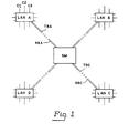
- Figure 1 shows a system comprising a number of local area networks connected to a switching matrix,
- Figure 2 shows the switching matrix interconnections for the local area networks, together with Table 1 showing a typical cross-point connection sequence,
- Figure 3 shows part of the switching matrix interconnections shown in Figure 2, together with an example of switching transistors at the interconnections; and the control signals.
- Figure 4a shows a transmit signal for a local area network LAN A; and,
- Figure 4b shows a receive signal for the local area network LAN A.
- Referring to Figure 1, four local area networks LAN A, LAN B, LAN C and LAN D are shown. Each network is interconnected to a switching matrix SM by way of a transmit bus TBA and a receive bus RBA, for example. The buses may conveniently be optical fibre links or wires. Each local area network is provided with connections, such as C1-C3 for the connection of user terminals and other equipment to the system. All the user terminals are connected to the local area network by way of isolation circuits, to reduce the effect of faults on the system.
- The switching matrix SM takes the form of an optical matrix where optical fibre links are used for buses TB, RB, or the form of an electronic switching matrix where wires are used for the buses. With suitable conversion either switch type can be used with either transmission medium.
- The switching matrix comprises a number of switch cross-points but may be realised in any known configuration, e.g. a lattice arrangement as is currently used for optical switches. The switches are driven so as to connect each pair of transmit and receive buses TBA, RBA, for example, with another pair of buses, RBC, TBC for example. The switching matrix is shown in Figure 2, and in the present embodiment four pairs of buses are connected at a time, and the connection sequence is shown in Table 1. Therefore, there are four pairs of buses each carrying the local network bit rate.
- The timing of the sequence of Table 1 can be determined internally to the switching matrix SM by a pre-set sequential wave form generator driving the switches, and if required, the timing of the connection of four pairs can be made different to suit traffic predictions. Alternatively, the switching matrix can monitor the traffic flowing from each local area network and influence switching periods by the traffic pattern, within certain limits.
- Referring to Figure 3, each interconnection is made by metal oxide silicon (MOS) transistor having a controlling gate G, and connections D and S connected to respective local area network outputs and inputs. The control signals 1-4 are shown, and in Figure 3, the
control signals - To achieve the above switching conditions,
control signal 1 is at 0 volts, whilecontrol signal 2 is positive. The control signals may be free running or may be derived from the system and clocked if synchronism is required. - Each local area network is provided with a master station which applies a unique call sign on its transmit bus traffic periods. All stations monitor their receive bus to detect the call sign of the local area network to which they are currently connected by way of the switching matrix.
- Referring to Figures 4a and 4b, the transmit and receive signals for local area network LAN A are shown by way of an example. When the local area network master station of LAN A detects call sign B, after a guard period it stops its call sign and allows the system to transmit traffic intended for local area network LAN B and vice versa. After a fixed period of time based on the predetermined switching matrix timing, the master station for local area network LAN A starts to send its call sign again thus inhibiting further traffic, ready for switching to a different local area network, for example, LAN C. If preferred LAN A when transmitting to LAN B can for example receive from LAN C rather than LAN B.
- The local area networks can be of known types, suitably modified for this method of networking and can carry a mixture of voice, data and video. The working bit rates of local area networks are constantly being improved, and with four networks as described, a total traffic working bit rate approaching four times the rate of a single network can be achieved in a wide area network.
- Furthermore, the local area networks could take the form of a telecommunication exchange, such as a private automatic branch exchange PABX, suitably modified, where the PABX local highways are sequentially linked by way of the matrix switch.
Claims (5)
1. A system of matrix interconnected local area networks, wherein a switching matrix provides a switched interface for linking together a number of local area networks, each network being provided with transmit and receive buses to which all its user terminals are connected, the buses further being connected to the switching matrix in a manner that enables the transmit and receive buses of different networks to be connected together in a particular sequence; each local area network is further provided with a master station for applying a unique call sign on its transmit bus to the switching matrix, and for monitoring its receive bus to detect the call sign of the local area network to which it is currently connected via the switching matrix, so that when a master station of a local area network detects a call sign of a different network it stops transmitting its call sign to allow the different network and the detecting network to communicate with each other.
2. A system of matrix interconnected local area networks as claimed in claim 1, wherein each master station, after a fixed period of time, re-transmits its call sign to inhibit further communication, ready for switching to a different local area network.
3. A system of matrix interconnected local area networks as claimed in claim 1 or 2, wherein the buses are wire buses, and the switching matrix comprises a plurality of switching transistors.
4. A system of matrix interconnected local area networks as claimed in claim 1 or 2 wherein the buses are optional fibre links, and the switching matrix comprises a plurality of optical switching devices.
5. A system of matrix interconnected local area networks as claimed in any preceding claim, wherein the local area networks are telecommunication exchanges.
Applications Claiming Priority (2)
| Application Number | Priority Date | Filing Date | Title |
|---|---|---|---|
| GB8427748 | 1984-11-02 | ||
| GB848427748A GB8427748D0 (en) | 1984-11-02 | 1984-11-02 | Matrix interconnected local area networks |
Publications (1)
| Publication Number | Publication Date |
|---|---|
| EP0186941A1 true EP0186941A1 (en) | 1986-07-09 |
Family
ID=10569149
Family Applications (1)
| Application Number | Title | Priority Date | Filing Date |
|---|---|---|---|
| EP85307278A Ceased EP0186941A1 (en) | 1984-11-02 | 1985-10-11 | Matrix interconnected local area networks |
Country Status (4)
| Country | Link |
|---|---|
| EP (1) | EP0186941A1 (en) |
| JP (1) | JPS61111039A (en) |
| FI (1) | FI854265L (en) |
| GB (2) | GB8427748D0 (en) |
Families Citing this family (3)
| Publication number | Priority date | Publication date | Assignee | Title |
|---|---|---|---|---|
| GB2187367B (en) * | 1986-01-09 | 1990-03-28 | Ricoh Kk | Control system for local area network |
| US5043975A (en) * | 1989-06-29 | 1991-08-27 | Digital Equipment Corporation | High bandwidth network based on wavelength division multiplexing |
| JPH07158321A (en) * | 1993-12-06 | 1995-06-20 | Kazuyuki Myoga | Tent |
Citations (2)
| Publication number | Priority date | Publication date | Assignee | Title |
|---|---|---|---|---|
| WO1982003740A1 (en) * | 1981-04-16 | 1982-10-28 | Ncr Co | Data processing system employing broadcast packet switching |
| EP0067431A2 (en) * | 1981-06-12 | 1982-12-22 | Siemens Aktiengesellschaft | Network with a number of optical signal transmission lines interconnectable by optical mixers |
-
1984
- 1984-11-02 GB GB848427748A patent/GB8427748D0/en active Pending
-
1985
- 1985-08-01 GB GB08519371A patent/GB2166626B/en not_active Expired
- 1985-10-11 EP EP85307278A patent/EP0186941A1/en not_active Ceased
- 1985-10-30 FI FI854265A patent/FI854265L/en not_active IP Right Cessation
- 1985-11-01 JP JP24427785A patent/JPS61111039A/en active Granted
Patent Citations (2)
| Publication number | Priority date | Publication date | Assignee | Title |
|---|---|---|---|---|
| WO1982003740A1 (en) * | 1981-04-16 | 1982-10-28 | Ncr Co | Data processing system employing broadcast packet switching |
| EP0067431A2 (en) * | 1981-06-12 | 1982-12-22 | Siemens Aktiengesellschaft | Network with a number of optical signal transmission lines interconnectable by optical mixers |
Also Published As
| Publication number | Publication date |
|---|---|
| FI854265A0 (en) | 1985-10-30 |
| GB8519371D0 (en) | 1985-09-04 |
| FI854265L (en) | 1986-05-03 |
| GB8427748D0 (en) | 1984-12-12 |
| JPS61111039A (en) | 1986-05-29 |
| GB2166626B (en) | 1988-08-03 |
| GB2166626A (en) | 1986-05-08 |
| JPH0439251B2 (en) | 1992-06-29 |
Similar Documents
| Publication | Publication Date | Title |
|---|---|---|
| US4723272A (en) | Telecommunication system, in particular telephone system | |
| US5341232A (en) | Star-shaped network for data communication between stations | |
| JPS62189895A (en) | Method and apparatus for establishing wide band communication facility through communication network with narrow band channel | |
| EP0561490B1 (en) | Method for establishing wideband communications through a time division switching system | |
| EP0186941A1 (en) | Matrix interconnected local area networks | |
| KR860009564A (en) | Network connection system | |
| JPS6054556A (en) | Subscriber connection digital satellite station | |
| JPH0813014B2 (en) | Modular active optical fiber coupler unit and system thereof | |
| US3251945A (en) | Circuit arrangement constructed in the manner of a coupling multiple for the connection of time multiplex telephone systems | |
| CN85109293A (en) | The system of data, services is provided in the circuit switching exchange | |
| KR920010221B1 (en) | Line concentration system | |
| FI74860C (en) | KOPPLINGSFAELT MED FOERBINDELSEOMKASTNING, SAERSKILT FOER TELEFONCENTRALER. | |
| JPS61164361A (en) | Continuity test system | |
| JP2739070B2 (en) | Packet switching system | |
| JPS59123353A (en) | Communication path connecting system of centralized subscriber line test | |
| FI863251A0 (en) | KOPPLINGSANORDNING FOER FJAERRKOMMUNIKATIONSFOERMEDLINGSANLAEGGNINGAR, MED KOPPLINGSFAELT FOER EN- OCH FLERKANALFOERBINDELSER. | |
| JPS58164355A (en) | Switching system between leased circuit and switching circuit for information communication | |
| RU2119263C1 (en) | Digital switching system | |
| EP0243291A2 (en) | Improvements in a new simultaneous voice and data communication system, with possibility of connection to public or private networks | |
| JPS595796A (en) | Control and switching system for remote station | |
| JPS61192154A (en) | Composite conference system | |
| CN1009605B (en) | Information transmitting device | |
| JPS592475A (en) | System for controlling loss probability on type of call | |
| JPS60247392A (en) | Line distributing circuit | |
| CN1004323B (en) | Telecommunication system, in particular telephone system |
Legal Events
| Date | Code | Title | Description |
|---|---|---|---|
| PUAI | Public reference made under article 153(3) epc to a published international application that has entered the european phase |
Free format text: ORIGINAL CODE: 0009012 |
|
| AK | Designated contracting states |
Kind code of ref document: A1 Designated state(s): AT BE CH DE FR IT LI LU NL SE |
|
| 17P | Request for examination filed |
Effective date: 19870124 |
|
| 17Q | First examination report despatched |
Effective date: 19881027 |
|
| STAA | Information on the status of an ep patent application or granted ep patent |
Free format text: STATUS: THE APPLICATION HAS BEEN REFUSED |
|
| 18R | Application refused |
Effective date: 19900210 |
|
| RIN1 | Information on inventor provided before grant (corrected) |
Inventor name: BEAUFOY, RAYMOND Inventor name: DELANEY, FRANK MICHAEL |