EP0186859B1 - Microfilmcamera - Google Patents
Microfilmcamera Download PDFInfo
- Publication number
- EP0186859B1 EP0186859B1 EP85116170A EP85116170A EP0186859B1 EP 0186859 B1 EP0186859 B1 EP 0186859B1 EP 85116170 A EP85116170 A EP 85116170A EP 85116170 A EP85116170 A EP 85116170A EP 0186859 B1 EP0186859 B1 EP 0186859B1
- Authority
- EP
- European Patent Office
- Prior art keywords
- additional information
- microfilm
- mirror
- liquid crystal
- crystal plate
- Prior art date
- Legal status (The legal status is an assumption and is not a legal conclusion. Google has not performed a legal analysis and makes no representation as to the accuracy of the status listed.)
- Expired - Lifetime
Links
- 239000004973 liquid crystal related substance Substances 0.000 claims description 12
- 230000003287 optical effect Effects 0.000 claims description 8
- 238000009792 diffusion process Methods 0.000 claims description 2
- 230000000873 masking effect Effects 0.000 description 5
- 238000003825 pressing Methods 0.000 description 5
- 238000000034 method Methods 0.000 description 4
- 238000012986 modification Methods 0.000 description 2
- 230000004048 modification Effects 0.000 description 2
- 230000009897 systematic effect Effects 0.000 description 2
- 230000006978 adaptation Effects 0.000 description 1
- 238000010586 diagram Methods 0.000 description 1
- 230000000694 effects Effects 0.000 description 1
- 238000005401 electroluminescence Methods 0.000 description 1
- 238000005375 photometry Methods 0.000 description 1
- 238000002360 preparation method Methods 0.000 description 1
- 239000012925 reference material Substances 0.000 description 1
- 230000000007 visual effect Effects 0.000 description 1
Images

Classifications
-
- G—PHYSICS
- G03—PHOTOGRAPHY; CINEMATOGRAPHY; ANALOGOUS TECHNIQUES USING WAVES OTHER THAN OPTICAL WAVES; ELECTROGRAPHY; HOLOGRAPHY
- G03B—APPARATUS OR ARRANGEMENTS FOR TAKING PHOTOGRAPHS OR FOR PROJECTING OR VIEWING THEM; APPARATUS OR ARRANGEMENTS EMPLOYING ANALOGOUS TECHNIQUES USING WAVES OTHER THAN OPTICAL WAVES; ACCESSORIES THEREFOR
- G03B17/00—Details of cameras or camera bodies; Accessories therefor
- G03B17/24—Details of cameras or camera bodies; Accessories therefor with means for separately producing marks on the film, e.g. title, time of exposure
- G03B17/245—Optical means
-
- G—PHYSICS
- G03—PHOTOGRAPHY; CINEMATOGRAPHY; ANALOGOUS TECHNIQUES USING WAVES OTHER THAN OPTICAL WAVES; ELECTROGRAPHY; HOLOGRAPHY
- G03B—APPARATUS OR ARRANGEMENTS FOR TAKING PHOTOGRAPHS OR FOR PROJECTING OR VIEWING THEM; APPARATUS OR ARRANGEMENTS EMPLOYING ANALOGOUS TECHNIQUES USING WAVES OTHER THAN OPTICAL WAVES; ACCESSORIES THEREFOR
- G03B27/00—Photographic printing apparatus
- G03B27/32—Projection printing apparatus, e.g. enlarger, copying camera
- G03B27/46—Projection printing apparatus, e.g. enlarger, copying camera for automatic sequential copying of different originals, e.g. enlargers, roll film printers
- G03B27/465—Projection printing apparatus, e.g. enlarger, copying camera for automatic sequential copying of different originals, e.g. enlargers, roll film printers at different positions of the same strip, e.g. microfilm
-
- G—PHYSICS
- G03—PHOTOGRAPHY; CINEMATOGRAPHY; ANALOGOUS TECHNIQUES USING WAVES OTHER THAN OPTICAL WAVES; ELECTROGRAPHY; HOLOGRAPHY
- G03B—APPARATUS OR ARRANGEMENTS FOR TAKING PHOTOGRAPHS OR FOR PROJECTING OR VIEWING THEM; APPARATUS OR ARRANGEMENTS EMPLOYING ANALOGOUS TECHNIQUES USING WAVES OTHER THAN OPTICAL WAVES; ACCESSORIES THEREFOR
- G03B2217/00—Details of cameras or camera bodies; Accessories therefor
- G03B2217/24—Details of cameras or camera bodies; Accessories therefor with means for separately producing marks on the film
- G03B2217/242—Details of the marking device
- G03B2217/243—Optical devices
-
- G—PHYSICS
- G03—PHOTOGRAPHY; CINEMATOGRAPHY; ANALOGOUS TECHNIQUES USING WAVES OTHER THAN OPTICAL WAVES; ELECTROGRAPHY; HOLOGRAPHY
- G03B—APPARATUS OR ARRANGEMENTS FOR TAKING PHOTOGRAPHS OR FOR PROJECTING OR VIEWING THEM; APPARATUS OR ARRANGEMENTS EMPLOYING ANALOGOUS TECHNIQUES USING WAVES OTHER THAN OPTICAL WAVES; ACCESSORIES THEREFOR
- G03B2217/00—Details of cameras or camera bodies; Accessories therefor
- G03B2217/24—Details of cameras or camera bodies; Accessories therefor with means for separately producing marks on the film
- G03B2217/246—Details of the markings
-
- G—PHYSICS
- G03—PHOTOGRAPHY; CINEMATOGRAPHY; ANALOGOUS TECHNIQUES USING WAVES OTHER THAN OPTICAL WAVES; ELECTROGRAPHY; HOLOGRAPHY
- G03B—APPARATUS OR ARRANGEMENTS FOR TAKING PHOTOGRAPHS OR FOR PROJECTING OR VIEWING THEM; APPARATUS OR ARRANGEMENTS EMPLOYING ANALOGOUS TECHNIQUES USING WAVES OTHER THAN OPTICAL WAVES; ACCESSORIES THEREFOR
- G03B2217/00—Details of cameras or camera bodies; Accessories therefor
- G03B2217/24—Details of cameras or camera bodies; Accessories therefor with means for separately producing marks on the film
- G03B2217/248—Details of cameras or camera bodies; Accessories therefor with means for separately producing marks on the film with means for masking
Definitions
- This invention relates to a micro-film camera for photographing images from a manuscript placed on a table according to the pre-characterizing part of Claim 1.
- FIG. 1 shows a widely used microfilm photographing apparatus wherein a camera 1 with a focusing lens 2 mounted on a supporting pole 3 moves up and down along the supporting pole 3 so as to include a manuscript (including document, microfilm and so on) 6 placed on a table 7 within visional fields 4A and 4B.
- the camera 1 photographs the images at an appropriate magnification and right focus to record the manuscript 6 on a microfilm frame by frame.
- Lights 5A and 5B provided on both sides of the camera 1 and supported on a control box 8 are directed to the manuscript 6 so that the manuscript 6 is constantly illuminated with a given amount of light.
- the microfilm recorded in the above manner should be stored in a systematic and easy-to-use manner to allow quick retrieval for effective use.
- additional information in correspondence to each frame of images on the microfilm.
- Blip marks, serial numbers indicating frame number, dates of recording, etc. are generally used as such additional information which are conventionally provided at a location close to the manuscript 6 within the visual fields 4A and 4B on the table 7.
- the additional information is photographed together with the manuscript 6.
- Figures in the additional information frame are replaced for recording images of each frame. This method, however, involves replacing figures or characters for every recording.
- DE-32 16 802 A1 discloses a microfilm-camera in which the additional information generator is in the form of a keyboard. Additional information being printed on the manuscript is read by an operator and keyed in via the keyboard. This input additional information is displayed on a CRT for illuminating a coding portion which forms part of a microfiche portion of a microfiche card.
- DE-26 33 657 A1 discloses a similar microfilm-camera. Additional information is generated by means of an optical path including means comprising a first mirror, a lens and a second mirror for directing additional information onto an edge portion of a microfilm.
- DE-21 18 732 discloses an apparatus for photographing microfilms including means for storing additional information on the microfilm.
- An array of lamps is disposed at the travelling path of the microfilm and by suitably switching the lamps, additional information is stored on the microfilm.
- the problem underlying the present invention is to provide a microfilm-camera which can generally be applied to various types of retrieval apparatuses and which allows exposure of the microfilm to additional information with simple operation.
- a liquid crystal plate is suitably driven to optically generate additional information which is directed via a lens and mirrors onto a microfilm.
- mask plates are disposed to selectively expose the microfilm to the additional information only at predetermined positions.
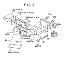
- Fig. 2 optically shows an embodiment of this invention wherein a masking plate 10 having a rectangular main aperture 11 and a pair of apertures for additional information 12A and 12B is provided in front of and close to a microfilm 20.
- a full/half mask 13 which is openable/ closable in the directions P and Q to determine the size of the main aperture 11.
- the microfilm When the images of the manuscript 6 are photographed on the microfilm, the microfilm is mechanically forced upward onto the masking plate 10 with a known pressing mechanism (not shown).
- the additional information corresponding to the recorded manuscript 6 is exposed with light on the microfilm 20 via the apertures 12A and 12B. More particularly, characters and figures are displayed in negative on the display units 31A and 31 B of a liquid crystal plate 30.
- Light sources 33A and 33B are provided behind the liquid crystal plate 30 via a diffusion plate 32 while a mirror 34 is provided in front thereof. The light reflected from the mirror 34 is illuminated on a mirror 36 via lens unit 35 and the light reflected -from the mirror 36 exposed the characters on the display units 31A and 31B via the apertures 12A and 12B onto the microfilm 20.
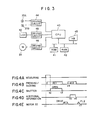
- Fig. 3 shows the control system of the above optical system wherein a CPU 40 such as a micro processor controls the whole system.
- a ROM 41 for program storage, a RAM 42 for data processing and a keyboard 43 for command input are connected to the CPU 40 via bus line.
- the CPU 40 is further connected to the light sources 33A and 33B via a driving circuit 44, to the liquid crystal plate 30 via a driving circuit 45 and to the motor 22 via a driving circuit 46.
- the display units 31A and 31 B of the liquid crystal plate 30 are respectively divided into three portions as shown in Fig. 2 which are driven by the driving circuit 45 as well as separately controlled by the CPU 40, and the light sources 33A and 33B are independently turned on and controlled.
- Fig. 4A through 4E show the exposing procedure for one frame chronologically from the start time point t1 to the completion time point t7.
- a photo sensor (not shown) photometrically measures the manuscript 6 by the time point t2 as shown in Fig. 4A, and exposure is determined based on the photometric data.
- the microfilm 20 is forced upon the masking plate 10 by a pressing/ sucking operation (AC1), which is conducted to effect focusing as shown in Fig. 4B. More specifically, such operation is conducted by a known pressing mechanism which mechanically presses the microfilm from above and by known suction mechanism which sucks the microfilm onto the masking plate 10 by means of air pressure of an air pump.
- a shutter (not shown) is opened and during the period from the time point t2 to the time point t3 in Fig. 4C, the microfilm 20 is exposed with the images of the manuscript 6.
- the full/half mask 13 is controlled positionally in advance determining the size of the main aperture 11 as full size or a half size.
- the images of the manuscript 6 are focused at a predetermined position on the microfilm 20 in a predetermined size and then exposed.
- the microfilm 20 is suspended and the pressing/sucking operation similar to the above is conducted from the time point t4 during the period AC2.
- the additional information relevant to the manuscript 6 is displayed on the display units 31A and 31B of the liquid crystal plate 30 via the CPU 40 and the driving circuit 45 while the light sources 33A and 33B are turned on via the CPU 40 and the driving circuit 44.
- the displayed data is reflected by the mirror 34, inputted to the lens unit 35, reflected again by the mirror 36 and exposed on the microfilm 20 via the apertures 12A and 12B (time points t5 to t6).
- the additional information is exposed at positions above and below the already exposed images of the manuscript 6.
- the microfilm 20 is moved by a predetermined length to finish the photographing operation for one frame and to prepare for the next manuscript as shown in Fig. 4E with FL2.
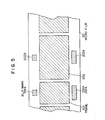
- Fig. 5 shows an example of the microfilm print which is imaged in the above mentioned manner wherein the images in a frame 201 are exposed in half-size while information on data 201A and a blip mark 201B are printed above and below the images in the frame 201. Similarly, the images in a frame 202 are exposed in full-size with data 202A and a blip mark 202B respectively printed.
- the information 201A and 202A and blip marks 201B and 202B are positioned substantially at center of the frames 201 and 202. They may arbitrarily be positioned by adjusting the feeding amount of the microfilm. The size of the information or of the blip marks may be arbitrarily varied by controlling the driving circuit 45 via the CPU 40.
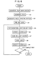
- This invention apparatus is operated in accordance with the flow chart shown in Fig. 6.
- Step S1 a blip mark system is designated (Step S1), and commands are inputted to indicate how many portions out of the three portions allocated to each display units 31A and 31 B, which will be also used to designate the siye of the marks.
- the frame size to be exposed is designated by driving the full/half mask 13 (Step S2), and the counting system for information is designated. More particularly, if the data relates to date, it is not necessary to change the data through a day, a period in which most of exposing operation is completed, but if the data is a serial number, it should be renewed or added by one for each frame (Step S3).
- Step S4 the initial value of the data (for instance, if the data is date, it may be "84.10.22” and if the data is a serial number, it may be "00001") is pre-set (Step S4).
- the shutter button on the keyboard 43 is pushed (Step S5).
- the motor 22 is actuated via the CPU 40 and the driving circuit 46 to convey the microfilm 20 by a predetermined length (Step S6).
- the light sources 33A and 33B are turned on via the driving circuit 44 (Step S7). This makes the content of the display units 31A and 31B to be exposed with light (Step S8).
- Step S9 the microfilm 20 is advanced by a predetermined length for the next photographing operation. Then, whether or not the operation is completed is judged (Step S10), and if is not completed, the procedure will return to Step S5 to repeat the operation similar to the above.
- liquid crystal plate and light sources are described as an additional information generator in the above explanation, it may be replaced with a self-light emitting type LED (light emitting diode) element, en EL (electroluminescence) plate, or a CRT display.
- the display of the additional information is described by means of two mirrors in the above, but it is structurally possible to use only one mirror. Alternatively, the additional information may be directly exposed on the microfilm surface through a lens without using mirrors.
- this invention permits information data or blip marks to be generated and exposed at an arbitrary position in correspondence with the frame images within a camera head.
- This invention also allows exposure of such data or marks at a predetermined position with a predetermined size irrespective of the size or the density of manuscript.
- this invention can achieve high efficiency with a simple structure.
- This invention apparatus does not require complex mechanical manipulation but is operated wholly with electric control to achieve simple but effective operation at a low cost.
Landscapes
- Physics & Mathematics (AREA)
- General Physics & Mathematics (AREA)
- Light Sources And Details Of Projection-Printing Devices (AREA)
- Projection-Type Copiers In General (AREA)
Description
- This invention relates to a micro-film camera for photographing images from a manuscript placed on a table according to the pre-characterizing part of Claim 1.
- As more and more information is needed in the society, image processing technology is increasingly in demand for recording documents and reference materials in microfilm, retrieving them when necessary, and projecting the information in enlargement, or duplicating them in hard copy. Fig. 1 shows a widely used microfilm photographing apparatus wherein a camera 1 with a focusing
lens 2 mounted on a supportingpole 3 moves up and down along the supportingpole 3 so as to include a manuscript (including document, microfilm and so on) 6 placed on a table 7 withinvisional fields manuscript 6 on a microfilm frame by frame.Lights control box 8 are directed to themanuscript 6 so that themanuscript 6 is constantly illuminated with a given amount of light. - The microfilm recorded in the above manner should be stored in a systematic and easy-to-use manner to allow quick retrieval for effective use. In order to facilitate such systematic storage and later retrieval, it is necessary to record additional information in correspondence to each frame of images on the microfilm. Blip marks, serial numbers indicating frame number, dates of recording, etc. are generally used as such additional information which are conventionally provided at a location close to the
manuscript 6 within thevisual fields manuscript 6. Figures in the additional information frame are replaced for recording images of each frame. This method, however, involves replacing figures or characters for every recording. Moreover, as optical magnification changes depending on the size of manuscript or of film, the size of the recorded additional information on the microfilm becomes inconsistent if the characters of the same size are used. On the other hand, if the size of the characters is changed in correspondence to the size of manuscript, the operation becomes more complicated. - There has been proposed another method which rotates character gears interlockingly with feeding of microfilm in the camera 1 so that serial number is photographed together with the manuscript. However, such character gears can be provided only at a predetermined location in relation to the image frames.
- In accordance with the pre-characterizing part of Claim 1, DE-32 16 802 A1 discloses a microfilm-camera in which the additional information generator is in the form of a keyboard. Additional information being printed on the manuscript is read by an operator and keyed in via the keyboard. This input additional information is displayed on a CRT for illuminating a coding portion which forms part of a microfiche portion of a microfiche card.
- DE-26 33 657 A1 discloses a similar microfilm-camera. Additional information is generated by means of an optical path including means comprising a first mirror, a lens and a second mirror for directing additional information onto an edge portion of a microfilm.
- DE-21 18 732 discloses an apparatus for photographing microfilms including means for storing additional information on the microfilm. An array of lamps is disposed at the travelling path of the microfilm and by suitably switching the lamps, additional information is stored on the microfilm.
- The problem underlying the present invention is to provide a microfilm-camera which can generally be applied to various types of retrieval apparatuses and which allows exposure of the microfilm to additional information with simple operation.
- In accordance with the present invention, this problem is solved by the features of the characterizing part of Claim 1.
- In accordance with the invention, a liquid crystal plate is suitably driven to optically generate additional information which is directed via a lens and mirrors onto a microfilm. Between the microfilm and an optical path controlling means mask plates are disposed to selectively expose the microfilm to the additional information only at predetermined positions.
- The invention will now be described with reference to the accompanying drawings in which:
- Fig. 1 is a schematic view of microfilm-camera to which the present invention can be applied.
- Fig. 2 is an optical view to show one embodiment of this invention;
- Fig. 3 is a block diagram to show the control system thereof;
- Figs. 4A through 4E are timing charts to show operational modes thereof;
- Fig. 5 is a view to show a microfilm printed, and
- Fig. 6 is a flow chart to show an example of the operation according to this invention.
- Fig. 2 optically shows an embodiment of this invention wherein a
masking plate 10 having a rectangular main aperture 11 and a pair of apertures foradditional information microfilm 20. At the downstream of themasking plate 10 is provided a full/half mask 13 which is openable/ closable in the directions P and Q to determine the size of the main aperture 11. When themanuscript 6 is focused by thelens 2 and a shutter button (described hereinafter) is pushed down, themicrofilm 20 is exposed with light via the main aperture 11. Themicrofilm 20 is adapted to be coiled on aroller 21 driven by amotor 22. When the images of themanuscript 6 are photographed on the microfilm, the microfilm is mechanically forced upward onto themasking plate 10 with a known pressing mechanism (not shown). The additional information corresponding to the recordedmanuscript 6 is exposed with light on themicrofilm 20 via theapertures display units liquid crystal plate 30.Light sources liquid crystal plate 30 via adiffusion plate 32 while amirror 34 is provided in front thereof. The light reflected from themirror 34 is illuminated on amirror 36 vialens unit 35 and the light reflected -from themirror 36 exposed the characters on thedisplay units apertures microfilm 20. - Fig. 3 shows the control system of the above optical system wherein a
CPU 40 such as a micro processor controls the whole system. AROM 41 for program storage, aRAM 42 for data processing and akeyboard 43 for command input are connected to theCPU 40 via bus line. TheCPU 40 is further connected to thelight sources driving circuit 44, to theliquid crystal plate 30 via adriving circuit 45 and to themotor 22 via adriving circuit 46. Thedisplay units liquid crystal plate 30 are respectively divided into three portions as shown in Fig. 2 which are driven by thedriving circuit 45 as well as separately controlled by theCPU 40, and thelight sources - The operation of the apparatus with above mentioned structure will now be described referring to the timing chart shown in Fig. 4A through 4E.
- Fig. 4A through 4E show the exposing procedure for one frame chronologically from the start time point t1 to the completion time point t7. When the operation starts at the time point t1 is commanded from the
keyboard 43, a photo sensor (not shown) photometrically measures themanuscript 6 by the time point t2 as shown in Fig. 4A, and exposure is determined based on the photometric data. Meanwhile, themicrofilm 20 is forced upon themasking plate 10 by a pressing/ sucking operation (AC1), which is conducted to effect focusing as shown in Fig. 4B. More specifically, such operation is conducted by a known pressing mechanism which mechanically presses the microfilm from above and by known suction mechanism which sucks the microfilm onto themasking plate 10 by means of air pressure of an air pump. After the time point t2 on the completion of the photometric measurement, a shutter (not shown) is opened and during the period from the time point t2 to the time point t3 in Fig. 4C, themicrofilm 20 is exposed with the images of themanuscript 6. The full/half mask 13 is controlled positionally in advance determining the size of the main aperture 11 as full size or a half size. The images of themanuscript 6 are focused at a predetermined position on themicrofilm 20 in a predetermined size and then exposed. When the shutter is closed to complete exposure at the time point t3, the operation AC1 of pressing and sucking themicrofilm 20 ends and themotor 22 is activated via the CPU 40 (FL1 of Fig. 4E), and themicrofilm 20 is wound on theroller 21. When the portion of the microfilm which has just been recorded comes at the center of theapertures microfilm 20 is suspended and the pressing/sucking operation similar to the above is conducted from the time point t4 during the period AC2. During the operation AC2, the additional information relevant to themanuscript 6 is displayed on thedisplay units liquid crystal plate 30 via theCPU 40 and thedriving circuit 45 while thelight sources CPU 40 and thedriving circuit 44. The displayed data is reflected by themirror 34, inputted to thelens unit 35, reflected again by themirror 36 and exposed on themicrofilm 20 via theapertures manuscript 6. Themicrofilm 20 is moved by a predetermined length to finish the photographing operation for one frame and to prepare for the next manuscript as shown in Fig. 4E with FL2. - Fig. 5 shows an example of the microfilm print which is imaged in the above mentioned manner wherein the images in a
frame 201 are exposed in half-size while information ondata 201A and ablip mark 201B are printed above and below the images in theframe 201. Similarly, the images in aframe 202 are exposed in full-size withdata 202A and ablip mark 202B respectively printed. In this example, theinformation frames circuit 45 via theCPU 40. - This invention apparatus is operated in accordance with the flow chart shown in Fig. 6.
- When the operation starts, a blip mark system is designated (Step S1), and commands are inputted to indicate how many portions out of the three portions allocated to each
display units keyboard 43 is pushed (Step S5). Themotor 22 is actuated via theCPU 40 and the drivingcircuit 46 to convey themicrofilm 20 by a predetermined length (Step S6). Thelight sources display units microfilm 20 is advanced by a predetermined length for the next photographing operation (Step S9). Then, whether or not the operation is completed is judged (Step S10), and if is not completed, the procedure will return to Step S5 to repeat the operation similar to the above. - Although a combination of a liquid crystal plate and light sources is described as an additional information generator in the above explanation, it may be replaced with a self-light emitting type LED (light emitting diode) element, en EL (electroluminescence) plate, or a CRT display. The display of the additional information is described by means of two mirrors in the above, but it is structurally possible to use only one mirror. Alternatively, the additional information may be directly exposed on the microfilm surface through a lens without using mirrors.
- As described in detail in the foregoing statement, this invention permits information data or blip marks to be generated and exposed at an arbitrary position in correspondence with the frame images within a camera head. This invention also allows exposure of such data or marks at a predetermined position with a predetermined size irrespective of the size or the density of manuscript. As one microfilm photographing apparatus can be adapted universally for various formats, this invention can achieve high efficiency with a simple structure. This invention apparatus does not require complex mechanical manipulation but is operated wholly with electric control to achieve simple but effective operation at a low cost.
- It should be understood that many modifications and adaptations of the invention will become apparent to those skilled in the art and it is intended to encompass such obvious modifications and changes in the scope of the claims appended hereto.
Claims (5)
Applications Claiming Priority (4)
| Application Number | Priority Date | Filing Date | Title |
|---|---|---|---|
| JP268101/84 | 1984-12-19 | ||
| JP26810184A JPS61145538A (en) | 1984-12-19 | 1984-12-19 | Microfilm photographing device |
| JP26810284A JPS61145539A (en) | 1984-12-19 | 1984-12-19 | Photographing method of microfilm |
| JP268102/84 | 1984-12-19 |
Publications (3)
| Publication Number | Publication Date |
|---|---|
| EP0186859A2 EP0186859A2 (en) | 1986-07-09 |
| EP0186859A3 EP0186859A3 (en) | 1986-07-30 |
| EP0186859B1 true EP0186859B1 (en) | 1990-06-13 |
Family
ID=26548168
Family Applications (1)
| Application Number | Title | Priority Date | Filing Date |
|---|---|---|---|
| EP85116170A Expired - Lifetime EP0186859B1 (en) | 1984-12-19 | 1985-12-18 | Microfilmcamera |
Country Status (3)
| Country | Link |
|---|---|
| US (1) | US4701046A (en) |
| EP (1) | EP0186859B1 (en) |
| DE (1) | DE3578232D1 (en) |
Families Citing this family (14)
| Publication number | Priority date | Publication date | Assignee | Title |
|---|---|---|---|---|
| CH672550A5 (en) * | 1986-04-25 | 1989-11-30 | Noritsu Kenkyu Center Co | DEVICE FOR INSERTING A PAPER MASK IN A PHOTOGRAPHIC PRINTER. |
| US4785333A (en) * | 1986-06-20 | 1988-11-15 | Fuji Photo Film Co., Ltd. | Blip marking recorder in a microfilm duplicating apparatus |
| US4803505A (en) * | 1986-09-03 | 1989-02-07 | Minolta Camera Kabushiki Kaisha | Microfilm camera |
| JPS6388542A (en) * | 1986-10-01 | 1988-04-19 | Canon Inc | image recording device |
| US4901108A (en) * | 1986-11-29 | 1990-02-13 | Minolta Camera Kabushiki Kaisha | Microfilming apparatus |
| US4897943A (en) * | 1987-03-18 | 1990-02-06 | Fuji Photo Film Co., Ltd. | Photographic display and apparatus for making elemental prints of the same |
| JPH01255846A (en) * | 1988-04-06 | 1989-10-12 | Minolta Camera Co Ltd | Microfilm camera |
| EP1033611B1 (en) * | 1988-08-31 | 2003-10-15 | Sony Corporation | Photographic camera systems and film cassettes |
| US4984008A (en) * | 1989-04-28 | 1991-01-08 | Bell & Howell Company | Film number writing system |
| US5173731A (en) * | 1990-06-08 | 1992-12-22 | Canon Kabushiki Kaisha | Recording apparatus |
| EP0580129B1 (en) * | 1992-07-20 | 1997-01-15 | Fuji Photo Film Co., Ltd. | Photographic film analyzer with simulator and film inspecting method |
| EP0589420A3 (en) * | 1992-09-21 | 1994-05-18 | Nippon Kogaku Kk | Data imprinting device for a camera |
| GB2288250B (en) * | 1994-03-30 | 1998-04-29 | Motorola Inc | Semiconductor device fabrication method |
| US5646713A (en) * | 1995-06-13 | 1997-07-08 | Eastman Kodak Company | Apparatus and method for exposing data characters onto a strip region of moving photosensitive media |
Citations (4)
| Publication number | Priority date | Publication date | Assignee | Title |
|---|---|---|---|---|
| DE2118732B2 (en) * | 1971-04-17 | 1977-02-17 | Agfa-Gevaert Ag, 5090 Leverkusen | Microfilm appts. operative for exposing moving originals - includes system for producing line marks on microfilms |
| DE2633657A1 (en) * | 1976-03-30 | 1977-10-13 | Geb Vannet Germaine Gresset | PROCESS OF ENCRYPTION OF THE IMAGES OF A FILM WITH THE HELP OF CHARACTERS RECORDED ON THE TAPE WINDOWS AND BETWEEN THE PERFORATIONS |
| US4361388A (en) * | 1980-12-19 | 1982-11-30 | Carl Zeiss-Stiftung | Digital-marking camera attachment |
| DE3216802A1 (en) * | 1982-05-05 | 1983-11-10 | Dr. Welp Entwicklungs-Kg, 6350 Bad Nauheim | Method for producing microfilm cards, a microfilm card produced in accordance with this method, and a device for carrying out the method |
Family Cites Families (14)
| Publication number | Priority date | Publication date | Assignee | Title |
|---|---|---|---|---|
| BE631274A (en) * | 1962-12-10 | |||
| US3263555A (en) * | 1963-05-13 | 1966-08-02 | Harold A Scheib | Optical film printer having means to print edge numbers within the picture area |
| US3674365A (en) * | 1969-10-22 | 1972-07-04 | Agfa Gevaert Ag | Photographic printing apparatus |
| US3824604A (en) * | 1972-10-12 | 1974-07-16 | E Stein | Alphanumeric printing system employing liquid crystal matrix |
| DD103064A1 (en) * | 1972-11-08 | 1974-01-05 | ||
| AU7214974A (en) * | 1973-08-15 | 1976-02-12 | Spence Bate | Camera |
| US4029412A (en) * | 1974-10-08 | 1977-06-14 | Spence Bate | Multi-standard reprographic camera |
| IT1070455B (en) * | 1976-09-10 | 1985-03-29 | Sidam Srl | CAMERA FOR THE PERFORMANCE OF IDENTIFICATION CARDS WITH PORTRAIT..PARTICALLY FOR AUTOMATIC CAMERA INCLUDING IMMEDIATE TREATMENT PLANTS OF THE EXPOSED PHOTOSENSITIVE MATERIAL |
| US4087175A (en) * | 1977-02-16 | 1978-05-02 | Bell & Howell Company | Automatic microfilm camera operated responsive to data input at a computer terminal |
| US4174174A (en) * | 1977-03-15 | 1979-11-13 | Xerox Corporation | Composing reducing camera |
| DE2738236C2 (en) * | 1977-08-25 | 1982-05-06 | Agfa-Gevaert Ag, 5090 Leverkusen | Photographic copier |
| US4193684A (en) * | 1978-05-12 | 1980-03-18 | Armstrong Alvin H | Photographic printing and print identifying apparatus |
| DE3132633C2 (en) * | 1980-11-07 | 1989-01-12 | Hermann 7742 St Georgen Stockburger | Method and device for registering the use of copiers |
| DE3043068C2 (en) * | 1980-11-14 | 1984-04-19 | Agfa-Gevaert Ag, 5090 Leverkusen | Apparatus for projecting a license plate image onto film |
-
1985
- 1985-12-18 DE DE8585116170T patent/DE3578232D1/en not_active Expired - Lifetime
- 1985-12-18 EP EP85116170A patent/EP0186859B1/en not_active Expired - Lifetime
- 1985-12-19 US US06/810,712 patent/US4701046A/en not_active Expired - Lifetime
Patent Citations (4)
| Publication number | Priority date | Publication date | Assignee | Title |
|---|---|---|---|---|
| DE2118732B2 (en) * | 1971-04-17 | 1977-02-17 | Agfa-Gevaert Ag, 5090 Leverkusen | Microfilm appts. operative for exposing moving originals - includes system for producing line marks on microfilms |
| DE2633657A1 (en) * | 1976-03-30 | 1977-10-13 | Geb Vannet Germaine Gresset | PROCESS OF ENCRYPTION OF THE IMAGES OF A FILM WITH THE HELP OF CHARACTERS RECORDED ON THE TAPE WINDOWS AND BETWEEN THE PERFORATIONS |
| US4361388A (en) * | 1980-12-19 | 1982-11-30 | Carl Zeiss-Stiftung | Digital-marking camera attachment |
| DE3216802A1 (en) * | 1982-05-05 | 1983-11-10 | Dr. Welp Entwicklungs-Kg, 6350 Bad Nauheim | Method for producing microfilm cards, a microfilm card produced in accordance with this method, and a device for carrying out the method |
Also Published As
| Publication number | Publication date |
|---|---|
| US4701046A (en) | 1987-10-20 |
| DE3578232D1 (en) | 1990-07-19 |
| EP0186859A2 (en) | 1986-07-09 |
| EP0186859A3 (en) | 1986-07-30 |
Similar Documents
| Publication | Publication Date | Title |
|---|---|---|
| US5563984A (en) | Method and apparatus for printing images | |
| CA1275002A (en) | Electronic imaging copier | |
| EP0235202B1 (en) | Film video player/printer | |
| EP0225762B1 (en) | Electronic imaging copier | |
| EP0821265B1 (en) | Method of making photographic prints | |
| US4701046A (en) | Method of photographing on microfilm and apparatus therefor | |
| EP0629908A2 (en) | High speed index printer | |
| US5160952A (en) | Print control apparatus | |
| US6571067B2 (en) | Photographic camera system | |
| JPH03504541A (en) | Method and apparatus for recording and using exposure data in a photographic system | |
| US5752109A (en) | Photographic camera system | |
| US5784658A (en) | Optical data recording device of camera and lens-fitted photographic film unit | |
| US4200392A (en) | Photographic copy apparatus with cropping feature | |
| US5742854A (en) | Photographic camera | |
| JPH037926A (en) | Print information recording device | |
| JP3766537B2 (en) | FILM UNIT WITH LENS AND PRINT PHOTO CREATION METHOD | |
| JPH05323469A (en) | Image synthesis printer | |
| JP2704628B2 (en) | Certificate creation system | |
| JP2745263B2 (en) | Micro film camera | |
| JPS627036A (en) | Photographing mask for microcamera | |
| JPH0351838A (en) | Intended composition recording camera and photographic printer | |
| JPS61145538A (en) | Microfilm photographing device | |
| JPH07248544A (en) | Photographic printing machine | |
| JPS61145539A (en) | Photographing method of microfilm | |
| JPS60500032A (en) | movie style camera |
Legal Events
| Date | Code | Title | Description |
|---|---|---|---|
| PUAI | Public reference made under article 153(3) epc to a published international application that has entered the european phase |
Free format text: ORIGINAL CODE: 0009012 |
|
| PUAL | Search report despatched |
Free format text: ORIGINAL CODE: 0009013 |
|
| AK | Designated contracting states |
Kind code of ref document: A2 Designated state(s): DE GB |
|
| RHK1 | Main classification (correction) |
Ipc: G03B 17/24 |
|
| AK | Designated contracting states |
Kind code of ref document: A3 Designated state(s): DE GB |
|
| 17P | Request for examination filed |
Effective date: 19870105 |
|
| 17Q | First examination report despatched |
Effective date: 19880420 |
|
| GRAA | (expected) grant |
Free format text: ORIGINAL CODE: 0009210 |
|
| AK | Designated contracting states |
Kind code of ref document: B1 Designated state(s): DE GB |
|
| REF | Corresponds to: |
Ref document number: 3578232 Country of ref document: DE Date of ref document: 19900719 |
|
| PLBE | No opposition filed within time limit |
Free format text: ORIGINAL CODE: 0009261 |
|
| STAA | Information on the status of an ep patent application or granted ep patent |
Free format text: STATUS: NO OPPOSITION FILED WITHIN TIME LIMIT |
|
| 26N | No opposition filed | ||
| REG | Reference to a national code |
Ref country code: GB Ref legal event code: IF02 |
|
| PGFP | Annual fee paid to national office [announced via postgrant information from national office to epo] |
Ref country code: GB Payment date: 20021126 Year of fee payment: 18 |
|
| PGFP | Annual fee paid to national office [announced via postgrant information from national office to epo] |
Ref country code: DE Payment date: 20030219 Year of fee payment: 18 |
|
| PG25 | Lapsed in a contracting state [announced via postgrant information from national office to epo] |
Ref country code: GB Free format text: LAPSE BECAUSE OF NON-PAYMENT OF DUE FEES Effective date: 20031218 |
|
| PG25 | Lapsed in a contracting state [announced via postgrant information from national office to epo] |
Ref country code: DE Free format text: LAPSE BECAUSE OF NON-PAYMENT OF DUE FEES Effective date: 20040701 |
|
| GBPC | Gb: european patent ceased through non-payment of renewal fee |
Effective date: 20031218 |