EP0186774A2 - Door plug for coke oven doors - Google Patents
Door plug for coke oven doors Download PDFInfo
- Publication number
- EP0186774A2 EP0186774A2 EP85114837A EP85114837A EP0186774A2 EP 0186774 A2 EP0186774 A2 EP 0186774A2 EP 85114837 A EP85114837 A EP 85114837A EP 85114837 A EP85114837 A EP 85114837A EP 0186774 A2 EP0186774 A2 EP 0186774A2
- Authority
- EP
- European Patent Office
- Prior art keywords
- door
- coke oven
- plates
- stopper according
- ceramic
- Prior art date
- Legal status (The legal status is an assumption and is not a legal conclusion. Google has not performed a legal analysis and makes no representation as to the accuracy of the status listed.)
- Granted
Links
- 239000000571 coke Substances 0.000 title claims abstract description 22
- 239000000919 ceramic Substances 0.000 claims abstract description 24
- 229910010293 ceramic material Inorganic materials 0.000 claims abstract description 11
- 238000004939 coking Methods 0.000 claims abstract description 5
- XEEYBQQBJWHFJM-UHFFFAOYSA-N Iron Chemical compound [Fe] XEEYBQQBJWHFJM-UHFFFAOYSA-N 0.000 claims description 31
- 229910052742 iron Inorganic materials 0.000 claims description 14
- 229910000831 Steel Inorganic materials 0.000 claims description 13
- 239000010959 steel Substances 0.000 claims description 13
- 238000000034 method Methods 0.000 claims description 3
- UQSXHKLRYXJYBZ-UHFFFAOYSA-N Iron oxide Chemical compound [Fe]=O UQSXHKLRYXJYBZ-UHFFFAOYSA-N 0.000 abstract description 8
- VYPSYNLAJGMNEJ-UHFFFAOYSA-N Silicium dioxide Chemical compound O=[Si]=O VYPSYNLAJGMNEJ-UHFFFAOYSA-N 0.000 abstract description 6
- TWNQGVIAIRXVLR-UHFFFAOYSA-N oxo(oxoalumanyloxy)alumane Chemical compound O=[Al]O[Al]=O TWNQGVIAIRXVLR-UHFFFAOYSA-N 0.000 abstract description 2
- 235000012239 silicon dioxide Nutrition 0.000 abstract 2
- 239000000377 silicon dioxide Substances 0.000 abstract 2
- 229910017344 Fe2 O3 Inorganic materials 0.000 abstract 1
- 229910052681 coesite Inorganic materials 0.000 abstract 1
- 239000000470 constituent Substances 0.000 abstract 1
- 229910052906 cristobalite Inorganic materials 0.000 abstract 1
- 230000000149 penetrating effect Effects 0.000 abstract 1
- 229910052682 stishovite Inorganic materials 0.000 abstract 1
- 229910052905 tridymite Inorganic materials 0.000 abstract 1
- 239000007789 gas Substances 0.000 description 16
- 230000001681 protective effect Effects 0.000 description 8
- 229910052751 metal Inorganic materials 0.000 description 6
- 239000002184 metal Substances 0.000 description 6
- 238000007789 sealing Methods 0.000 description 2
- 229910052814 silicon oxide Inorganic materials 0.000 description 2
- 238000009825 accumulation Methods 0.000 description 1
- 239000000956 alloy Substances 0.000 description 1
- 229910045601 alloy Inorganic materials 0.000 description 1
- 239000003245 coal Substances 0.000 description 1
- 238000001816 cooling Methods 0.000 description 1
- 238000013461 design Methods 0.000 description 1
- 238000011161 development Methods 0.000 description 1
- 238000007599 discharging Methods 0.000 description 1
- 238000006073 displacement reaction Methods 0.000 description 1
- 238000002474 experimental method Methods 0.000 description 1
- 230000002349 favourable effect Effects 0.000 description 1
- 238000009413 insulation Methods 0.000 description 1
- 235000000396 iron Nutrition 0.000 description 1
- 239000000463 material Substances 0.000 description 1
- 239000011490 mineral wool Substances 0.000 description 1
- 238000001556 precipitation Methods 0.000 description 1
- 238000012545 processing Methods 0.000 description 1
- 230000005855 radiation Effects 0.000 description 1
- 230000000717 retained effect Effects 0.000 description 1
- 238000005382 thermal cycling Methods 0.000 description 1
- 210000002268 wool Anatomy 0.000 description 1
Images


Classifications
-
- C—CHEMISTRY; METALLURGY
- C10—PETROLEUM, GAS OR COKE INDUSTRIES; TECHNICAL GASES CONTAINING CARBON MONOXIDE; FUELS; LUBRICANTS; PEAT
- C10B—DESTRUCTIVE DISTILLATION OF CARBONACEOUS MATERIALS FOR PRODUCTION OF GAS, COKE, TAR, OR SIMILAR MATERIALS
- C10B25/00—Doors or closures for coke ovens
- C10B25/02—Doors; Door frames
- C10B25/06—Doors; Door frames for ovens with horizontal chambers
Definitions
- the invention relates to door plugs for coke oven doors, which are made of ceramic material and are held at a distance from the coke oven door. In the operating state, the plugs then protrude into the furnace chamber and hold the furnace filling at a certain distance from the door body, the door body being pressed against the door frame of the furnace with a locking device during the coking process.
- the metallic door stopper is the door stopper known from German Patent 23 83 63.
- This door stopper is formed by an adjustable protective shield attached to the rear wall of the coke oven door, which is connected to the rear of the door via articulated intermediate elements and can move in relation to the door.
- the invention has for its object to avoid the operating difficulties of current metallic door plugs.
- the invention again uses ceramic material by using ceramic plates with a thickness of 35 to 120 mm.
- ceramic material is suitable.
- a hydraulically binding refractory concrete is provided.
- the essential components of this refractory concrete are aluminum oxide, silicon oxide and iron oxide.
- the proportion of iron oxide (A1 2 0 3 ) is preferably 40-55%, the proportion of silicon oxide (Si0 2 ) between 40 and 50%, the proportion of iron oxide (Fe 2 0 3 ) between 0.5 and 1.5% .
- a ratio of thickness to plate width of 1: 3 to 1:20 can result.
- the ceramic plate consists of interchangeable elements.
- the interchangeable elements are optionally arranged one above the other and are each held in a metal frame.
- the metal frames are attached individually, e.g. B. with welded carrying iron. This allows simple and easy replacement of the ceramic elements in the event of damage.
- the metal support frames are preferably fastened to the door in an adjustable manner. This is done by means of suitable carrier iron or counter carrier, which are screwed or wedged together. In the case of screwing, elongated holes are provided for adjustment.
- the door leaf of the coke oven door is expediently provided with an insulating layer, which heats up the door and the associated high heat radiation, i. H. Loss of heat and heat load on the operators are prevented.
- the insulation layer is 50 - 100 mm thick.
- the ceramic plate protrudes into the furnace chamber to the extent that the furnace filling is retained as much as with conventional ceramic plugs.
- the adjustability also allows the ceramic plates to be taken back and the associated furnace space to be enlarged.
- the respective position of the Ceramic plate can also result from an optimized arrangement with respect to the last Schuzu g in the coke oven walls.
- the desired large gas collecting space arises in the ceramic plate according to the invention behind the metallic support frame, i. H. between the ceramic plate and the insulating layer.
- FIG. 1 shows a cross section through a door plug according to the invention with a coke oven door.
- a ceramic plate is designated, the ceramic plate is held adjustable in a heat-resistant steel frame 2 with three welded-on carrying iron 3.
- Retaining anchors 4 are formed in the ceramic front plate as connecting elements to the metal frame 2.
- the holding anchors 4 are shown in broken lines.
- the ceramic material is either:
- the straps are held on counter straps 5, which in turn are screwed to the coke oven door.
- the counter brackets 5 have 1 elongated holes 9 for adjusting the ceramic front plate.
- the mounting brackets 3 are fastened to the counter brackets 5 by means of screws or wedges.
- the coke oven door 8 is protected with an insulating layer 7 against excessive heat load.
- the insulating layer 7 is again made of ceramic material. When using ceramic material, it is molded on and preferably secured by holding anchors 10. The holding anchors 10 are again shown in broken lines.
- a door stopper is composed of a plurality of front plates 1 arranged one above the other.
- the carrier iron 3 and counter carrier 5 are located at the top and bottom of the metal frame belonging to the ceramic front plates 1. This advantageously allows the use of a counter arm 5 at the same time for two opposing iron bars 3.
- the three attachment points one is arranged on the center line of the coke oven door. The other two are on either side of the center line. This is shown in Figure 3.
- Each support iron and counter support iron can form the attachment for two adjacent corners of two adjacent ceramic plates.
- FIG. 4 shows a section through a fastening point with two carrying irons 3 opposite one another and a counter carrying iron 5.
- the gas channel between the stopper and the door is closed with mineral wool or the like. This wool is removed from the mold after it has been sufficiently heated.
- the ceramic signs are provided with plates 20, which are each fastened at four corners.
- Each carrying iron also forms a fastening for a plate 20 arranged above and underneath. While the fastening to the upper plate corners takes place with positive and positive locking, the fastening to the lower plate corners permits a displacement in longitudinal slots in accordance with the thermal expansion. The associated fastening screws are loose. A complete loosening is prevented by lock nuts.
- the plates are drawn in at 23 below and the fastening points are covered by edge stones 24.
- the edge stones 24 are also held by the carrying iron 21.
Landscapes
- Chemical & Material Sciences (AREA)
- Engineering & Computer Science (AREA)
- Materials Engineering (AREA)
- Oil, Petroleum & Natural Gas (AREA)
- Organic Chemistry (AREA)
- Coke Industry (AREA)
- Furnace Housings, Linings, Walls, And Ceilings (AREA)
- Heterocyclic Carbon Compounds Containing A Hetero Ring Having Oxygen Or Sulfur (AREA)
Abstract
Description
Die Erfindung betrifft Türstopfen für Koksofentüren, die aus keramischem Material bestehen und im Abstand an der Koksofentür gehalten werden. Im Betriebszustand ragen die Stopfen dann in die Ofenkammer hinein und halten die Ofenfüllung in einem bestimmten Abstand vom Türkörper, wobei der Türkörper während des Verkokungsvorganges mit einer Verriegelungseinrichtung gegen den Türrahmen des Ofens gedrückt wird.The invention relates to door plugs for coke oven doors, which are made of ceramic material and are held at a distance from the coke oven door. In the operating state, the plugs then protrude into the furnace chamber and hold the furnace filling at a certain distance from the door body, the door body being pressed against the door frame of the furnace with a locking device during the coking process.
Anfang dieses Jahrhunderts gab es sowohl metallische Türstopfen, als auch keramische Türstopfen. Beispielhaft für die metallischen Türstopfen steht der aus der Deutschen Patentschrift 23 83 63 bekannte Türstopfen. Dieser Türstopfen wird durch einen an der Rückwand der Koksofentür angebrachten, verstellbaren Schutzschild gebildet, der über gelenkige Zwischenglieder mit der Rückseite der Tür verbunden ist und sich gegenüber der Tür bewegen kann.At the beginning of this century there were both metallic door plugs and ceramic door plugs. An example of the metallic door stopper is the door stopper known from
Die metallischen Türstopfen konnten sich jedoch nicht durchsetzen. Dies war vielmehr bei den keramischen Türstopfen der Fall. Lediglich Ende der 20er Jahre gab es den Versuch einer Verwendung von Stahl am Türstopfen, und zwar in Form eines Mantels. Aufgabe des Mantels war u.a., Wärmestauungen am Türstopfen zu verhindern und einen großen Gaskanal zu bilden. Der große Gaskanal war vorteilhaft für die Entlastung der Türdichtungen, indem das Gas zum Gassammelraum abgeführt wurde. Dieser Türstopfen ist in der Deutschen Patentschrift 48 92 49 veröffentlicht.However, the metallic door plugs could not prevail. Rather, this was the case with the ceramic door plugs. Only in the late 1920s was there an attempt to use steel on the door plug, in the form of a jacket. One of the tasks of the jacket was to prevent heat accumulation at the door plug and to form a large gas channel. The large gas channel was advantageous for relieving the pressure on the door seals by discharging the gas to the gas collecting space. This door stopper is published in German Patent 48 92 49.
Ende der 70er Jahre wurde dann in der Bundesrepublik Deutschland und USA der Gedanke der Verwendung von Stahl für Türstopfen erneut aufgegriffen. Beispielhaft stehen dafür die aus der Deutschen Offenlegungsschrift 29 45 017 bekannten Stahlstopfen bzw. die aus der US-Patentschrift 40 86 145 bekannten Schutzschilde aus Stahl. Diese ersten Versuche der Verwendung von Stahlstopfen haben sich im Betrieb wiederum nicht bewährt, jedoch eine unter bestimmten Be- dingungen brauchbare Weiterentwicklung angeregt. Im Rahmen dieser Entwicklung sind Türstopfen in Form von metallischen Schutzschilden entstanden, die ein- oder mehrteilig ausgebildet sind. D.h. entweder erstrecken sich die Schutzschilde über die ganze Länge der Koksofentür einteilig oder sind sie aus mehreren Schüssen zusammengesetzt. Ein wesentliches Problem der metallischen Schutzschilde ist die Wärmedehnung. Die Wärmedehnung von Metall gegenüber keramischem Material bedingt, daß die Türstopfen ein relativ großes Spiel in der Ofenkammer aufweisen müssen. Sonst würden sie sich nach der Abkühlung beim Koksdrücken im Ofen infolge ihrer durch die Wärmedehnung verursachten Volumenvergrößerung festsetzen. Beim Füllen der Koksöfen ist die Temperatur der Schutzschilde noch relativ gering. Das hat bei dem erläuterten großen Spiel zur Folge, daß feinkörniges und insbesondere trockenes Einsatzgut an dem Schutzschild vorbei in den Rohgaskanal zwischen Schutzschild und Tür dringt. Das führt sowohl zu Verstopfungen des Kanals und verhindert eine ausreichende Abführung des entstehenden Rohgases in den Gassammelkanal oben in der Ofenkammer als auch zu Leckagen. Die Leckagen entstehen durch ungünstige Temperaturverhältnisse und Freiwerden von Gasen bzw. Niederschlagen von Gasen an den Dichtflächen der Koksofentür. Nach dem Ausheben der Ofentür müssen die Gaskanäle dann mühsam von Hand gereinigt werden.At the end of the 1970s, the idea of using steel for door plugs was taken up again in the Federal Republic of Germany and the USA. Examples of this are the steel plugs known from German Offenlegungsschrift 29 45 017 and the steel protective shields known from US Pat. No. 40 86 145. These first experiments using steel plugs have again not proven in operation, however, suggested a dingun under certain loading g s useful development. As part of this Ent door plugs in the form of metallic protective shields, which are made in one or more parts. That means either the protective shields extend in one piece over the entire length of the coke oven door or they are composed of several shots. Thermal expansion is a major problem with metallic protective shields. The thermal expansion of metal compared to ceramic material means that the door plugs must have a relatively large amount of play in the furnace chamber. Otherwise they would get stuck after the coke press cooling in the furnace due to their volume expansion caused by thermal expansion. When filling the coke ovens, the temperature of the protective shields is still relatively low. In the large game explained, this has the consequence that fine-grained and, in particular, dry insert material penetrates past the protective shield into the raw gas channel between the protective shield and the door. This leads to blockages in the channel and prevents sufficient discharge of the resulting raw gas into the gas collection channel at the top of the furnace chamber, as well as to leakages. The leaks are caused by unfavorable temperature conditions and the release of gases or the precipitation of gases on the sealing surfaces of the coke oven door. After the furnace door has been lifted out, the gas ducts must then be laboriously cleaned by hand.
Ein weiteres Problem der metallischen Stopfen ist die Verformung.. Je nach Ausbildung der metallischen Stopfen entsteht eine starke Einwärts- oder Auswärtswölbung. Hinzukommt, daß alle Stahlsorten bei der extremen Wärmewechselbelastung bleibende Verformungen zeigen. Als Stahl kann nur hoch hitzebeständiger Stahl verwertet werden, dessen spezielle Legierungsbestandteile die Verarbeitung sehr schwierig gestalten.Another problem with the metallic plugs is the deformation. Depending on the design of the metallic plugs, there is a strong inward or outward curvature. In addition, all types of steel show permanent deformations under extreme thermal cycling. Only highly heat-resistant steel can be used as steel, the special alloy components of which make processing very difficult.
Ein Vorteil der metallischen Türstopfen ist die in der Deutschen Offenlegungsschrift 29 45 017 bereits beschriebene Vergrößerung des Ofenraumes. Außerdem zeigt sich, daß ein stark erweiterter Gaskanal, wie er beispielsweise aus der Deutschen Patentschrift 23 83 63 erkennbar ist,Betriebsvorteile durch Entlastung der Dichtflächen zeigt.One advantage of metallic door plugs is the enlargement of the furnace space, as already described in German Offenlegungsschrift 29 45 017. It also shows that a greatly expanded gas channel, as can be seen, for example, from
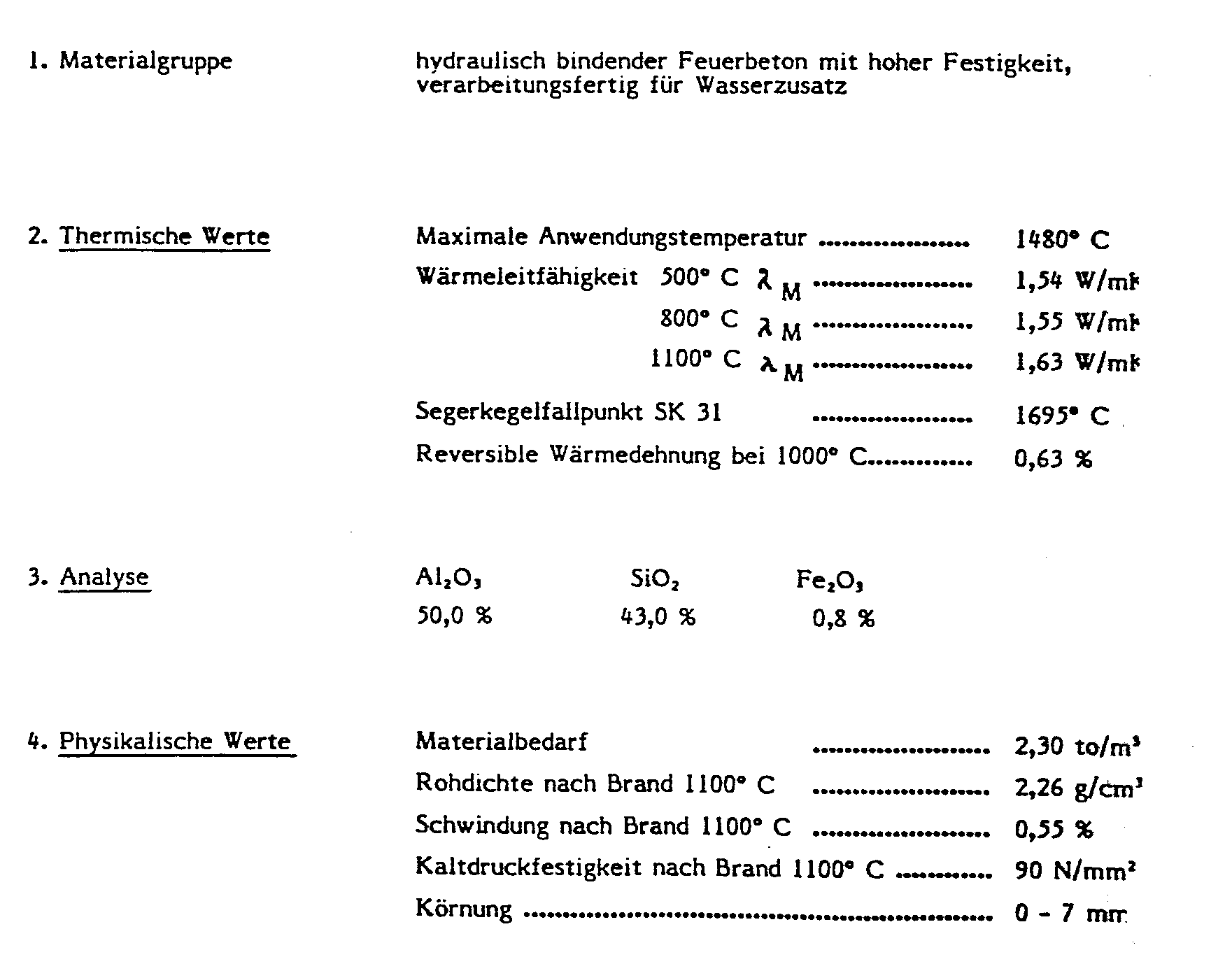
Der Erfindung liegt die Aufgabe zugrunde,die Betriebsschwierigkeiten derzeitiger metallischer Türstopfen zu vermeiden. Dazu greift die Erfindung wieder auf keramisches Material zurück, indem keramische Platten mit einer Dicke von 35 bis 120 mm verwendet werden. Es ist jedoch nicht jedes keramische Material geeignet. Vielmehr ist ein hydraulisch bindender Feuerbeton vorgesehen. Wesentliche Bestandteile dieses Feuerbetons sind Aluminiumoxid, Siliziumoxid und Eisenoxid. Vorzugsweise beträgt der Anteil an Eisenoxid (A1203) 40 - 55 %, der Anteil an Siliziumoxid (Si02) zwischen 40 und 50 %, der Anteil an Eisenoxid (Fe203) zwischen 0,5 und 1,5 %.The invention has for its object to avoid the operating difficulties of current metallic door plugs. For this purpose, the invention again uses ceramic material by using ceramic plates with a thickness of 35 to 120 mm. However, not every ceramic material is suitable. Rather, a hydraulically binding refractory concrete is provided. The essential components of this refractory concrete are aluminum oxide, silicon oxide and iron oxide. The proportion of iron oxide (A1 2 0 3 ) is preferably 40-55%, the proportion of silicon oxide (Si0 2 ) between 40 and 50%, the proportion of iron oxide (Fe 2 0 3 ) between 0.5 and 1.5% .
Je nach Art des verwendeten keramischen Materials kann sich ein Verhältnis von Dicke zur Plattenbreite von 1 : 3 bis 1 : 20 ergeben.Depending on the type of ceramic material used, a ratio of thickness to plate width of 1: 3 to 1:20 can result.
In weiterer Ausbildung der Erfindung besteht die keramische Platte aus austauschbaren Elementen. Die austauschbaren Elemente sind wahlweise übereinander angeordnet und werden jeweils in Metallrahmen gehalten. Die Metallrahmen sind einzeln befestigt, z. B. mit angeschweißten Trageisen. Das erlaubt ein einfaches und leichtes Auswechseln der keramischen Elemente im Falle einer Beschädigung.In a further embodiment of the invention, the ceramic plate consists of interchangeable elements. The interchangeable elements are optionally arranged one above the other and are each held in a metal frame. The metal frames are attached individually, e.g. B. with welded carrying iron. This allows simple and easy replacement of the ceramic elements in the event of damage.
Vorzugsweise sind die Metalltragrahmen verstellbar an der Türe befestigt. Das geschieht mittels geeigneter Trageisen bzw. Kontertrageisen,die miteinander verschraubt oder verkeilt sind. Im Falle der Verschraubung sind zur Verstellung Langlöcher vorgesehen.The metal support frames are preferably fastened to the door in an adjustable manner. This is done by means of suitable carrier iron or counter carrier, which are screwed or wedged together. In the case of screwing, elongated holes are provided for adjustment.
Das Türblatt der Koksofentür wird zweckmäßigerweise mit einer Isolierschicht versehen, die eine Aufwärmung der Tür und eine damit verknüpfte hohe Wärmeabstrahlung, d. h. Wärmeverlust und Wärmebelastung der Bedienungsleute, verhindert. Die Isolierschicht ist 50 - 100 mm dick.The door leaf of the coke oven door is expediently provided with an insulating layer, which heats up the door and the associated high heat radiation, i. H. Loss of heat and heat load on the operators are prevented. The insulation layer is 50 - 100 mm thick.
Die Keramikplatte ragt wahlweise soweit in die Ofenkammer hinein, daß die Ofenfüllung genausoweit wie mit herkömmlichen keramischen Stopfen zurückgehalten wird. Die Verstellbarkeit ermöglicht jedoch auch eine Rücknahme der keramischen Platten und eine damit verbundene Vergrößerung des Ofenraumes. Die jeweilige Stellung der keramischen Platte kann sich jedoch auch aus einer optimierten Anordnung in Bezug auf den letzten Heizzug in den Koksofenwänden ergeben.The ceramic plate protrudes into the furnace chamber to the extent that the furnace filling is retained as much as with conventional ceramic plugs. However, the adjustability also allows the ceramic plates to be taken back and the associated furnace space to be enlarged. The respective position of the Ceramic plate can also result from an optimized arrangement with respect to the last Heizzu g in the coke oven walls.
Der angestrebte große Gassammelraum entsteht bei der erfindungsgemäßen keramischen Platte hinter dem metallischen Tragrahmen, d. h. zwischen der keramischen Platte und der Isolierschicht.The desired large gas collecting space arises in the ceramic plate according to the invention behind the metallic support frame, i. H. between the ceramic plate and the insulating layer.
In der Zeichnung sind verschiedene Ausführungsbeispiele der Erfindung dargestellt.Various exemplary embodiments of the invention are shown in the drawing.
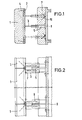
Figur 1 zeigt einen Querschnitt durch einen erfindungsgemäßen Türstopfen mit Koksofentür. Darin ist mit 1 eine keramische Platte bezeichnet, die keramische Platte ist in einem hitzbeständigen Stahlrahmen 2 mit drei angeschweißten Trageisen 3 verstellbar gehalten. Dabei sind in die keramische Frontplatte Halteanker 4 als Verbindungselemente zu dem Metallrahmen 2 eingeformt. Die Halteanker 4 sind strichpunktiert dargestellt. Im Ausführungsbeispiel ist als keramisches Material entweder vorgesehen :

Wie aus Figur 1 und 2 ersichtlich ist, ist die Koksofentür 8 mit einer Isolierschicht 7 vor übermäßiger Wärmebelastung geschützt. Die Isolierschicht 7 besteht wahlweise wieder aus keramischem Material. Bei Verwendung von keramischem Material wird dieses angeformt und vorzugsweise durch Halteanker 10 gesichert. Die Halteanker 10 sind wiederum strichpunktiert dargestellt.As can be seen from FIGS. 1 and 2, the
Zwischen der keramischen Frontplatte 1 und der Isolierschicht 7 besteht ein Gaskanal, durch den die beim Verkokungsvorgang freiwerdenden Gase, die zwischen der nicht dargestellten Koksofenwandung und der keramischen Frontplatte 1 durchtreten, in den Gassammelraum abziehen.Between the ceramic
Nach Figur 2 und 3 setzt sich ein Türstopfen aus mehreren übereinander angeordneten Frontplatten 1 zusammen. Die Trageisen 3 und Kontertrageisen 5 befinden sich jeweils oben und unten an dem zu den keramischen Frontplatten 1 gehörenden Metallrahmen. Vorteilhafterweise erlaubt das die Verwendung eines Kontertrageisens 5 zugleich für zwei einander gegenüberliegende Traqeisen 3. Ferner ist von Vorteil, für jede Frontplatte 1 bzw. mit Stahlrahmen 2 jeweils drei Befestigungstellen mit Trageisen 3 und Kontertrageisen 5 vorzusehen. Dadurch entstehen statisch bestimmte Systeme mit besonders günstigem Verhalten unter Wärmebelastung. Von den drei Befestigungsstellen ist jeweils eine auf der Mittel linie der Koksofentür angeordnet. Die beiden anderen liegen jeweils beiderseits der Mittellinie. Dies ist in Figur 3 dargestellt.According to FIGS. 2 and 3, a door stopper is composed of a plurality of
Es können aber auch vier Befestigungsstellen gewäht werden. Diese befinden sich dann an den vier Ecken der Platten. Dabei kann jedes Trageisen und Kontertrageisen die Befestigung für zwei aneinander liegender Ecken zweier benachbarter keramischer Platten bilden.It can also be four attachment points g ewäht. These are then located at the four corners of the panels. Each support iron and counter support iron can form the attachment for two adjacent corners of two adjacent ceramic plates.
Figur 4 zeigt einen Schnitt durch eine Befestigungsstelle mit zwei einander gegenüberliegenden Trageisen 3 und einem Kontertrageisen 5.FIG. 4 shows a section through a fastening point with two carrying
Zum Anheizen eines Türstopfens wird der Gaskanal zwischen Stopfen und Tür mit Mineralwolle oder dergleichen geschlossen. Diese Wolle wird nach ausreichender Erwärmung des Stopfens wieder entformt.To heat a door stopper, the gas channel between the stopper and the door is closed with mineral wool or the like. This wool is removed from the mold after it has been sufficiently heated.
Nach Figur 6 und 7 sind die Kermaikschilder mit Platten 20 versehen, die jeweils an vier Ecken befestigt sind. Als Befestigung dienen wiederum Trageisen 21 und Kontertrageisen 22, die verstellbar sind. Jedes Trageisen bildet zugleich eine Befestigung für eine darüber und eine darunter angeordnete Platte 20. Während die Befestigung an den oberen Plattenecken mit Kraft- und Formschluß erfolgt, erlaubt die Befestigung an den unteren Plattenecken eine Verschiebung in Längsschlitzen entsprechend der Wärmedehnung. Die zugehörigen Befestigungsschrauben sitzen lose. Ein vollständiges Lösen wird durch Kontermuttern verhindert.According to FIGS. 6 and 7, the ceramic signs are provided with
Um die untere Befestigung der Platten vor der Kokskohle zu schützen, sind die Platten unten bei 23 eingezogen und die Befestigungsstellen durch Kantensteine 24 abgedeckt. Die Kantensteine 24 werden gleichfalls von den Trageisen 21 gehalten.In order to protect the lower fastening of the plates from the coking coal, the plates are drawn in at 23 below and the fastening points are covered by
Claims (10)
Applications Claiming Priority (2)
| Application Number | Priority Date | Filing Date | Title |
|---|---|---|---|
| DE3447187 | 1984-12-22 | ||
| DE3447187A DE3447187A1 (en) | 1984-12-22 | 1984-12-22 | DOOR PLUG FOR COOKING DOORS |
Publications (3)
| Publication Number | Publication Date |
|---|---|
| EP0186774A2 true EP0186774A2 (en) | 1986-07-09 |
| EP0186774A3 EP0186774A3 (en) | 1987-02-04 |
| EP0186774B1 EP0186774B1 (en) | 1988-10-26 |
Family
ID=6253744
Family Applications (1)
| Application Number | Title | Priority Date | Filing Date |
|---|---|---|---|
| EP85114837A Expired EP0186774B1 (en) | 1984-12-22 | 1985-11-22 | Door plug for coke oven doors |
Country Status (7)
| Country | Link |
|---|---|
| EP (1) | EP0186774B1 (en) |
| JP (1) | JP2641094B2 (en) |
| AU (1) | AU579911B2 (en) |
| BR (1) | BR8506418A (en) |
| CA (1) | CA1270460A (en) |
| DE (2) | DE3447187A1 (en) |
| SU (1) | SU1616521A3 (en) |
Cited By (3)
| Publication number | Priority date | Publication date | Assignee | Title |
|---|---|---|---|---|
| DE3740927C1 (en) * | 1987-12-03 | 1988-12-01 | Savoie Feuerfest Gmbh Hochtemp | Door stopper for coking oven doors |
| EP0562037A1 (en) * | 1990-12-14 | 1993-09-29 | Bethlehem Steel Corporation | Method for controlling the emissions from a slot type coke oven |
| EP2762549A1 (en) * | 2013-01-30 | 2014-08-06 | Beck u. Kaltheuner Feuerfeste Erzeugnisse GmbH & Co. KG | Refractory shield plate of a coke oven door |
Families Citing this family (2)
| Publication number | Priority date | Publication date | Assignee | Title |
|---|---|---|---|---|
| DE3739452C1 (en) * | 1987-11-17 | 1988-12-22 | Otto Feuerfest Gmbh | Coke oven door with ceramic shield structure |
| DE102007058473B4 (en) | 2007-12-04 | 2009-11-26 | Uhde Gmbh | Method and device for closing a coke oven, which is loaded by a horizontally directed, front and rear oven opening or prepared for coking |
Citations (5)
| Publication number | Priority date | Publication date | Assignee | Title |
|---|---|---|---|---|
| DE456095C (en) * | 1925-04-15 | 1928-02-15 | Willi Hencke | Slide lock for oven doors |
| DE493115C (en) * | 1928-07-22 | 1930-03-04 | Stettiner Chamotte Fabrik Act | Door lock with protective shield for ovens for the production of gas and coke |
| US4086145A (en) * | 1977-03-14 | 1978-04-25 | Jones & Laughlin Steel Corporation | Coke oven door lining |
| US4217177A (en) * | 1978-12-05 | 1980-08-12 | Jones & Laughlin Steel Corporation | Vented coke oven door apparatus |
| DE3105703A1 (en) * | 1979-11-08 | 1982-06-24 | Wsw Stahl- Und Wasserbau Gmbh, 4355 Waltrop | Coking plate made up of screens |
Family Cites Families (6)
| Publication number | Priority date | Publication date | Assignee | Title |
|---|---|---|---|---|
| DE238363C (en) * | ||||
| DE489249C (en) * | 1925-05-19 | 1930-01-15 | E H Heinrich Koppers Dr Ing | Coke oven door |
| DE513594C (en) * | 1928-03-01 | 1930-11-29 | Stettiner Chamotte Fabrik Act | Closure for horizontal chamber ovens |
| JPS5243483B2 (en) * | 1973-09-04 | 1977-10-31 | ||
| DE2945017A1 (en) * | 1979-11-08 | 1981-05-21 | Ruhrkohle Ag, 4300 Essen | Coke oven door - with hollow stopper as gas collecting space for improved gas and coke quality |
| ZA82980B (en) * | 1981-02-17 | 1983-01-26 | Wsw Planungsges | Process of coking coal |
-
1984
- 1984-12-22 DE DE3447187A patent/DE3447187A1/en not_active Withdrawn
-
1985
- 1985-11-22 EP EP85114837A patent/EP0186774B1/en not_active Expired
- 1985-11-22 DE DE8585114837T patent/DE3565853D1/en not_active Expired
- 1985-12-17 AU AU51346/85A patent/AU579911B2/en not_active Ceased
- 1985-12-18 SU SU853990065A patent/SU1616521A3/en active
- 1985-12-18 JP JP60283202A patent/JP2641094B2/en not_active Expired - Lifetime
- 1985-12-20 BR BR8506418A patent/BR8506418A/en not_active IP Right Cessation
- 1985-12-20 CA CA000498235A patent/CA1270460A/en not_active Expired - Fee Related
Patent Citations (5)
| Publication number | Priority date | Publication date | Assignee | Title |
|---|---|---|---|---|
| DE456095C (en) * | 1925-04-15 | 1928-02-15 | Willi Hencke | Slide lock for oven doors |
| DE493115C (en) * | 1928-07-22 | 1930-03-04 | Stettiner Chamotte Fabrik Act | Door lock with protective shield for ovens for the production of gas and coke |
| US4086145A (en) * | 1977-03-14 | 1978-04-25 | Jones & Laughlin Steel Corporation | Coke oven door lining |
| US4217177A (en) * | 1978-12-05 | 1980-08-12 | Jones & Laughlin Steel Corporation | Vented coke oven door apparatus |
| DE3105703A1 (en) * | 1979-11-08 | 1982-06-24 | Wsw Stahl- Und Wasserbau Gmbh, 4355 Waltrop | Coking plate made up of screens |
Cited By (4)
| Publication number | Priority date | Publication date | Assignee | Title |
|---|---|---|---|---|
| DE3740927C1 (en) * | 1987-12-03 | 1988-12-01 | Savoie Feuerfest Gmbh Hochtemp | Door stopper for coking oven doors |
| EP0562037A1 (en) * | 1990-12-14 | 1993-09-29 | Bethlehem Steel Corporation | Method for controlling the emissions from a slot type coke oven |
| EP0562037A4 (en) * | 1990-12-14 | 1993-12-01 | Bethlehem Steel Corporation | Method for controlling the emissions from a slot type coke oven |
| EP2762549A1 (en) * | 2013-01-30 | 2014-08-06 | Beck u. Kaltheuner Feuerfeste Erzeugnisse GmbH & Co. KG | Refractory shield plate of a coke oven door |
Also Published As
| Publication number | Publication date |
|---|---|
| CA1270460A (en) | 1990-06-19 |
| DE3565853D1 (en) | 1988-12-01 |
| SU1616521A3 (en) | 1990-12-23 |
| BR8506418A (en) | 1986-09-02 |
| EP0186774A3 (en) | 1987-02-04 |
| JP2641094B2 (en) | 1997-08-13 |
| AU5134685A (en) | 1986-06-26 |
| JPS61155489A (en) | 1986-07-15 |
| AU579911B2 (en) | 1988-12-15 |
| EP0186774B1 (en) | 1988-10-26 |
| DE3447187A1 (en) | 1986-07-03 |
Similar Documents
| Publication | Publication Date | Title |
|---|---|---|
| EP0186774B1 (en) | Door plug for coke oven doors | |
| DE3742861C1 (en) | Metallurgical vessel | |
| DE3739452C1 (en) | Coke oven door with ceramic shield structure | |
| DE3505551C2 (en) | Coke oven door with a ceramic stopper | |
| DE2532097A1 (en) | OVEN CHAMBER LOCK FOR A COK OVEN | |
| EP0033874A2 (en) | Cooler for the dry cooling of coke | |
| DE2945017A1 (en) | Coke oven door - with hollow stopper as gas collecting space for improved gas and coke quality | |
| WO1998005451A1 (en) | Fireproof plate and a clamping device for a sliding gate at the outlet of a vessel containing molten metal | |
| EP0058320B1 (en) | Process for the coking of coal and coke oven for carrying out the process | |
| EP0023273B1 (en) | Coke oven door | |
| DE2361495B2 (en) | ARRANGEMENT FOR CLOSING A LOADING OPENING OF A COOK OVEN | |
| DE69816000T2 (en) | Device for protecting the injector tip of a burner and heating system containing the same | |
| EP0154232B1 (en) | Coke oven door with a separate shield for heat protection | |
| DE753203C (en) | Self-sealing door for horizontal coke ovens | |
| DE494151C (en) | Rotary kiln with interchangeable and air-cooled carriers | |
| EP2733225B1 (en) | Cooling element assembly | |
| DE2805924C2 (en) | Impact armor for blast furnaces | |
| DE8608319U1 (en) | Holder for ceramic plates on coke oven doors | |
| EP0084366B1 (en) | Coke oven chamber door | |
| DE2601708A1 (en) | LOCK FOR A HORIZONTAL COOK OVEN CHAMBER | |
| DE828099C (en) | Anchoring of coke ovens | |
| DE2218188B2 (en) | COOLED PUNCH DEVICE | |
| EP0680797B1 (en) | Fixing device for refractory valve plates | |
| DD130680B1 (en) | DEVICE FOR SEALING BETWEEN CHAMBER OVEN AND HERDWAGEN | |
| DE2149064A1 (en) | RUST PLATE FOR COOLING, PRE-HEATING AND BURNING GRATES |
Legal Events
| Date | Code | Title | Description |
|---|---|---|---|
| PUAI | Public reference made under article 153(3) epc to a published international application that has entered the european phase |
Free format text: ORIGINAL CODE: 0009012 |
|
| AK | Designated contracting states |
Kind code of ref document: A2 Designated state(s): BE DE FR GB IT NL |
|
| PUAL | Search report despatched |
Free format text: ORIGINAL CODE: 0009013 |
|
| AK | Designated contracting states |
Kind code of ref document: A3 Designated state(s): BE DE FR GB IT NL |
|
| 17P | Request for examination filed |
Effective date: 19870110 |
|
| 17Q | First examination report despatched |
Effective date: 19871223 |
|
| ITF | It: translation for a ep patent filed | ||
| GRAA | (expected) grant |
Free format text: ORIGINAL CODE: 0009210 |
|
| AK | Designated contracting states |
Kind code of ref document: B1 Designated state(s): BE DE FR GB IT NL |
|
| GBT | Gb: translation of ep patent filed (gb section 77(6)(a)/1977) | ||
| REF | Corresponds to: |
Ref document number: 3565853 Country of ref document: DE Date of ref document: 19881201 |
|
| ET | Fr: translation filed | ||
| PLBE | No opposition filed within time limit |
Free format text: ORIGINAL CODE: 0009261 |
|
| STAA | Information on the status of an ep patent application or granted ep patent |
Free format text: STATUS: NO OPPOSITION FILED WITHIN TIME LIMIT |
|
| 26N | No opposition filed | ||
| ITTA | It: last paid annual fee | ||
| PGFP | Annual fee paid to national office [announced via postgrant information from national office to epo] |
Ref country code: BE Payment date: 20001002 Year of fee payment: 16 |
|
| PGFP | Annual fee paid to national office [announced via postgrant information from national office to epo] |
Ref country code: GB Payment date: 20001013 Year of fee payment: 16 |
|
| PGFP | Annual fee paid to national office [announced via postgrant information from national office to epo] |
Ref country code: DE Payment date: 20001107 Year of fee payment: 16 |
|
| PGFP | Annual fee paid to national office [announced via postgrant information from national office to epo] |
Ref country code: FR Payment date: 20001115 Year of fee payment: 16 |
|
| PGFP | Annual fee paid to national office [announced via postgrant information from national office to epo] |
Ref country code: NL Payment date: 20001130 Year of fee payment: 16 |
|
| PG25 | Lapsed in a contracting state [announced via postgrant information from national office to epo] |
Ref country code: GB Free format text: LAPSE BECAUSE OF NON-PAYMENT OF DUE FEES Effective date: 20011122 |
|
| PG25 | Lapsed in a contracting state [announced via postgrant information from national office to epo] |
Ref country code: BE Free format text: LAPSE BECAUSE OF NON-PAYMENT OF DUE FEES Effective date: 20011130 |
|
| REG | Reference to a national code |
Ref country code: GB Ref legal event code: IF02 |
|
| BERE | Be: lapsed |
Owner name: RUHRKOHLE A.G. Effective date: 20011130 |
|
| PG25 | Lapsed in a contracting state [announced via postgrant information from national office to epo] |
Ref country code: NL Free format text: LAPSE BECAUSE OF NON-PAYMENT OF DUE FEES Effective date: 20020601 |
|
| PG25 | Lapsed in a contracting state [announced via postgrant information from national office to epo] |
Ref country code: DE Free format text: LAPSE BECAUSE OF NON-PAYMENT OF DUE FEES Effective date: 20020702 |
|
| GBPC | Gb: european patent ceased through non-payment of renewal fee |
Effective date: 20011122 |
|
| PG25 | Lapsed in a contracting state [announced via postgrant information from national office to epo] |
Ref country code: FR Free format text: LAPSE BECAUSE OF NON-PAYMENT OF DUE FEES Effective date: 20020730 |
|
| NLV4 | Nl: lapsed or anulled due to non-payment of the annual fee |
Effective date: 20020601 |
|
| REG | Reference to a national code |
Ref country code: FR Ref legal event code: ST |
|
| REG | Reference to a national code |
Ref country code: FR Ref legal event code: ST |