EP0186207B1 - Thermal transfer recording apparatus - Google Patents
Thermal transfer recording apparatus Download PDFInfo
- Publication number
- EP0186207B1 EP0186207B1 EP85116593A EP85116593A EP0186207B1 EP 0186207 B1 EP0186207 B1 EP 0186207B1 EP 85116593 A EP85116593 A EP 85116593A EP 85116593 A EP85116593 A EP 85116593A EP 0186207 B1 EP0186207 B1 EP 0186207B1
- Authority
- EP
- European Patent Office
- Prior art keywords
- support plate
- head
- end portion
- head support
- pressing
- Prior art date
- Legal status (The legal status is an assumption and is not a legal conclusion. Google has not performed a legal analysis and makes no representation as to the accuracy of the status listed.)
- Expired
Links
- 238000010276 construction Methods 0.000 description 3
- 230000000295 complement effect Effects 0.000 description 1
- 230000001419 dependent effect Effects 0.000 description 1
- 238000010586 diagram Methods 0.000 description 1
- 239000013013 elastic material Substances 0.000 description 1
- 238000010438 heat treatment Methods 0.000 description 1
- 238000004519 manufacturing process Methods 0.000 description 1
- 239000000155 melt Substances 0.000 description 1
Images

Classifications
-
- B—PERFORMING OPERATIONS; TRANSPORTING
- B41—PRINTING; LINING MACHINES; TYPEWRITERS; STAMPS
- B41J—TYPEWRITERS; SELECTIVE PRINTING MECHANISMS, i.e. MECHANISMS PRINTING OTHERWISE THAN FROM A FORME; CORRECTION OF TYPOGRAPHICAL ERRORS
- B41J2/00—Typewriters or selective printing mechanisms characterised by the printing or marking process for which they are designed
- B41J2/315—Typewriters or selective printing mechanisms characterised by the printing or marking process for which they are designed characterised by selective application of heat to a heat sensitive printing or impression-transfer material
- B41J2/32—Typewriters or selective printing mechanisms characterised by the printing or marking process for which they are designed characterised by selective application of heat to a heat sensitive printing or impression-transfer material using thermal heads
- B41J2/325—Typewriters or selective printing mechanisms characterised by the printing or marking process for which they are designed characterised by selective application of heat to a heat sensitive printing or impression-transfer material using thermal heads by selective transfer of ink from ink carrier, e.g. from ink ribbon or sheet
-
- B—PERFORMING OPERATIONS; TRANSPORTING
- B41—PRINTING; LINING MACHINES; TYPEWRITERS; STAMPS
- B41J—TYPEWRITERS; SELECTIVE PRINTING MECHANISMS, i.e. MECHANISMS PRINTING OTHERWISE THAN FROM A FORME; CORRECTION OF TYPOGRAPHICAL ERRORS
- B41J25/00—Actions or mechanisms not otherwise provided for
- B41J25/304—Bodily-movable mechanisms for print heads or carriages movable towards or from paper surface
- B41J25/312—Bodily-movable mechanisms for print heads or carriages movable towards or from paper surface with print pressure adjustment mechanisms, e.g. pressure-on-the paper mechanisms
Definitions
- the present invention relates to a thermal transfer recording apparatus which allows a thermal head to press on a platen roller, through ink and printing sheets interposed in between as set forth in the preamble of claim 1.
- a thermal transfer recording apparatus which allows a thermal head to press on a platen roller, through ink and printing sheets interposed in between as set forth in the preamble of claim 1.
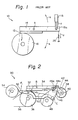
- Such apparatus is well known in the art and the principles thereof are generally shown in Fig. 1 of the drawings.
- thermal transfer recording is effected by causing an ink sheet, which is provided with an ink layer on one surface thereof, and a recording sheet into contact, then pressing a thermal head against the other surface of the ink sheet, and then applying a current to selected ones of heating resistors of the thermal head to heat the head.
- the heat of the head melts the ink on the ink sheet to transfer it to the recording sheet.
- the known apparatus 10 for such thermal transfer recording shown in Fig. 1, includes a platen roller 16, a thermal head 12, a support plate 14 adapted to support the thermal head 12 at one end thereof and pivotally movable about a fulcrum A to bring the head 12 into and out of the vicinity of the platen roller 16, and a pull-type solenoid device 18 having a plunger or drive shaft 18a, which is connected to the other end of the support plate 14 and directly reciprocated to move the support plate 14 in the above-mentioned manner.
- the head 12 is brought into the vicinity of the platen roller 16 by the pull-type solenoid device 18 (see arrow a) and driven away from the platen roller 16 by a spring 20, as shown by arrow b.
- the head fails to press on the platen roller with sufficient force F (which should generally be about 100 N) unles the support plate is dimensioned longer between the fulcrum and the head than between the fulcrum and the drive shaft of the solenoid device or a large-scale pull-type solenoid device is used. This makes the whole apparatus bulky and aggravates power consumption.
- F which should generally be about 100 N
- a preferred embodiment of the invention is subject-matter of the dependent claim.
- the apparatus generally 30, includes a thermal head 32 which is mounted on a support plate 34.
- the support plate 34 has a first portion 34a and a second portion 34b which is narrower than the first portion 34a.
- the support plate 34 is movable in a seesaw motion about a fulcrum B.
- a platen roller 36 is made of an elastic material such as rubber and located below the thermal head 32.
- a rotary solenoid 38 which accommodates a spring therein has a rotary plunger 38a to which a rotary shaft 40 is connected.
- the rotary-type solenoid device is smaller in size than the pull-type solenoid device used with the prior art apparatus and, yet produces a considerable torque which insures sufficient pressure of the head 32 with the platen roller 36.
- a first cam 42 is mounted on the rotary shaft 40, while a pin 34c extends downwardly from the other end of the support plate 34. The upper surface of the free end of the first cam 42 faces the lower end of the pin 34c.
- the pin 34c may be provided on the first cam 42 which is fixed to the rotary shaft 40, or a roller may be provided on the free end of the pin 34c which is not fixed in place.
- a pair of spaced second cams 44 are also mounted on the rotary shaft 40.
- Pins 44a are each studded in the free end of the second cam 44 and movably received in a slot 46a which is formed through flat member 46.
- a separator roller 52 is supported by one end of the flat members 46 in order to separate an ink sheet 50 which is dispensed from an ink sheet roller 48.
- the reference numeral 54 designates an ink sheet take-up roller, and 56 a recording sheet.
- a symbol C designates the center of rotation of the flat members 46.
- the slots 46a of the flat members 46 allow one to freely move the support plate 34 or the flat member 46 to thereby raise the thermal head 32 away from the platen 36 or release the roller 52 from the ink sheet 50 in the event of, for example, replacement of the ink sheet 50.
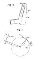
- the slots 46a each merge into a slightly enlarged portion 46b at the upper end which is complementary in configuration to the pin 44a.
- a line tangential to such a circle at the position of the pin 44a is located above the center of the rotary shaft 38a.
- the first cam 42 which is rotated by the rotary solenoid device 48 raises the adjacent end of the support plate 34 and, thereby, causes the thermal head 32 into pressing toward with the platen roller 36.
- the thermal head 32 is capable of pressing toward the platen roller 36 with a stronger force than in the prior art apparatus.
- the second cams 44 which are also mounted on the rotary shaft 40 serve as another source of pressure force which urges the head 32 against the platen roller 56 as explained infra. Specifically, while the first cam 42 is rotated to hold the head 32 in pressing against the platen roller 36, the second cams 44 are also rotated to cause the head 32 to further strongly press against the platen roller 36.
- a force F is imparted by the tension of the ink sheet 50 upwardly to the separator roller 52 which is separating the ink sheet 50.
- F i cos 8 acts on the second cams 44.
- the vector of the force F 2 which acts on the pins 44a on the second cams 44 assumes a position on a circle having a radius which is defined by a line interconnecting the centers of the pins 44a and the center of rotation C of the flat members 46 and with center at the center of rotation C, and above the center of the rotatable plunger 38a. Therefore, the force acting on the pins 44a acts on the rotary shaft 40, which is associated with the solenoid device 38, with a torque F2. x3 and in the clockwise direction as viewed in Fig. 2.
- the torque acting on the shaft 40 also acts on the first cam 42 so that the force F which the first cam 42 exerts on the head 32 toward the platen roller 36 is intensified.
- the force F In the case where the diameter of the ink sheet rolled on the take-up roller 54 is relatively small or where the tension of the ink sheet 50 is relatively weak, the force F, and, therefore, the torque developing about the center of rotation C of the flat members 46 will correspondingly be reduced to in turn reduce the pressing force of the head 32 against the platen roller 36.
- a power supply associated with the solenoid device 38 is turned off. Then, the spring which is installed in the solenoid device 38 restores the first cam 42 to its original or inoperative position via the plunger 38a and shaft 40. This causes that part of the support plate 34 which is connected with the first cam 42 to be pulled downwardly and, thereby, the other part which carries the head 32 therewith upwardly from the fulcrum B. In this manner, the thermal head 32 is rapidly moved clear of the platen roller 36.
- the present invention provides a thermal transfer recording apparatus which with an extremely simple construction allows a thermal head to be pressed strongly against a platen roller.
- the simplicity of construction translates into a low production cost.
- the whole apparatus is small size and light weight and consumes a minimum of power.
- the head is immediately released from whe platen roller to enhance stability and reliability of operation.
Landscapes
- Common Mechanisms (AREA)
- Electronic Switches (AREA)
Description
- The present invention relates to a thermal transfer recording apparatus which allows a thermal head to press on a platen roller, through ink and printing sheets interposed in between as set forth in the preamble of claim 1. Such apparatus is well known in the art and the principles thereof are generally shown in Fig. 1 of the drawings.
- In an apparatus of this kind, thermal transfer recording is effected by causing an ink sheet, which is provided with an ink layer on one surface thereof, and a recording sheet into contact, then pressing a thermal head against the other surface of the ink sheet, and then applying a current to selected ones of heating resistors of the thermal head to heat the head. The heat of the head melts the ink on the ink sheet to transfer it to the recording sheet.
- The known
apparatus 10 for such thermal transfer recording, shown in Fig. 1, includes aplaten roller 16, athermal head 12, asupport plate 14 adapted to support thethermal head 12 at one end thereof and pivotally movable about a fulcrum A to bring thehead 12 into and out of the vicinity of theplaten roller 16, and a pull-type solenoid device 18 having a plunger ordrive shaft 18a, which is connected to the other end of thesupport plate 14 and directly reciprocated to move thesupport plate 14 in the above-mentioned manner. Thehead 12 is brought into the vicinity of theplaten roller 16 by the pull-type solenoid device 18 (see arrow a) and driven away from theplaten roller 16 by aspring 20, as shown by arrow b. - As described above, movements of the head into and out of pressing contact with the platen roller with the sheets interposed in between have customarily been implemented with the pull-type solenoid mounted on one end of the head support plate, which is movable in a seesaw motion, and the spring. The problem with this prior art apparatus is that when the solenoid device is actuated to press the head against the platen roller, the spring counteracts the solenoid device, as is shown in Fig. 1 by arrows c and d. Specifically, the head fails to press on the platen roller with sufficient force F (which should generally be about 100 N) unles the support plate is dimensioned longer between the fulcrum and the head than between the fulcrum and the drive shaft of the solenoid device or a large-scale pull-type solenoid device is used. This makes the whole apparatus bulky and aggravates power consumption.
- Another problem with the prior art apparatus is that since the release of the head from the platen roller is effected by the spring which is anchored to the support plate, a substantial period of time is necessary for the head from being moved clear of the platen roller after the solenoid device is deenergized, that is, rapid release of the head is unattainable. In addition, such a slow escapement of the head away from the platen roller increases a chance of head collision with the platen roller at its protruding paper cramp.
- It is therefore an object of the present invention to provide a thermal transfer recording apparatus as set forth above which allows a thermal head to press forward a platen roller with an optimum force, rapidly.
- This object is attained by the characterizing features of claim 1. A preferred embodiment of the invention is subject-matter of the dependent claim.
- The above object, the features and advantages of the present invention will become more apparent from the following detailed description taken with the accompanying drawings.
-
- Fig. 1 is a fragmentary sectional side elevation of a prior art thermal transfer recording apparatus;
- Fig. 2 is a fragmentary side elevation of a thermal transfer recording apparatus embodying the present invention;
- Fig. 3 is a perspective view of the recording apparatus of Fig. 2;
- Fig. 4 is an enlarged view of a flat member which is included in the recording apparatus of Figs. 2 and 3 and provided with a slot; and
- Fig. 5 is a diagram representative of the operation of a second cam also included in the recording apparatus of Figs. 2 and 3.
- Referring to Figs. 2 and 3, a thermal transfer recording apparatus embodying the present invention which is free from the above-discussed drawbacks is shown. The apparatus, generally 30, includes a
thermal head 32 which is mounted on asupport plate 34. As shown in Fig. 3, thesupport plate 34 has a first portion 34a and asecond portion 34b which is narrower than the first portion 34a. Thesupport plate 34 is movable in a seesaw motion about a fulcrum B.A platen roller 36 is made of an elastic material such as rubber and located below thethermal head 32. Arotary solenoid 38 which accommodates a spring therein has arotary plunger 38a to which arotary shaft 40 is connected. The rotary-type solenoid device is smaller in size than the pull-type solenoid device used with the prior art apparatus and, yet produces a considerable torque which insures sufficient pressure of thehead 32 with theplaten roller 36. Afirst cam 42 is mounted on therotary shaft 40, while apin 34c extends downwardly from the other end of thesupport plate 34. The upper surface of the free end of thefirst cam 42 faces the lower end of thepin 34c. Alternatively, thepin 34c may be provided on thefirst cam 42 which is fixed to therotary shaft 40, or a roller may be provided on the free end of thepin 34c which is not fixed in place. A pair of spacedsecond cams 44 are also mounted on therotary shaft 40. Pins 44a are each studded in the free end of thesecond cam 44 and movably received in aslot 46a which is formed throughflat member 46. Aseparator roller 52 is supported by one end of theflat members 46 in order to separate anink sheet 50 which is dispensed from anink sheet roller 48. Thereference numeral 54 designates an ink sheet take-up roller, and 56 a recording sheet. A symbol C designates the center of rotation of theflat members 46. Theslots 46a of theflat members 46 allow one to freely move thesupport plate 34 or theflat member 46 to thereby raise thethermal head 32 away from theplaten 36 or release theroller 52 from theink sheet 50 in the event of, for example, replacement of theink sheet 50. As shown in Fig. 4, theslots 46a each merge into a slightly enlargedportion 46b at the upper end which is complementary in configuration to thepin 44a. - As shown in Fig. 5, assume a circle having a radius which is defined by a line interconnecting the center of the
pin 44a on any of thesecond cams 44 and the center of rotation C of theflat members 46, and with center at the center of rotation C. In this particular embodiment, a line tangential to such a circle at the position of thepin 44a is located above the center of therotary shaft 38a. - In operation, the
first cam 42 which is rotated by therotary solenoid device 48 raises the adjacent end of thesupport plate 34 and, thereby, causes thethermal head 32 into pressing toward with theplaten roller 36. In such a construction, even if thesupport plate 34 has the same dimensions as that of the prior art apparatus in both of its extensions at opposite sides of the center of rotation B of its own, thethermal head 32 is capable of pressing toward theplaten roller 36 with a stronger force than in the prior art apparatus. In the illustrative embodiment, thesecond cams 44 which are also mounted on therotary shaft 40 serve as another source of pressure force which urges thehead 32 against theplaten roller 56 as explained infra. Specifically, while thefirst cam 42 is rotated to hold thehead 32 in pressing against theplaten roller 36, thesecond cams 44 are also rotated to cause thehead 32 to further strongly press against theplaten roller 36. - In detail, a force F, is imparted by the tension of the
ink sheet 50 upwardly to theseparator roller 52 which is separating theink sheet 50. In this condition, as shown in Fig. 5, a torque x,Fcos 8 is developed about the center of rotation C of theflat member 46 with the result that a force F2=Xl/ X2. Ficos 8 acts on thesecond cams 44. At this instant, the vector of the force F2 which acts on thepins 44a on thesecond cams 44 assumes a position on a circle having a radius which is defined by a line interconnecting the centers of thepins 44a and the center of rotation C of theflat members 46 and with center at the center of rotation C, and above the center of therotatable plunger 38a. Therefore, the force acting on thepins 44a acts on therotary shaft 40, which is associated with thesolenoid device 38, with a torque F2. x3 and in the clockwise direction as viewed in Fig. 2. - In the above situation, the torque acting on the
shaft 40 also acts on thefirst cam 42 so that the force F which thefirst cam 42 exerts on thehead 32 toward theplaten roller 36 is intensified. In the case where the diameter of the ink sheet rolled on the take-up roller 54 is relatively small or where the tension of theink sheet 50 is relatively weak, the force F, and, therefore, the torque developing about the center of rotation C of theflat members 46 will correspondingly be reduced to in turn reduce the pressing force of thehead 32 against theplaten roller 36. - To release the
head 32 from theplaten roller 36, a power supply associated with thesolenoid device 38 is turned off. Then, the spring which is installed in thesolenoid device 38 restores thefirst cam 42 to its original or inoperative position via theplunger 38a andshaft 40. This causes that part of thesupport plate 34 which is connected with thefirst cam 42 to be pulled downwardly and, thereby, the other part which carries thehead 32 therewith upwardly from the fulcrum B. In this manner, thethermal head 32 is rapidly moved clear of theplaten roller 36. - In summary, it will be seen that the present invention provides a thermal transfer recording apparatus which with an extremely simple construction allows a thermal head to be pressed strongly against a platen roller. The simplicity of construction translates into a low production cost. The whole apparatus is small size and light weight and consumes a minimum of power. In addition, when a power supply is turned off, the head is immediately released from whe platen roller to enhance stability and reliability of operation.
Claims (2)
characterized in that said solenoid is a rotary solenoid (38) and that a pressing device (40, 42, 34c; 44, 46, 52) is connected to said rotary solenoid (38) for pressing the thermal head (32) against the platen roller (36) by transmitting the drive force generated by said rotary solenoid (38) to the head support plate (34), said pressing device comprising:
Applications Claiming Priority (4)
| Application Number | Priority Date | Filing Date | Title |
|---|---|---|---|
| JP196618/84U | 1984-12-28 | ||
| JP27456684A JPS61154951A (en) | 1984-12-28 | 1984-12-28 | Recording apparatus |
| JP274566/84 | 1984-12-28 | ||
| JP19661884U JPS61112957U (en) | 1984-12-28 | 1984-12-28 |
Publications (2)
| Publication Number | Publication Date |
|---|---|
| EP0186207A1 EP0186207A1 (en) | 1986-07-02 |
| EP0186207B1 true EP0186207B1 (en) | 1989-05-24 |
Family
ID=26509858
Family Applications (1)
| Application Number | Title | Priority Date | Filing Date |
|---|---|---|---|
| EP85116593A Expired EP0186207B1 (en) | 1984-12-28 | 1985-12-27 | Thermal transfer recording apparatus |
Country Status (3)
| Country | Link |
|---|---|
| US (1) | US4641151A (en) |
| EP (1) | EP0186207B1 (en) |
| DE (2) | DE186207T1 (en) |
Families Citing this family (12)
| Publication number | Priority date | Publication date | Assignee | Title |
|---|---|---|---|---|
| JPH07108591B2 (en) * | 1986-06-20 | 1995-11-22 | ソニー株式会社 | Printer |
| US5072238A (en) * | 1988-03-30 | 1991-12-10 | Canon Kabushiki Kaisha | Heat transfer recording method |
| JPH02145375A (en) * | 1988-11-28 | 1990-06-04 | Sony Corp | Thermal printer |
| DE69230957T2 (en) * | 1991-05-24 | 2000-11-30 | Mitsubishi Denki K.K., Tokio/Tokyo | Paper feed device for printing device |
| US5921687A (en) * | 1991-05-24 | 1999-07-13 | Mitsubishi Denki Kabushiki Kaisha | Printing apparatus |
| ES2099106T3 (en) * | 1991-06-20 | 1997-05-16 | Scheidt & Bachmann Gmbh | THERMAL PRINTER. |
| DE4332627A1 (en) * | 1993-09-24 | 1995-03-30 | Esselte Meto Int Gmbh | Thermal print head holder |
| GB9422707D0 (en) * | 1994-11-10 | 1995-01-04 | Open Date Equipment Ltd | Printing apparatus |
| US8153166B2 (en) * | 2006-06-08 | 2012-04-10 | Chih-Hsiung Lin | Composition for prophylaxis or treatment of urinary system infection and method thereof |
| JP4252106B1 (en) * | 2008-02-20 | 2009-04-08 | 株式会社サトー知識財産研究所 | Thermal printer |
| JP2011062898A (en) * | 2009-09-16 | 2011-03-31 | Toshiba Tec Corp | Head mechanism and printer |
| JP2011110917A (en) * | 2009-11-30 | 2011-06-09 | Seiko Instruments Inc | Thermal printer |
Family Cites Families (3)
| Publication number | Priority date | Publication date | Assignee | Title |
|---|---|---|---|---|
| JPS49106731A (en) * | 1973-02-12 | 1974-10-09 | ||
| US4639744A (en) * | 1982-12-01 | 1987-01-27 | Canon Kabushiki Kaisha | Recording apparatus |
| US4531132A (en) * | 1983-10-27 | 1985-07-23 | Ncr Corporation | Method and apparatus for thermally printing data in special fonts on documents like checks |
-
1985
- 1985-12-26 US US06/813,440 patent/US4641151A/en not_active Expired - Fee Related
- 1985-12-27 DE DE198585116593T patent/DE186207T1/en active Pending
- 1985-12-27 EP EP85116593A patent/EP0186207B1/en not_active Expired
- 1985-12-27 DE DE8585116593T patent/DE3570398D1/en not_active Expired
Also Published As
| Publication number | Publication date |
|---|---|
| EP0186207A1 (en) | 1986-07-02 |
| DE186207T1 (en) | 1986-11-27 |
| US4641151A (en) | 1987-02-03 |
| DE3570398D1 (en) | 1989-06-29 |
Similar Documents
| Publication | Publication Date | Title |
|---|---|---|
| US4641151A (en) | Thermal transfer recording apparatus | |
| US3286806A (en) | Rotatable and tiltable type head control apparatus | |
| EP0794062A1 (en) | Thermal line printer | |
| US4398461A (en) | Small printer | |
| JPS62149471A (en) | thermal printer | |
| JPS63135271A (en) | Line thermal printer | |
| US4861174A (en) | Device for driving print member of printer | |
| JPS60154090A (en) | Printing apparatus | |
| JP3764018B2 (en) | Printer paper feed mechanism | |
| JPS60165281A (en) | Heat transfer printer | |
| JPH0541022Y2 (en) | ||
| JP2531761B2 (en) | Contact / separation drive mechanism for thermal head | |
| JP3332453B2 (en) | Recording device | |
| JP2905632B2 (en) | Thermal printer | |
| JP2531352Y2 (en) | Printer drive mechanism | |
| JPH0727308B2 (en) | Pressurizing device | |
| JPH0438593B2 (en) | ||
| JP3661333B2 (en) | Printing device | |
| JPS6210142Y2 (en) | ||
| JPH01150566A (en) | Printing apparatus | |
| JPS61274974A (en) | Retraction of thermal head | |
| JPH0773938B2 (en) | Printer | |
| JPS63443Y2 (en) | ||
| JPS57163589A (en) | Paper feeder for thermal printer | |
| KR920007338Y1 (en) | Recording paper holding device for video color printer |
Legal Events
| Date | Code | Title | Description |
|---|---|---|---|
| PUAI | Public reference made under article 153(3) epc to a published international application that has entered the european phase |
Free format text: ORIGINAL CODE: 0009012 |
|
| AK | Designated contracting states |
Kind code of ref document: A1 Designated state(s): DE FR GB |
|
| EL | Fr: translation of claims filed | ||
| DET | De: translation of patent claims | ||
| 17P | Request for examination filed |
Effective date: 19861112 |
|
| 17Q | First examination report despatched |
Effective date: 19880302 |
|
| GRAA | (expected) grant |
Free format text: ORIGINAL CODE: 0009210 |
|
| AK | Designated contracting states |
Kind code of ref document: B1 Designated state(s): DE FR GB |
|
| REF | Corresponds to: |
Ref document number: 3570398 Country of ref document: DE Date of ref document: 19890629 |
|
| ET | Fr: translation filed | ||
| PLBE | No opposition filed within time limit |
Free format text: ORIGINAL CODE: 0009261 |
|
| STAA | Information on the status of an ep patent application or granted ep patent |
Free format text: STATUS: NO OPPOSITION FILED WITHIN TIME LIMIT |
|
| 26N | No opposition filed | ||
| PGFP | Annual fee paid to national office [announced via postgrant information from national office to epo] |
Ref country code: FR Payment date: 19931209 Year of fee payment: 9 |
|
| PGFP | Annual fee paid to national office [announced via postgrant information from national office to epo] |
Ref country code: GB Payment date: 19931217 Year of fee payment: 9 |
|
| PGFP | Annual fee paid to national office [announced via postgrant information from national office to epo] |
Ref country code: DE Payment date: 19931227 Year of fee payment: 9 |
|
| PG25 | Lapsed in a contracting state [announced via postgrant information from national office to epo] |
Ref country code: GB Effective date: 19941227 |
|
| GBPC | Gb: european patent ceased through non-payment of renewal fee |
Effective date: 19941227 |
|
| PG25 | Lapsed in a contracting state [announced via postgrant information from national office to epo] |
Ref country code: FR Effective date: 19950831 |
|
| PG25 | Lapsed in a contracting state [announced via postgrant information from national office to epo] |
Ref country code: DE Effective date: 19950901 |
|
| REG | Reference to a national code |
Ref country code: FR Ref legal event code: ST |