EP0186204A2 - Zinc-bromine battery - Google Patents
Zinc-bromine battery Download PDFInfo
- Publication number
- EP0186204A2 EP0186204A2 EP85116588A EP85116588A EP0186204A2 EP 0186204 A2 EP0186204 A2 EP 0186204A2 EP 85116588 A EP85116588 A EP 85116588A EP 85116588 A EP85116588 A EP 85116588A EP 0186204 A2 EP0186204 A2 EP 0186204A2
- Authority
- EP
- European Patent Office
- Prior art keywords
- electrolyte
- zinc
- bromine
- catholyte
- storage tank
- Prior art date
- Legal status (The legal status is an assumption and is not a legal conclusion. Google has not performed a legal analysis and makes no representation as to the accuracy of the status listed.)
- Granted
Links
Images

Classifications
-
- H—ELECTRICITY
- H01—ELECTRIC ELEMENTS
- H01M—PROCESSES OR MEANS, e.g. BATTERIES, FOR THE DIRECT CONVERSION OF CHEMICAL ENERGY INTO ELECTRICAL ENERGY
- H01M10/00—Secondary cells; Manufacture thereof
- H01M10/36—Accumulators not provided for in groups H01M10/05-H01M10/34
- H01M10/365—Zinc-halogen accumulators
-
- H—ELECTRICITY
- H01—ELECTRIC ELEMENTS
- H01M—PROCESSES OR MEANS, e.g. BATTERIES, FOR THE DIRECT CONVERSION OF CHEMICAL ENERGY INTO ELECTRICAL ENERGY
- H01M10/00—Secondary cells; Manufacture thereof
- H01M10/42—Methods or arrangements for servicing or maintenance of secondary cells or secondary half-cells
- H01M10/4214—Arrangements for moving electrodes or electrolyte
-
- Y—GENERAL TAGGING OF NEW TECHNOLOGICAL DEVELOPMENTS; GENERAL TAGGING OF CROSS-SECTIONAL TECHNOLOGIES SPANNING OVER SEVERAL SECTIONS OF THE IPC; TECHNICAL SUBJECTS COVERED BY FORMER USPC CROSS-REFERENCE ART COLLECTIONS [XRACs] AND DIGESTS
- Y02—TECHNOLOGIES OR APPLICATIONS FOR MITIGATION OR ADAPTATION AGAINST CLIMATE CHANGE
- Y02E—REDUCTION OF GREENHOUSE GAS [GHG] EMISSIONS, RELATED TO ENERGY GENERATION, TRANSMISSION OR DISTRIBUTION
- Y02E60/00—Enabling technologies; Technologies with a potential or indirect contribution to GHG emissions mitigation
- Y02E60/10—Energy storage using batteries
Definitions
- This invention relates to a zinc-bromine battery, and more particularly, to improvements of an electrolyte circulation type zinc-bromine battery having electrolyte storage tanks.
- a zinc-bromine battery is known as a new type of battery.
- the following fundamental electrochemical reactions take place in a reaction tank provided with an anode and a cathode of a zinc- bromine battery.
- the reaction at the cathode is:
- the reaction at the anode is:
- the cell reaction is:
- the concentration of the bromine Br 2 in the electrolyte which is produced during charge increases as the charging time passes, and the bromine Br 2 gradually diffuses toward the anode.
- the bromine Br 2 reacts with the zinc Zn at the anode, and becomes zinc ion Zn and bromine ion Br , thereby occuring self-discharge.
- the zinc-bromine battery is therefore provided with a separator membrane which zinc ion Zn 2+ and bromine ion Br can permeate but which impedes the permeation of bromine Br 2 in order to separate the reaction tank into anode and cathode reaction tanks, thereby preventing bromine Br 2 from diffusing from the cathode side to the anode side.
- a complexing agent is added to the electrolyte of the zinc-bromine battery, so that the bromine Br 2 dissolved into the electrolyte on the cathode side is converted into a complex compound which is insoluble in the electrolyte, and is deposited and precipitated in the form of oil in the electrolyte.
- zinc-bromide (ZnBr 2 ) aqueous solution is used as the electrolyte 16, and an electric conductance improver, a bromine complexing agent, a dendrite inhibiter and the like are added thereto as occasion demands.
- the charging reaction shown in the formulae (1) takes place in the reaction tank 10, and bromine Br 2 is generated on the cathode side 12 and dissolves into the electrolyte 16, while on the anode side 14 zinc Zn is deposited and a precipitation chamber 18 is formed on the anode 14.
- the reaction tank 10 in which these electrochemical reactions take place is provided with a separator membrane 20 which divides the interior of the tank into a cathode reaction tank 10a and an anode reaction tank 10b so as to prevent any occurrence of self-discharge caused by the bromine Br 2 which is produced during charge.
- the separator membrane allows the electrolyte 16 to permeate therethorugh but impedes the permeation of the bromine Br 2 which is in solution in the electrolyte 16, so as to prevent any occurrence of self-discharge.
- An ion-exchange membrane or a microporous membrane is generally used as the separator membrane 20, but a microporous membrane is more preferable from the viewpoint of reducing the inner resistance of the battery.
- an cathode electrolyte storage tank 22 and ananode electrolyte storage tank 24 are provided in order to store the energy obtained by the electrolysis reaction during charge.
- Pipes 26 and 28 provided between the cathode electrolyte storage tank 22 and the cathode reaction tank 10a constitute an electrolyte circulation passage, and a pump 30 provided in the circulation passage delivers the cathode electrolyte 16a which has reacted in the cathode reaction tank 10a to the storage tank 22, and supplies new electrolyte 16a from the storage tank 22 to the reaction tank 10a.
- the complex compound storing chamber 32 is connected to the pipe 28 by a complex compound supply pipe 36 having a valve 34.
- This valve 34 delivers the complex compound which has precipitated in the complex compound storing chamber 32 to the reaction tank 10a through the pipe 28 for the purpose of discharge.
- pipes 38 and 40 provided between the anolyte storage tank 24 and the anode reaction tank 10b constitute an electrolyte circulation passage, and a pump 42 provided in the circulation passage delivers the anolyte 16b which has reacted in the anode reaction tank 10b to the storage tank 24, and supplies new electrolyte 16b from the storage tank 24 to the reaction tank lOb..
- this zinc-bromine battery can adequately store the electrolyte 16 in the storage tanks 22 and 24, cause the charging reaction shown in the formulae (1) in the stored electrolyte 16 during charge, store the bromine complex compound in the complex compound storing chamber 32, and form the zinc precipitation chamber 13 on the anode 14, thereby storing electric power.
- the zinc-bromine battery can deliver the bromine complex compound stored in the complex compound storing chamber 32 to the cathode reaction tank 10a, and cause the discharge reaction shown in the formulae (1) between the complex compound and the zinc precipitation chamber 18 formec on the anode 14, thereby emitting the charged electric power.
- This kind of conventional zinc-bromine battery is completely divided into the cathode side and the anode side, and the catholyte 16a and the anol y te 16b are mixed with each other solely by permeation through the separator membrane 20. Since the separator membrane 20 has a predetermined resistance when the electrolyte 16 permeates it, it is impossible to store electric power by efficiently utilizing the zinc ion Zn 2+ which is contained in the catholyte during charge. It is also impossible to effectively utilize the complexing agent contained in the anol yt e 16b when a bromine complexing agent is contained in the electrolyte 16.
- Fiq. 4 shows the change in zinc ion concentration of the catholyte 16a and the anolvte 16b durinq charge.
- Fig. 5 shows the zinc ion concentration when KC1 is added to the electrolyte 16
- the difference in concentration of the zinc ions contained in the electrolytes 16a and 16b is greater in this case than the difference shown in Fig. 4, and it will be understood that the utilization ratio of the zinc ions is thereby further lowered.
- bromine Br 2 produced in the catholyte 16a during charge reacts with the bromine complexing agent and a bromine complex compound is formed.
- concentration of the complexing agent contained in the catholyte 16a is lowered.
- the utilization ratio of the bromine complexing agent contained in the anolyte 16b is low for a similar reason to that in the case of the zinc ions described above, and there has been a demand for effective countermeasures.
- a zinc-bromine battery according to the present invention is composed of an anode reaction tank and a cathode reaction tank which are separated from each other by a separator membrane for preventing self-discharge; and an electrolyte storage tank for storing an electrolyte with a bromine complexing agent added thereto; whreein an catholyte and a anolyte are circulated independently between the electrolyte storage tank and the respective reaction tanks.
- the present invention is characterized in that the catholytes and anolytes are mixed in the storage tank for the purpose of removing any difference in zinc ion concentration.
- the method of mixing the electrolytes according to the present invention includes a first method in which the electrolyte is resupplied as the catholyte and the anolyte, and thereby the bromine complex compound contained in the catholyte is precipitated and stored in the electrolyte mixing chamber.
- the above-described structure of a zinc-bromine battery according to the present invention enables the catholyte and the anolyte which have finished a predetermined electrochemical reaction in the respective reaction tank to be stirred with each other and the stirred electrolytes to be resupplied as the catholyte and the anolyte to the respective reaction tanks.
- the bromine generated-on the cathode side during charge is complexed by the complexing agent, and this complex compound flows into the electrolyte mixing chamber of the electrolyte storage tank together with the anolyte.
- the complex compound which has flowed into the electrolyte mixing chamber in this way is separated from the anolyte in the electrolyte mixing chamber by the perforated membrane provided in the storage tank, and is stored in the electrolyte mixing chamber on the upstream side of the perforated membrane.
- the present invention it is possible to equalize the zinc ion concentration of the anolyte to that of the catholyte without increasing the concentration of bromine and its complex compound, and to enhance the charging capacity by efficiently utilizing the zinc ions contained in the electrolytes, thereby improving the charging efficiency.
- the complex compound stored on the upstream side of the perforated membrane is supplied to the catholyte through the supply pipe and the electrolyte which is mixed with the bromine complex compound is thereby supplied to the cathode reaction tank.
- the complex compound supplied to the cathode side in this way and the zinc deposited on the surface of the anode.
- a conventional zinc-bromine battery has two separate electrolyte storage tanks, namely, a catholyte storage tank and ananolyte storage tank
- this embodiment includes only one electrolyte storage tank 50.
- the electrolyte storage tank 50 is divided into an electrolyte mixing chamber 54 and an electrolyte supply chamber 56 by a perforated membrane 52 provided with a multiplicity of minute holes which allows the electrolyte 16 to permeate therethrough but which impedes the permeation of bromine and its complex compound.
- the size of the minute hole which is formed on the perforated membrane 52 is small enough to impede the permeation of bromine and its complex compound.
- a polyethylene film, a polypropylene film, or a thin film of such kind is preferable as the perforated membrane.
- the mixing chamber 54 within the electrolyte storage tank 50 is provided with inlets 58 and 60 for receiving the catholyte 16a delivered from the cathode reaction tank 10a and the anolyte 16b delivered from the anode reaction tank 10b, respectively.
- the supply chamber 56 of the electrolyte storage tank 5 0 is provided with outlets 62 and 64 for supplying the catholyte 16a and the anolyte 16b to the cathode reaction tank 10a and the anode reaction tank 10b, respectively.
- the catholyte 16a and the anolyte 16b which flow from the respective reaction tanks 10a and 10b flow into the mixing chamber 54 and are stirred therein.
- the stirred electrolyte 16 permeates the perforated membrane 52 and flows into the electrolyte supply chamber 56, in which it is separated again into the catholyte 16a and the anolyte 16b, and the electrolytes 16a and 16b are supplied from the outlets 62 and 64 to the cathode reaction tank 10a and the anode reaction tank 10b, respectively.
- the bromine complex compound contained in the electrolyte 16a which has flowed into the mixing chamber 54 is separated when the electrolyte 16 permeates the perforated membrane 52, and precipitates at the bottom of the mixing chamber 54 as the complex compound chamber 32. Therefore, the electrolyte 16 which flows into the supply chamber 56 includes no complex compound.
- a complex compound supply pipe 36 is provided between the complex compound chamber 32 which is situated on the upstream side of the perforated membrane 52 and the pipe 28 which constitutes the passage for the catholyte supplied from the supply chamber 56 to the cathode reaction tank 10a.
- the complex compound which has precipitated and is stored in the complex compound chamber 32 is mixed into the catholyte 16a through this supply pipe 52.
- Fig. 2 which shows a second embodiment of the present invention
- the perforated membrane 52 is so arranged that the electrolyte 16 permeates it upwardly from the underside thereof in the electrolyte storage tank 50.
- the electrolyte storage chamber 50 in this embodiment is provided with a partition wall 70 at the central portion of the bottom surface.
- the partition wall 70 substantially divides the tank into two chambers with the upper ends thereof open.
- the perforated membrane 52 is horizontally disposed between the upper end of the partition wall and the inner wall of the electrolyte storage tank 50, whereby the electrolyte storage tank 50 is divided into the electrolyte mixing chamber 54 and the electrolyte supply chamber 56.
- the inlet 58 for the catholyte delivered through the pipe 26 is provided on one side at the lower portion of the side wall of the the electrolyte mixing chamber 54, while the inlet 60 for the anolyte delivered through the pipe 38 is provided on one side at the central portion of the side wall thereof.
- a guide wall 72 is provided on the inner top wall of the supply chamber 56 in parallel to and in opposition to the partition wall 70.
- the guide wall 72 together with the partition wall 70 defines a guide passage 74 for downwardly introducing the electrolyte 16 which contains a small amount of bromine and its complex compound and which has permeated the perforated membrane 52.
- the outlet 62 for supplying the electrolyte to the pipe 20 on the cathode side is provided at the bottom of the supply chamber 56 such as to communicate with the guide passage 74.
- outlet 40 for supplying the electrolyte to the pipe 40 on the anode side is downwardly provided at the upper portion of the supply chamber 64.
- the bromine complex compound contained in the electrolyte 16 which has flowed into the mixing chamber 54 is considerably separated when the electrolyte 16 permeates the perforated membrane 52.
- the small amount of complex compound which has permeated the perforated membrane 52 drops under the weight of its own gravity when the electrolyte 16 flows downwardly through the guide passage 74, and is supplied together with the catholyte 16a from the outlet 62 to the cathode reaction tank 10a.
- the remaining complex compound which is still contained in the electrolyte 16 drops under the weight of its own gravity when the electrolyte 16 moves upwardly toward the outlet 64, as is indicated with the arrows in Fig. 2, thereby being separated from the electrolyte 16.
- the complexing agent in the anolyte which conventionallly has hardly been utilized at all can be efficiently utilized in this embodiment. Accordingly it is possible to reduce the amount of complexing agent which needs to be added.
- the increase in pH of the electrolyte is caused by H 2 - gas which is generated when the electrolyzed zinc naturally dissolves into the electrolyte, or when self-discharge is generated, mainly on the anode side.
- the pH of the anode side shows a tendency to increase in comparison with that of the cathode side in the prior art. In this embodiment, however, since the catholyte and anolyte are completely mixed, the rise in pH of the anolyte is controlled.
Landscapes
- Engineering & Computer Science (AREA)
- Manufacturing & Machinery (AREA)
- Chemical & Material Sciences (AREA)
- Chemical Kinetics & Catalysis (AREA)
- Electrochemistry (AREA)
- General Chemical & Material Sciences (AREA)
- Hybrid Cells (AREA)
- Primary Cells (AREA)
- Secondary Cells (AREA)
- Organic Low-Molecular-Weight Compounds And Preparation Thereof (AREA)
Abstract
Description
- This invention relates to a zinc-bromine battery, and more particularly, to improvements of an electrolyte circulation type zinc-bromine battery having electrolyte storage tanks.
- A zinc-bromine battery is known as a new type of battery. The following fundamental electrochemical reactions take place in a reaction tank provided with an anode and a cathode of a zinc- bromine battery.
- The reaction at the cathode is:

- The reaction at the anode is:

- The cell reaction is:

- As is clear from the reaction formulae, zinc Zn is deposited during charge and bromine Br2 which dissolves into the electrolyte is produced at the cathode. On the other hand, during discharge the zinc Zn deposited onto the anode is oxidized to Zn 2+ and dissolves into the electrolyte, while the bromine Br2 in the electrolyte is reduced to bromine ion 2Br and dissolves into the electrolyte.
- In such a zinc-bromine battery, the concentration of the bromine Br2 in the electrolyte which is produced during charge increases as the charging time passes, and the bromine Br2 gradually diffuses toward the anode. The bromine Br2 reacts with the zinc Zn at the anode, and becomes zinc ion Zn and bromine ion Br , thereby occuring self-discharge. The zinc-bromine battery is therefore provided with a separator membrane which zinc ion Zn2+ and bromine ion Br can permeate but which impedes the permeation of bromine Br2 in order to separate the reaction tank into anode and cathode reaction tanks, thereby preventing bromine Br2 from diffusing from the cathode side to the anode side.
- Furthermore, in order to prevent diffusion of the bromine Br2, a complexing agent is added to the electrolyte of the zinc-bromine battery, so that the bromine Br2 dissolved into the electrolyte on the cathode side is converted into a complex compound which is insoluble in the electrolyte, and is deposited and precipitated in the form of oil in the electrolyte.
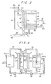
- Fig. 3 shows a conventional zinc-bromine battery produced on the basis of the above-described principle. In this battery, a.
cathode 12 and ananode 14 are provided within areaction tank 10, one on each side thereof, whereby the electrochemical reactions indicated by the formulae (1) take place between thecathode 12 andanode 14 throughelectrolytes 16. - In such a zinc-bromine battery, zinc-bromide (ZnBr2) aqueous solution is used as the
electrolyte 16, and an electric conductance improver, a bromine complexing agent, a dendrite inhibiter and the like are added thereto as occasion demands. - During charge, the charging reaction shown in the formulae (1) takes place in the
reaction tank 10, and bromine Br2 is generated on thecathode side 12 and dissolves into theelectrolyte 16, while on theanode side 14 zinc Zn is deposited and aprecipitation chamber 18 is formed on theanode 14. - On the other hand, the reaction which is reverse to the charging reaction takes place during discharge. Bromine Br2 is reduced to bromine ion 2Br on the
cathode side 12 and dissolves into theelectrolyte 16, while on theanode side 14 thezinc precipitation chamber 18 is oxidized to zinc ion zn2+, and dissolves into theelectrolyte 16. - The
reaction tank 10 in which these electrochemical reactions take place is provided with aseparator membrane 20 which divides the interior of the tank into acathode reaction tank 10a and an anode reaction tank 10b so as to prevent any occurrence of self-discharge caused by the bromine Br2 which is produced during charge. - The separator membrane allows the
electrolyte 16 to permeate therethorugh but impedes the permeation of the bromine Br2 which is in solution in theelectrolyte 16, so as to prevent any occurrence of self-discharge. An ion-exchange membrane or a microporous membrane is generally used as theseparator membrane 20, but a microporous membrane is more preferable from the viewpoint of reducing the inner resistance of the battery. - In an electrolyte circulation type battery, an cathode
electrolyte storage tank 22 and ananodeelectrolyte storage tank 24 are provided in order to store the energy obtained by the electrolysis reaction during charge. -
Pipes electrolyte storage tank 22 and thecathode reaction tank 10a constitute an electrolyte circulation passage, and apump 30 provided in the circulation passage delivers thecathode electrolyte 16a which has reacted in thecathode reaction tank 10a to thestorage tank 22, and suppliesnew electrolyte 16a from thestorage tank 22 to thereaction tank 10a. - Since a bromine complexing agent is added to the
electrolyte 16a, the bromine Br2 generated during the charge is-complexed, and is deposited as a complex compound which is insoluble in theelectrolyte 16. This complex compound is subsequently precipitated and stored at the bottom of thestorage tank 22 as a complexcompound storing chamber 32, as is shown in the battery of Fig. 3. - The complex
compound storing chamber 32 is connected to thepipe 28 by a complexcompound supply pipe 36 having avalve 34. Thisvalve 34 delivers the complex compound which has precipitated in the complexcompound storing chamber 32 to thereaction tank 10a through thepipe 28 for the purpose of discharge. - Similarly,
pipes anolyte storage tank 24 and the anode reaction tank 10b constitute an electrolyte circulation passage, and apump 42 provided in the circulation passage delivers theanolyte 16b which has reacted in the anode reaction tank 10b to thestorage tank 24, and suppliesnew electrolyte 16b from thestorage tank 24 to the reaction tank lOb.. - In this way, this zinc-bromine battery can adequately store the
electrolyte 16 in thestorage tanks electrolyte 16 during charge, store the bromine complex compound in the complexcompound storing chamber 32, and form the zinc precipitation chamber 13 on theanode 14, thereby storing electric power. During discharge, on the other hand, the zinc-bromine battery can deliver the bromine complex compound stored in the complexcompound storing chamber 32 to thecathode reaction tank 10a, and cause the discharge reaction shown in the formulae (1) between the complex compound and thezinc precipitation chamber 18 formec on theanode 14, thereby emitting the charged electric power. - Although a conventional zinc-bromine battery is capable of efficient charging and discharging in this way, it has the following problems which remain unsolved.
- This kind of conventional zinc-bromine battery is completely divided into the cathode side and the anode side, and the
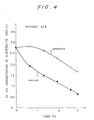
catholyte 16a and the anolyte 16b are mixed with each other solely by permeation through theseparator membrane 20. Since theseparator membrane 20 has a predetermined resistance when theelectrolyte 16 permeates it, it is impossible to store electric power by efficiently utilizing the zinc ion Zn2+ which is contained in the catholyte during charge. It is also impossible to effectively utilize the complexing agent contained in the anolyt e 16b when a bromine complexing agent is contained in theelectrolyte 16. - Fiq. 4 shows the change in zinc ion concentration of the
catholyte 16a and theanolvte 16b durinq charge. - As is obvious from the above-described reaction formulae, during charge the zinc ions Zn2+ are attracted to the
anode 14 and zinc Zn is deposited. - At this time, since the cathode side is separated from the anode side by the
separator membrane 20, it is much more difficult for the zinc ions Zn2+ in thecatholvte 16a to move toward theanode 14 than the zinc ions in theanolyte 16b. Therefore, since the zinc ions in theanolyte 16b are consumed sooner than the zinc ions Zn2+ in thecatholyte 16a and charging is completed at that point, it is impossible to perform charging by adequately utilizing the zinc ions contained in thecatholyte 16a. - In particular, when a salt halogenide such as KC1 is added to the
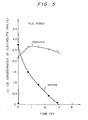
electrolyte 16 as an auxiliary electrolyte, or when an electrolyte of high concentration (more than 3 Mol/L ZnBr2) is used in order to improve the electric conductance of theelectrolyte 16, the difference in concentration of theelectrolytes anolyte 16b are reduced to an extreme extent in comparison with those of thecatholyte 16a, and the utilization ratio of the zinc ions contained in theelectrolyte 16 is further lowered. - Fig. 5 shows the zinc ion concentration when KC1 is added to the
electrolyte 16, As is clear from the graph, the difference in concentration of the zinc ions contained in theelectrolytes - This is because the KCl added to the
electrolyte 16 in this way reacts with the zinc ion Zn 2+ and becomes (ZnCl4)2-, so that some of the zinc ions which should intrinsically be plus become minus ions and are attracted toward the cathode side, thereby substantially lowering the concentration of the zinc ions contained in theelectrolyte 16b. - In addition, the bromine Br2 produced in the
catholyte 16a during charge reacts with the bromine complexing agent and a bromine complex compound is formed. With the increase in amount of bromine complex compound, the concentration of the complexing agent contained in thecatholyte 16a is lowered. - However, the utilization ratio of the bromine complexing agent contained in the
anolyte 16b is low for a similar reason to that in the case of the zinc ions described above, and there has been a demand for effective countermeasures. - Accordingly, it is an object of the present invention to provide a zinc-bromine battery which is capable of reducing the difference in zinc ion concentration as between the catholyte and the anolyte, improving the utilization ratio of the zinc ions contained in the electrolyte, and increasing the charged electric energy.
- To achieve this aim, a zinc-bromine battery according to the present invention is composed of an anode reaction tank and a cathode reaction tank which are separated from each other by a separator membrane for preventing self-discharge; and an electrolyte storage tank for storing an electrolyte with a bromine complexing agent added thereto; whreein an catholyte and a anolyte are circulated independently between the electrolyte storage tank and the respective reaction tanks.
- The present invention is characterized in that the catholytes and anolytes are mixed in the storage tank for the purpose of removing any difference in zinc ion concentration.
- The method of mixing the electrolytes according to the present invention includes a first method in which the electrolyte is resupplied as the catholyte and the anolyte, and thereby the bromine complex compound contained in the catholyte is precipitated and stored in the electrolyte mixing chamber.
- A supply pipe is provided between the complex compound storing chamber and a passage for the catholyte supplied from the electrolyte supply chamber.
- The above-described structure of a zinc-bromine battery according to the present invention enables the catholyte and the anolyte which have finished a predetermined electrochemical reaction in the respective reaction tank to be stirred with each other and the stirred electrolytes to be resupplied as the catholyte and the anolyte to the respective reaction tanks.
- The bromine generated-on the cathode side during charge is complexed by the complexing agent, and this complex compound flows into the electrolyte mixing chamber of the electrolyte storage tank together with the anolyte.
- However, the complex compound which has flowed into the electrolyte mixing chamber in this way is separated from the anolyte in the electrolyte mixing chamber by the perforated membrane provided in the storage tank, and is stored in the electrolyte mixing chamber on the upstream side of the perforated membrane.
- Accordingly, no difference in concentration of zinc ions and bromine complexing agent is seen between the catholyte and the anolyte during charge of the zinc-bromine battery according to the present invention.
- Therefore, according to the present invention, it is possible to equalize the zinc ion concentration of the anolyte to that of the catholyte without increasing the concentration of bromine and its complex compound, and to enhance the charging capacity by efficiently utilizing the zinc ions contained in the electrolytes, thereby improving the charging efficiency.
- It is also possible to equalize the concentration of the complexing agent contained in the catholyte with that in the anolyte, and to efficiently utilize the complexing agents contained in the electrolytes during charge to efficiently complex the bromine generated on the cathode side and store it in the complex compound storing layer.
- When the electric power charged in this way is discharged, the complex compound stored on the upstream side of the perforated membrane is supplied to the catholyte through the supply pipe and the electrolyte which is mixed with the bromine complex compound is thereby supplied to the cathode reaction tank. Thus, it is possible to output the electric power from between the cathode and anode which has been charged through a predetermined discharge reaction by using the complex compound supplied to the cathode side in this way and the zinc deposited on the surface of the anode.
- The above and other objects, features and advantages of the present invention will become clear from the following description of the preferred embodiments thereof, taken in conjunction with the accompanying drawings.
-
- Fig. 1 is an explanatory view of a first embodiment of a zinc-bromine battery according to the present invention;
- Fig. 2 is an explanatory view of a second embodiment of a zinc-bromine battery according to the present invention;
- Fig. 3 is an explanatory view of a conventional zinc-bromine battery; and
- Figs. 4 and 5 are characteristic curves of the conventional battery shown in Fig. 3.
- Preferred embodiments of the present invention will be described with reference to the accompanying drawings. The same numerals are provided for those elements which are the same as those in the conventional device shown in Fig. 3, and explanation thereof will be omitted.
- Referring first to Fig. 1, a first embodiment of a zinc-bromine battery according to the present invention is shown.
- Although a conventional zinc-bromine battery has two separate electrolyte storage tanks, namely, a catholyte storage tank and ananolyte storage tank, this embodiment includes only one
electrolyte storage tank 50. Theelectrolyte storage tank 50 is divided into anelectrolyte mixing chamber 54 and anelectrolyte supply chamber 56 by aperforated membrane 52 provided with a multiplicity of minute holes which allows theelectrolyte 16 to permeate therethrough but which impedes the permeation of bromine and its complex compound. - The size of the minute hole which is formed on the
perforated membrane 52 is small enough to impede the permeation of bromine and its complex compound. For example, a polyethylene film, a polypropylene film, or a thin film of such kind is preferable as the perforated membrane. - The mixing
chamber 54 within theelectrolyte storage tank 50 is provided withinlets catholyte 16a delivered from thecathode reaction tank 10a and theanolyte 16b delivered from the anode reaction tank 10b, respectively. - On the other hand, the
supply chamber 56 of the electrolyte storage tank 50 is provided withoutlets catholyte 16a and the anolyte 16b to thecathode reaction tank 10a and the anode reaction tank 10b, respectively. - Thus, in this embodiment, the
catholyte 16a and theanolyte 16b which flow from therespective reaction tanks 10a and 10b flow into the mixingchamber 54 and are stirred therein. The stirredelectrolyte 16 permeates theperforated membrane 52 and flows into theelectrolyte supply chamber 56, in which it is separated again into thecatholyte 16a and theanolyte 16b, and theelectrolytes outlets cathode reaction tank 10a and the anode reaction tank 10b, respectively. - The bromine complex compound contained in the
electrolyte 16a which has flowed into the mixingchamber 54 is separated when theelectrolyte 16 permeates theperforated membrane 52, and precipitates at the bottom of the mixingchamber 54 as thecomplex compound chamber 32. Therefore, theelectrolyte 16 which flows into thesupply chamber 56 includes no complex compound. - A complex
compound supply pipe 36 is provided between thecomplex compound chamber 32 which is situated on the upstream side of theperforated membrane 52 and thepipe 28 which constitutes the passage for the catholyte supplied from thesupply chamber 56 to thecathode reaction tank 10a. The complex compound which has precipitated and is stored in thecomplex compound chamber 32 is mixed into thecatholyte 16a through thissupply pipe 52. - Referring next to Fig. 2 which shows a second embodiment of the present invention, the
perforated membrane 52 is so arranged that theelectrolyte 16 permeates it upwardly from the underside thereof in theelectrolyte storage tank 50. - For this purpose, the
electrolyte storage chamber 50 in this embodiment is provided with apartition wall 70 at the central portion of the bottom surface. Thepartition wall 70 substantially divides the tank into two chambers with the upper ends thereof open. Theperforated membrane 52 is horizontally disposed between the upper end of the partition wall and the inner wall of theelectrolyte storage tank 50, whereby theelectrolyte storage tank 50 is divided into theelectrolyte mixing chamber 54 and theelectrolyte supply chamber 56. - The
inlet 58 for the catholyte delivered through thepipe 26 is provided on one side at the lower portion of the side wall of the theelectrolyte mixing chamber 54, while theinlet 60 for the anolyte delivered through thepipe 38 is provided on one side at the central portion of the side wall thereof. - The result of this arrangement is that the
catholyte 16a and theanolyte 16b flowing from theinlets 58 and 69, respectively, flow horizontally into the mixingchamber 54 toward thepartition wall 70, and after having been adequately stirred, move upwardly, permeate theperforated membrane 52 upwardly from the underside thereof, and flow into thesupply chamber 56. While theelectrolyte 16 permeates theperforated membrane 52 upwardly in this way, the bromine complex compound contained in theelectrolyte 16 drops under the weight of its own gravity, and is separated by theperforated membrane 52, the separated complex compound appropriately precipitating toward thecomplex compound layer 32. As a result, theelectrolyte 16 having an extremely low concentration of bromine complex compound flows into thesupply chamber 56. - In order to further lower the- concentration of bromine complex compound of the anolyte 16b which is supplied from the
supply chamber 56, aguide wall 72 is provided on the inner top wall of thesupply chamber 56 in parallel to and in opposition to thepartition wall 70. Theguide wall 72 together with thepartition wall 70 defines aguide passage 74 for downwardly introducing theelectrolyte 16 which contains a small amount of bromine and its complex compound and which has permeated theperforated membrane 52. - The
outlet 62 for supplying the electrolyte to thepipe 20 on the cathode side is provided at the bottom of thesupply chamber 56 such as to communicate with theguide passage 74. - On the other hand the
outlet 40 for supplying the electrolyte to thepipe 40 on the anode side is downwardly provided at the upper portion of thesupply chamber 64. - In the zinc-bromine battery according to this embodiment, the bromine complex compound contained in the
electrolyte 16 which has flowed into the mixingchamber 54 is considerably separated when theelectrolyte 16 permeates theperforated membrane 52. - The small amount of complex compound which has permeated the
perforated membrane 52 drops under the weight of its own gravity when theelectrolyte 16 flows downwardly through theguide passage 74, and is supplied together with thecatholyte 16a from theoutlet 62 to thecathode reaction tank 10a. The remaining complex compound which is still contained in theelectrolyte 16 drops under the weight of its own gravity when theelectrolyte 16 moves upwardly toward theoutlet 64, as is indicated with the arrows in Fig. 2, thereby being separated from theelectrolyte 16. In this way, it is possible to make the concentration of compound complex contained in the electrolyte which flows out as theanolyte 16b from theoutlet 64 lower than the concentration of complex compound contained in the electrolyte immediately after the permeation through theperforated film 52. - The above described structure of the second embodiment solves the technical problems of the present invention and achieves the aim thereof.
- In addition, since the catholyte and the anolyte are completely mixed with each other in the electrolyte mixing chamber, the complexing agent in the anolyte which conventionallly has hardly been utilized at all can be efficiently utilized in this embodiment. Accordingly it is possible to reduce the amount of complexing agent which needs to be added.
- The increase in pH of the electrolyte is caused by H2 - gas which is generated when the electrolyzed zinc naturally dissolves into the electrolyte, or when self-discharge is generated, mainly on the anode side. The pH of the anode side shows a tendency to increase in comparison with that of the cathode side in the prior art. In this embodiment, however, since the catholyte and anolyte are completely mixed, the rise in pH of the anolyte is controlled.
- While there has been described what are at present considered to be preferred embodiments of the invention, it will be understood that various modifications may be made thereto, and it is intended that the appended claims cover all such modifications as fall within the true spirit and scope of the invention.
Claims (8)
Priority Applications (1)
| Application Number | Priority Date | Filing Date | Title |
|---|---|---|---|
| AT85116588T ATE58802T1 (en) | 1984-12-27 | 1985-12-27 | ZINC BROMIUM BATTERY. |
Applications Claiming Priority (2)
| Application Number | Priority Date | Filing Date | Title |
|---|---|---|---|
| JP59278637A JPS61156643A (en) | 1984-12-27 | 1984-12-27 | Zinc-bromine battery |
| JP278637/84 | 1984-12-27 |
Publications (3)
| Publication Number | Publication Date |
|---|---|
| EP0186204A2 true EP0186204A2 (en) | 1986-07-02 |
| EP0186204A3 EP0186204A3 (en) | 1987-08-05 |
| EP0186204B1 EP0186204B1 (en) | 1990-11-28 |
Family
ID=17600048
Family Applications (1)
| Application Number | Title | Priority Date | Filing Date |
|---|---|---|---|
| EP85116588A Expired - Lifetime EP0186204B1 (en) | 1984-12-27 | 1985-12-27 | Zinc-bromine battery |
Country Status (4)
| Country | Link |
|---|---|
| EP (1) | EP0186204B1 (en) |
| JP (1) | JPS61156643A (en) |
| AT (1) | ATE58802T1 (en) |
| DE (1) | DE3580743D1 (en) |
Cited By (2)
| Publication number | Priority date | Publication date | Assignee | Title |
|---|---|---|---|---|
| CN103730672A (en) * | 2013-11-30 | 2014-04-16 | 国家电网公司 | Fluid reservoir of mobile power vehicle adopting zinc bromine flow energy storage battery and transformation method of fluid reservoir |
| CN110612636A (en) * | 2017-03-10 | 2019-12-24 | Ineova 株式会社 | Metal anode battery |
Families Citing this family (1)
| Publication number | Priority date | Publication date | Assignee | Title |
|---|---|---|---|---|
| US9490496B2 (en) * | 2013-03-08 | 2016-11-08 | Primus Power Corporation | Reservoir for multiphase electrolyte flow control |
Family Cites Families (3)
| Publication number | Priority date | Publication date | Assignee | Title |
|---|---|---|---|---|
| US4105829A (en) * | 1976-04-07 | 1978-08-08 | Exxon Research & Engineering Co. | Metal halogen batteries and method of operating same |
| US4418128A (en) * | 1982-03-25 | 1983-11-29 | Meidensha Electric Mfg. Co., Ltd. | Metal-bromine secondary battery |
| JPS59111279A (en) * | 1982-12-16 | 1984-06-27 | Meidensha Electric Mfg Co Ltd | Zinc-bromine battery |
-
1984
- 1984-12-27 JP JP59278637A patent/JPS61156643A/en active Pending
-
1985
- 1985-12-27 EP EP85116588A patent/EP0186204B1/en not_active Expired - Lifetime
- 1985-12-27 DE DE8585116588T patent/DE3580743D1/en not_active Expired - Lifetime
- 1985-12-27 AT AT85116588T patent/ATE58802T1/en not_active IP Right Cessation
Cited By (5)
| Publication number | Priority date | Publication date | Assignee | Title |
|---|---|---|---|---|
| CN103730672A (en) * | 2013-11-30 | 2014-04-16 | 国家电网公司 | Fluid reservoir of mobile power vehicle adopting zinc bromine flow energy storage battery and transformation method of fluid reservoir |
| CN110612636A (en) * | 2017-03-10 | 2019-12-24 | Ineova 株式会社 | Metal anode battery |
| EP3595081A4 (en) * | 2017-03-10 | 2021-01-13 | Ineova Corp. | METAL ANODE CELL |
| US10938073B2 (en) | 2017-03-10 | 2021-03-02 | Ineova Corp. | Metal negative electrode cell |
| CN116053663A (en) * | 2017-03-10 | 2023-05-02 | Ineova 株式会社 | metal negative battery |
Also Published As
| Publication number | Publication date |
|---|---|
| DE3580743D1 (en) | 1991-01-17 |
| ATE58802T1 (en) | 1990-12-15 |
| EP0186204B1 (en) | 1990-11-28 |
| JPS61156643A (en) | 1986-07-16 |
| EP0186204A3 (en) | 1987-08-05 |
Similar Documents
| Publication | Publication Date | Title |
|---|---|---|
| US4663251A (en) | Zinc-bromine battery | |
| US4732823A (en) | Electrolyte flowing construction for electrolyte circulation-type cell stack secondary battery | |
| US8137831B1 (en) | Electrolyte flow configuration for a metal-halogen flow battery | |
| US8268480B1 (en) | Electrochemical energy system | |
| US4614693A (en) | Metal-halogen secondary battery | |
| US6887600B2 (en) | Regenerative fuel cell with pH control | |
| US10218021B2 (en) | Flow battery electrolyte compositions containing an organosulfate wetting agent and flow batteries including same | |
| US7358001B2 (en) | Process for operating a regenerative fuel cell | |
| US4491625A (en) | Zinc-bromine batteries with improved electrolyte | |
| WO2013025578A2 (en) | Flow battery with reactant separation | |
| US4818642A (en) | Electrolyte additive for improved battery performance | |
| EP0411614B1 (en) | Method of operating a zinc bromide battery | |
| US4677039A (en) | Zinc-bromine battery | |
| EP0186204B1 (en) | Zinc-bromine battery | |
| JPH07502370A (en) | How to perform suitable electrochemical transformations with rechargeable batteries | |
| JPH10334938A (en) | Secondary battery for power storage | |
| JP2001216995A (en) | Electrolyte tank for redox flow battery | |
| KR102031981B1 (en) | Redox flow battery(rfb) using electrolyte concentration gradient and operation method thereof | |
| JPS631709B2 (en) | ||
| JPH02135671A (en) | Metal-halogen battery | |
| JPS61185873A (en) | Zinc-bromine cell | |
| JPH03147278A (en) | Zinc-bromine battery | |
| JP2003036880A (en) | Redox flow battery | |
| JPH021355B2 (en) | ||
| JPS62271373A (en) | Electrolyte circulation type metal-halogen battery |
Legal Events
| Date | Code | Title | Description |
|---|---|---|---|
| PUAI | Public reference made under article 153(3) epc to a published international application that has entered the european phase |
Free format text: ORIGINAL CODE: 0009012 |
|
| AK | Designated contracting states |
Kind code of ref document: A2 Designated state(s): AT DE FR IT SE |
|
| PUAL | Search report despatched |
Free format text: ORIGINAL CODE: 0009013 |
|
| AK | Designated contracting states |
Kind code of ref document: A3 Designated state(s): AT DE FR IT SE |
|
| 17P | Request for examination filed |
Effective date: 19870901 |
|
| 17Q | First examination report despatched |
Effective date: 19890508 |
|
| GRAA | (expected) grant |
Free format text: ORIGINAL CODE: 0009210 |
|
| AK | Designated contracting states |
Kind code of ref document: B1 Designated state(s): AT DE FR IT SE |
|
| REF | Corresponds to: |
Ref document number: 58802 Country of ref document: AT Date of ref document: 19901215 Kind code of ref document: T |
|
| ET | Fr: translation filed | ||
| ITTA | It: last paid annual fee | ||
| REF | Corresponds to: |
Ref document number: 3580743 Country of ref document: DE Date of ref document: 19910117 |
|
| ITF | It: translation for a ep patent filed | ||
| PLBE | No opposition filed within time limit |
Free format text: ORIGINAL CODE: 0009261 |
|
| STAA | Information on the status of an ep patent application or granted ep patent |
Free format text: STATUS: NO OPPOSITION FILED WITHIN TIME LIMIT |
|
| 26N | No opposition filed | ||
| PGFP | Annual fee paid to national office [announced via postgrant information from national office to epo] |
Ref country code: FR Payment date: 19921209 Year of fee payment: 8 |
|
| PGFP | Annual fee paid to national office [announced via postgrant information from national office to epo] |
Ref country code: AT Payment date: 19921211 Year of fee payment: 8 |
|
| PGFP | Annual fee paid to national office [announced via postgrant information from national office to epo] |
Ref country code: SE Payment date: 19921214 Year of fee payment: 8 |
|
| PGFP | Annual fee paid to national office [announced via postgrant information from national office to epo] |
Ref country code: DE Payment date: 19930115 Year of fee payment: 8 |
|
| PG25 | Lapsed in a contracting state [announced via postgrant information from national office to epo] |
Ref country code: AT Effective date: 19931227 |
|
| PG25 | Lapsed in a contracting state [announced via postgrant information from national office to epo] |
Ref country code: SE Effective date: 19931228 |
|
| PG25 | Lapsed in a contracting state [announced via postgrant information from national office to epo] |
Ref country code: FR Effective date: 19940831 |
|
| PG25 | Lapsed in a contracting state [announced via postgrant information from national office to epo] |
Ref country code: DE Effective date: 19940901 |
|
| REG | Reference to a national code |
Ref country code: FR Ref legal event code: ST |
|
| EUG | Se: european patent has lapsed |
Ref document number: 85116588.6 Effective date: 19940710 |