EP0185728B1 - An arrangement in pivoting bearings for drawgears - Google Patents
An arrangement in pivoting bearings for drawgears Download PDFInfo
- Publication number
- EP0185728B1 EP0185728B1 EP19850903090 EP85903090A EP0185728B1 EP 0185728 B1 EP0185728 B1 EP 0185728B1 EP 19850903090 EP19850903090 EP 19850903090 EP 85903090 A EP85903090 A EP 85903090A EP 0185728 B1 EP0185728 B1 EP 0185728B1
- Authority
- EP
- European Patent Office
- Prior art keywords
- drawbar
- bearing
- tension
- pivoting bearing
- vehicle
- Prior art date
- Legal status (The legal status is an assumption and is not a legal conclusion. Google has not performed a legal analysis and makes no representation as to the accuracy of the status listed.)
- Expired
Links
Images





Classifications
-
- F—MECHANICAL ENGINEERING; LIGHTING; HEATING; WEAPONS; BLASTING
- F16—ENGINEERING ELEMENTS AND UNITS; GENERAL MEASURES FOR PRODUCING AND MAINTAINING EFFECTIVE FUNCTIONING OF MACHINES OR INSTALLATIONS; THERMAL INSULATION IN GENERAL
- F16F—SPRINGS; SHOCK-ABSORBERS; MEANS FOR DAMPING VIBRATION
- F16F1/00—Springs
- F16F1/36—Springs made of rubber or other material having high internal friction, e.g. thermoplastic elastomers
- F16F1/42—Springs made of rubber or other material having high internal friction, e.g. thermoplastic elastomers characterised by the mode of stressing
- F16F1/52—Springs made of rubber or other material having high internal friction, e.g. thermoplastic elastomers characterised by the mode of stressing loaded in combined stresses
- F16F1/54—Springs made of rubber or other material having high internal friction, e.g. thermoplastic elastomers characterised by the mode of stressing loaded in combined stresses loaded in compression and shear
- F16F1/545—Neidhart-type rubber springs
-
- B—PERFORMING OPERATIONS; TRANSPORTING
- B60—VEHICLES IN GENERAL
- B60D—VEHICLE CONNECTIONS
- B60D1/00—Traction couplings; Hitches; Draw-gear; Towing devices
- B60D1/48—Traction couplings; Hitches; Draw-gear; Towing devices characterised by the mounting
- B60D1/50—Traction couplings; Hitches; Draw-gear; Towing devices characterised by the mounting resiliently mounted
-
- B—PERFORMING OPERATIONS; TRANSPORTING
- B61—RAILWAYS
- B61G—COUPLINGS; DRAUGHT AND BUFFING APPLIANCES
- B61G9/00—Draw-gear
- B61G9/04—Draw-gear combined with buffing appliances
- B61G9/06—Draw-gear combined with buffing appliances with rubber springs
-
- B—PERFORMING OPERATIONS; TRANSPORTING
- B61—RAILWAYS
- B61G—COUPLINGS; DRAUGHT AND BUFFING APPLIANCES
- B61G9/00—Draw-gear
- B61G9/20—Details; Accessories
-
- F—MECHANICAL ENGINEERING; LIGHTING; HEATING; WEAPONS; BLASTING
- F16—ENGINEERING ELEMENTS AND UNITS; GENERAL MEASURES FOR PRODUCING AND MAINTAINING EFFECTIVE FUNCTIONING OF MACHINES OR INSTALLATIONS; THERMAL INSULATION IN GENERAL
- F16F—SPRINGS; SHOCK-ABSORBERS; MEANS FOR DAMPING VIBRATION
- F16F2236/00—Mode of stressing of basic spring or damper elements or devices incorporating such elements
- F16F2236/12—Mode of stressing of basic spring or damper elements or devices incorporating such elements loaded in combined stresses
- F16F2236/123—Mode of stressing of basic spring or damper elements or devices incorporating such elements loaded in combined stresses loaded in compression and shear
- F16F2236/126—Neidhart-type rubber springs
Definitions
- Another object is to provide a resilient pivoting bearing which is so designed that it retains its connecting function even if, contrary to expectation, the resilient means should be rendered inoperative or be destroyed.
- a further object is to provide a resilient pivoting bearing which can be readily combined with a number of different existing units absorbing impact and tension loads.
- the arrangement according to the invention is substantially characterised in that there are provided, as seen in the direction of said vertical pin, between parts of the pivoting bearing which are rigidly connected to the vehicle and the drawbar in the directions of the pressure and tension loads, annular tension and impact absorbing members of resilient material located at a distance from one another and preferably concentric about the said pin, said annular members being clamped in such a manner between inclined surfaces or seats on an inner bearing part accommodating said pin and an outer bearing part that the drawbar, when unactuated, is held essentially horizontally, and that there is provided at either one of the bearing parts connected to the vehicle and the drawbar, respectively, adjacent said annular members, a portion projecting in the direction of the tension and impact loads and adapted, upon a predetermined maximal compression of said annular members in the direction of the tension or impact load, to engage with an opposing portion for directly transmitting thereto and to the spring and/or damper means of said drawbar tension or impact loads of a magnitude exceeding the load absorbing capacity of said resilient annular members.
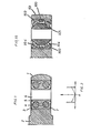
- Fig. 1 is a vertical cross-section illustrating schematically a main embodiment and the resilient pivoting bearing provided according to the invention
- Fig. 2 is an action diagram for the pivoting bearing
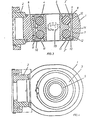
- Fig. 3 is a vertical cross-section on a larger scale and in more detail of the same embodiment
- Fig. 4 is a view of the pivoting bearing according to Fig. 3 as seen from above
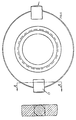
- Figs. 5 and 6 are vertical cross- sections, as seen from above, of the inner sleeve of the bearing
- Fig. 7 is a view, partly in section, of one of the resilient annular members
- Figs. 1 is a vertical cross-section illustrating schematically a main embodiment and the resilient pivoting bearing provided according to the invention
- Fig. 2 is an action diagram for the pivoting bearing
- Fig. 3 is a vertical cross-section on a larger scale and in more detail of the same embodiment
- Fig. 4 is a view of the pivoting bearing according to Fig. 3 as seen from above
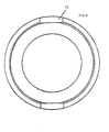
- FIG. 8 and 9 are views of one of the two essentially identical outer sleeves, seen from the centre plane of the bearing and in vertical section, respectively,
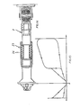
- Fig. 10 is a view, partly in vertical section, of a drawbar equipped with the pivoting bearing and a hydropneumatic double-acting damper;
- Fig. 11 is an action diagram for the same drawbar;
- Fig. 12 is a view of a drawbar equipped with a hydropneumatic damper and a buffer spring;
- Fig. 13 is an action diagram for this drawbar;
- Fig. 14 is a view of a drawbar equipped with double buffer springs and a hydraulic damper;
- Fig. 15 is an action diagram therefor;
- Fig. 10 is a view, partly in vertical section, of a drawbar equipped with the pivoting bearing and a hydropneumatic double-acting damper;
- Fig. 11 is an action diagram for the same drawbar;
- Fig. 12 is a view of a drawbar equipped with a hydro
- FIG. 16 is a view of a drawbar equipped with a resilient pivoting bearing and a double-acting buffer spring;
- Fig. 17 is an action diagram for this drawbar; and
- Fig. 18 is a schematic view, in vertical section a , of an alternative embodiment of the resilient pivoting bearing.
- the resilient pivoting bearing according to the present invention which is adapted to transmit tension and pressure loads between two vehicles, comprises a bearing housing 1 rigidly connected with the drawbar 2 and one of said vehicles, outer sleeves 3 provided in said bearing housing, resilient annular members 4 provided between said outer sleeves 3 and an inner sleeve 5 which has a central opening 6 for receiving a bearing pin (not shown) connected to the other vehicle in some suitable manner.
- the bearing housing 1 rigidly connected to the drawbar 2 has an essentially cylindrical through opening 7 provided at its upper and lower ends with grooves 8 for locking rings 9.
- the outer sleeves 3, of which there is one upper sleeve 3' and one lower sleeve 3" have an essentially cylindrical outer side and are provided in their outer edges with grooves 10 for the said locking rings 9.
- the outer sleeves 3 are provided, at the end which is facing outwardly as seen in the axial direction, with a radially inwardly extending collar or flange 11 from which extends an inwardly circularly curved surface 12 adapted to form a seat for one of the resilient members.
- the curved surface 12 merges with a surface 14 slightly curved towards the inner edge of the respective outer sleeve.
- U-shaped recesses 15 for supporting pins 13 at the inner sleeve 5 are formed at two radially opposed points on the inner edge of the outer sleeve.
- the seats 13 When the outer sleeves are mounted in the bearing housing 1, the seats 13 will be located at an axial distance from one another, and the recesses 15 will together define two opposed radial openings.
- the resilient annular members 4 are in the form of two toroidal rings of suitable rubber material.
- the inner sleeve 5 has an internal cylindrical opening 16 adapted to receive the bearing pin.
- the-inner sleeve On its outer side, the-inner sleeve has a central ridge 17 and at either end a ridge 18 of smaller radial extent. Between the central ridge 17 from which the diametrically opposed pins 13 project, and each of the two end ridges, there is provided a circularly curved circumferential surface 19. Both surfaces form, like the surfaces 12 of the outer sleeves 3, seats for the resilient annular members 4.
- the diameter across the central ridge 17 is larger than the diameter in the end openings at the inwardly facing collars or flanges 11 of the outer sleeves so that the inner sleeve 5 cannot be moved out of the outer sleeves, even if the resilient members should be destroyed. Furthermore, the inner sleeve cannot be rotated relative to the outer sleeve because of the engagement of the pins 13 with the recesses 15.
- the outer sleeves 3 are compressed in the opening 7 of the bearing houses from either side towards the inner sleeve 5 with the resilient annular members 4, such that these members will be inserted in seats, at 12 and 19, on the outer sleeves 3 and the inner sleeve 5 so that the annular members will obtain a predetermined pretension.
- the outer sleeves 3 are fixed by means of the locking rings 9 in the intended position.
- the ridge 17 also serves to form a stop against maximal displacement.
- the pivoting bearing is subjected to a tension or impact load exceeding the load which the resilient rings can absorb, the ridge 17 will engage the opposing portion of the outer sleeve 3, whereby a rigid connection is established between the pin through the pivoting bearing and the drawbar and whereby such excessible loads will be absorbed by a spring and/ or damper means mounted on the drawbar and described below.
- the pivoting bearing is capable of absorbing, on the one hand, radial movements up to a certain limit, during which the spring force increases with the magnitude of the displacement movement, and on the other hand tilting movements during which the annular members are subjected to shear.
- the drawbar 2 connected to the pivoting bearing is provided with a double-acting hydropneumatic damper 20 which, as will appear from Fig. 11, increases the ability to absorb both impacts and jerks.
- the drawbar 2 is provided with a single-acting hydropneumatic damper 21 and a buffer spring 22 for absorbing tension loads.
- the characteristics of the damper and the spring, combined with the characteristic of the pivoting bearing, are shown in Fig. 13.
- the drawbar 2 is provided with hydraulic damper 23 supplemented with a double-acting buffer spring 23, whereby the characteristics shown in Fig. 15 are obtained.
- the drawbar 2 is provided with a double-acting buffer spring 25 only, the effect of which, combined with that of the resilient pivoting bearing, is shown in Fig. 17.
- outer and inner sleeves with seats for annular resilient members
- the resilient members 104 being annular bodies made ofsuitable rubber material andvulcanised to the inner sleeve 105 and the inwardly facing, substantially spherical surfaces of the outer sleeves 103.
- the spacer ring 100 which projects into the free space between the bearing housing 101 and the inner sleeve 105, serves the same purpose as the ridge 17 previously mentioned, i.e. to restrict the displacement between the inner sleeve and the bearing housing so that excessive loads on the annular members are prevented.
- the inner sleeve 105 upon such displacement, thus will engage the ring 100, whereby a rigid connection is established between the pin through the inner sleeve and the drawbar, and the spring and/or damper means will absorb the loads in excess.
- the maximum area of the inner sleeve is such that the inner sleeve cannot be pushed out of the outer sleeves.
Landscapes
- Engineering & Computer Science (AREA)
- Mechanical Engineering (AREA)
- General Engineering & Computer Science (AREA)
- Transportation (AREA)
- Health & Medical Sciences (AREA)
- Child & Adolescent Psychology (AREA)
- Pivots And Pivotal Connections (AREA)
- Support Of The Bearing (AREA)
Abstract
Description
- The present invention relates to an arrangement in a pivoting bearing for coupling drawbars, preferably on railbound vehicles, said pivoting bearing connecting the drawbar which is equipped with coupling means and spring and/or damper means adapted to absorb tension and impact loads, to the vehicle and transmitting pressure and tension loads acting between the vehicle and the drawbar, while simultaneously allowing limited pendulum movement in the vertical direction of the drawbar, in addition to pivotal movement of said drawbar about a pin extending vertically through said pivoting bearing. Such an arrangement is known from DE-B-1 038 592.
- It is the object of this invention to provide a resilient pivoting bearing allowing both pivotal movement about said vertical pin and a certain limited pendulum movement about a horizontal axis located transversely of the directions of the tension and impact loads.
- Another object is to provide a resilient pivoting bearing which is so designed that it retains its connecting function even if, contrary to expectation, the resilient means should be rendered inoperative or be destroyed.
- A further object is to provide a resilient pivoting bearing which can be readily combined with a number of different existing units absorbing impact and tension loads.
- The arrangement according to the invention is substantially characterised in that there are provided, as seen in the direction of said vertical pin, between parts of the pivoting bearing which are rigidly connected to the vehicle and the drawbar in the directions of the pressure and tension loads, annular tension and impact absorbing members of resilient material located at a distance from one another and preferably concentric about the said pin, said annular members being clamped in such a manner between inclined surfaces or seats on an inner bearing part accommodating said pin and an outer bearing part that the drawbar, when unactuated, is held essentially horizontally, and that there is provided at either one of the bearing parts connected to the vehicle and the drawbar, respectively, adjacent said annular members, a portion projecting in the direction of the tension and impact loads and adapted, upon a predetermined maximal compression of said annular members in the direction of the tension or impact load, to engage with an opposing portion for directly transmitting thereto and to the spring and/or damper means of said drawbar tension or impact loads of a magnitude exceeding the load absorbing capacity of said resilient annular members.
- Embodiments of the arrangement according to the invention will be described in more detail below, reference being had to the accompanying drawings in which Fig. 1 is a vertical cross-section illustrating schematically a main embodiment and the resilient pivoting bearing provided according to the invention; Fig. 2 is an action diagram for the pivoting bearing; Fig. 3 is a vertical cross-section on a larger scale and in more detail of the same embodiment; Fig. 4 is a view of the pivoting bearing according to Fig. 3 as seen from above; Figs. 5 and 6 are vertical cross- sections, as seen from above, of the inner sleeve of the bearing; Fig. 7 is a view, partly in section, of one of the resilient annular members; Figs. 8 and 9 are views of one of the two essentially identical outer sleeves, seen from the centre plane of the bearing and in vertical section, respectively, Fig. 10 is a view, partly in vertical section, of a drawbar equipped with the pivoting bearing and a hydropneumatic double-acting damper; Fig. 11 is an action diagram for the same drawbar; Fig. 12 is a view of a drawbar equipped with a hydropneumatic damper and a buffer spring; Fig. 13 is an action diagram for this drawbar; Fig. 14 is a view of a drawbar equipped with double buffer springs and a hydraulic damper; Fig. 15 is an action diagram therefor; Fig. 16 is a view of a drawbar equipped with a resilient pivoting bearing and a double-acting buffer spring; Fig. 17 is an action diagram for this drawbar; and Fig. 18 is a schematic view, in vertical sectiona, of an alternative embodiment of the resilient pivoting bearing.
- The resilient pivoting bearing according to the present invention, which is adapted to transmit tension and pressure loads between two vehicles, comprises a bearing housing 1 rigidly connected with the
drawbar 2 and one of said vehicles,outer sleeves 3 provided in said bearing housing, resilientannular members 4 provided between saidouter sleeves 3 and aninner sleeve 5 which has acentral opening 6 for receiving a bearing pin (not shown) connected to the other vehicle in some suitable manner. - The bearing housing 1 rigidly connected to the
drawbar 2 has an essentially cylindrical through opening 7 provided at its upper and lower ends withgrooves 8 forlocking rings 9. - The
outer sleeves 3, of which there is one upper sleeve 3' and onelower sleeve 3", have an essentially cylindrical outer side and are provided in their outer edges withgrooves 10 for the saidlocking rings 9. - On their inner side, the
outer sleeves 3 are provided, at the end which is facing outwardly as seen in the axial direction, with a radially inwardly extending collar orflange 11 from which extends an inwardly circularlycurved surface 12 adapted to form a seat for one of the resilient members. Thecurved surface 12 merges with asurface 14 slightly curved towards the inner edge of the respective outer sleeve. U-shaped recesses 15 for supportingpins 13 at theinner sleeve 5 are formed at two radially opposed points on the inner edge of the outer sleeve. - When the outer sleeves are mounted in the bearing housing 1, the
seats 13 will be located at an axial distance from one another, and therecesses 15 will together define two opposed radial openings. - In the embodiment illustrated in Figs. 1-17, the resilient
annular members 4 are in the form of two toroidal rings of suitable rubber material. - The
inner sleeve 5 has an internalcylindrical opening 16 adapted to receive the bearing pin. On its outer side, the-inner sleeve has acentral ridge 17 and at either end aridge 18 of smaller radial extent. Between thecentral ridge 17 from which the diametrically opposedpins 13 project, and each of the two end ridges, there is provided a circularly curvedcircumferential surface 19. Both surfaces form, like thesurfaces 12 of theouter sleeves 3, seats for the resilientannular members 4. - The diameter across the
central ridge 17 is larger than the diameter in the end openings at the inwardly facing collars orflanges 11 of the outer sleeves so that theinner sleeve 5 cannot be moved out of the outer sleeves, even if the resilient members should be destroyed. Furthermore, the inner sleeve cannot be rotated relative to the outer sleeve because of the engagement of thepins 13 with therecesses 15. - Upon mounting of the pivoting bearing, the
outer sleeves 3 are compressed in the opening 7 of the bearing houses from either side towards theinner sleeve 5 with the resilientannular members 4, such that these members will be inserted in seats, at 12 and 19, on theouter sleeves 3 and theinner sleeve 5 so that the annular members will obtain a predetermined pretension. Theouter sleeves 3 are fixed by means of thelocking rings 9 in the intended position. - The
ridge 17 also serves to form a stop against maximal displacement. When the pivoting bearing is subjected to a tension or impact load exceeding the load which the resilient rings can absorb, theridge 17 will engage the opposing portion of theouter sleeve 3, whereby a rigid connection is established between the pin through the pivoting bearing and the drawbar and whereby such excessible loads will be absorbed by a spring and/ or damper means mounted on the drawbar and described below. - This arrangement has been made to prevent the resilient rings from being subjected to excessive loads that may damage the resilient material. As is well known, resilient materials can be compressed and extended to a certain limit only, and loads beyond this limit may cause lasting damage. By relieving the resilient rings from loads in excess of a predetermined magnitude, the risk of such damage is eliminated.
- Aswill appearfrom Fig. 2, the pivoting bearing is capable of absorbing, on the one hand, radial movements up to a certain limit, during which the spring force increases with the magnitude of the displacement movement, and on the other hand tilting movements during which the annular members are subjected to shear.
- In the embodiment illustrated in Fig. 10, the
drawbar 2 connected to the pivoting bearing is provided with a double-actinghydropneumatic damper 20 which, as will appear from Fig. 11, increases the ability to absorb both impacts and jerks. - In the embodiment shown in Fig. 12, the
drawbar 2 is provided with a single-actinghydropneumatic damper 21 and abuffer spring 22 for absorbing tension loads. The characteristics of the damper and the spring, combined with the characteristic of the pivoting bearing, are shown in Fig. 13. - In the embodiment shown in Fig. 14, the
drawbar 2 is provided withhydraulic damper 23 supplemented with a double-actingbuffer spring 23, whereby the characteristics shown in Fig. 15 are obtained. - In the embodiment shown in Fig. 16, the
drawbar 2 is provided with a double-actingbuffer spring 25 only, the effect of which, combined with that of the resilient pivoting bearing, is shown in Fig. 17. - As will appear from Fig. 18, the pivoting bearing itself may be designed in an alternative manner.
- Instead of outer and inner sleeves with seats for annular resilient members, use is made of an essentially spherical
inner sleeve 105 andouter sleeves 103 clamped in the opening of the bearinghousing 101 and separated by aspacer ring 100, theresilient members 104 being annular bodies made ofsuitable rubber material andvulcanised to theinner sleeve 105 and the inwardly facing, substantially spherical surfaces of theouter sleeves 103. - The
spacer ring 100 which projects into the free space between the bearinghousing 101 and theinner sleeve 105, serves the same purpose as theridge 17 previously mentioned, i.e. to restrict the displacement between the inner sleeve and the bearing housing so that excessive loads on the annular members are prevented. In the embodiment shown in Fig. 18, theinner sleeve 105, upon such displacement, thus will engage thering 100, whereby a rigid connection is established between the pin through the inner sleeve and the drawbar, and the spring and/or damper means will absorb the loads in excess. - Also in this case, the maximum area of the inner sleeve is such that the inner sleeve cannot be pushed out of the outer sleeves.
- The invention is not restricted to the embodiments described above and shown in the drawings, but may be modified in several ways within the scope of the appended claims.
Claims (3)
Priority Applications (1)
| Application Number | Priority Date | Filing Date | Title |
|---|---|---|---|
| AT85903090T ATE32048T1 (en) | 1984-06-12 | 1985-06-12 | INSTALLATION OF ROTATING BEARINGS FOR DRAWING DEVICES. |
Applications Claiming Priority (2)
| Application Number | Priority Date | Filing Date | Title |
|---|---|---|---|
| SE8403142A SE455692B (en) | 1984-06-12 | 1984-06-12 | DEVICE FOR DRAGON FITTINGS |
| SE8403142 | 1984-06-12 |
Publications (2)
| Publication Number | Publication Date |
|---|---|
| EP0185728A1 EP0185728A1 (en) | 1986-07-02 |
| EP0185728B1 true EP0185728B1 (en) | 1988-01-20 |
Family
ID=20356203
Family Applications (1)
| Application Number | Title | Priority Date | Filing Date |
|---|---|---|---|
| EP19850903090 Expired EP0185728B1 (en) | 1984-06-12 | 1985-06-12 | An arrangement in pivoting bearings for drawgears |
Country Status (6)
| Country | Link |
|---|---|
| EP (1) | EP0185728B1 (en) |
| JP (1) | JPS61502392A (en) |
| AU (1) | AU4497985A (en) |
| DE (1) | DE3561450D1 (en) |
| SE (1) | SE455692B (en) |
| WO (1) | WO1986000053A1 (en) |
Cited By (1)
| Publication number | Priority date | Publication date | Assignee | Title |
|---|---|---|---|---|
| WO2025116804A1 (en) * | 2023-11-30 | 2025-06-05 | Dellner Couplers Ab | Front end for a railway coupler comprising an energy absorber |
Families Citing this family (2)
| Publication number | Priority date | Publication date | Assignee | Title |
|---|---|---|---|---|
| DE8707485U1 (en) * | 1987-05-25 | 1987-07-30 | Dellner Kupplungen GmbH, 4000 Düsseldorf | coupling |
| JP5222965B2 (en) * | 2011-02-15 | 2013-06-26 | 株式会社日本製鋼所 | Shock absorber for railway vehicles |
Family Cites Families (3)
| Publication number | Priority date | Publication date | Assignee | Title |
|---|---|---|---|---|
| DE739988C (en) * | 1938-07-01 | 1943-10-09 | Claere Deiters Geb Gerlinghoff | Automatic trailer coupling |
| US2250425A (en) * | 1939-03-11 | 1941-07-22 | Dornvan Corp | Drawbar and anchor therefor |
| DE1038592B (en) * | 1954-01-29 | 1958-09-11 | Krauss Maffei Ag | Pulling and pushing device for rail vehicles |
-
1984
- 1984-06-12 SE SE8403142A patent/SE455692B/en not_active IP Right Cessation
-
1985
- 1985-06-12 WO PCT/SE1985/000247 patent/WO1986000053A1/en not_active Ceased
- 1985-06-12 EP EP19850903090 patent/EP0185728B1/en not_active Expired
- 1985-06-12 DE DE8585903090T patent/DE3561450D1/en not_active Expired
- 1985-06-12 JP JP60502809A patent/JPS61502392A/en active Pending
- 1985-06-12 AU AU44979/85A patent/AU4497985A/en not_active Abandoned
Cited By (1)
| Publication number | Priority date | Publication date | Assignee | Title |
|---|---|---|---|---|
| WO2025116804A1 (en) * | 2023-11-30 | 2025-06-05 | Dellner Couplers Ab | Front end for a railway coupler comprising an energy absorber |
Also Published As
| Publication number | Publication date |
|---|---|
| AU4497985A (en) | 1986-01-10 |
| DE3561450D1 (en) | 1988-02-25 |
| SE455692B (en) | 1988-08-01 |
| JPS61502392A (en) | 1986-10-23 |
| SE8403142L (en) | 1985-12-13 |
| EP0185728A1 (en) | 1986-07-02 |
| WO1986000053A1 (en) | 1986-01-03 |
| SE8403142D0 (en) | 1984-06-12 |
Similar Documents
| Publication | Publication Date | Title |
|---|---|---|
| US6296237B1 (en) | Bump stopper | |
| US5868415A (en) | Cushion coupler | |
| US6443437B1 (en) | Suspension strut with damping | |
| US4513990A (en) | Bushing structure in a vehicle suspension system | |
| US7172182B2 (en) | Mixed mode mounting assembly for shock/strut rod | |
| US6234460B1 (en) | Push-on air spring bumper | |
| US4738436A (en) | Spring system | |
| US6439794B2 (en) | Compliant pivot socket for automotive steering | |
| US6413003B1 (en) | Compliant pivot socket for automotive steering | |
| JPH11247838A (en) | Ball joint | |
| AU700790B1 (en) | Side strut for the lower steering arm of a tractor | |
| US4974985A (en) | Ball joint | |
| JPS6085003A (en) | Connector for arm and coil compression spring of wheel suspension system for automobile | |
| US3375028A (en) | Ball joint for tie rod or the like | |
| US3650552A (en) | Ball joint, especially for the steering linkage of motor vehicles | |
| US2857056A (en) | Coupling assembly | |
| US5699984A (en) | Energy-absorbing link member and an aircraft seat fitted with such a member | |
| US4210343A (en) | Automotive suspension system | |
| WO1986000053A1 (en) | An arrangement in pivoting bearings for drawgears | |
| US4681235A (en) | Elastic articulation of a central buffer coupling for rail vehicles | |
| JP2002527701A (en) | Elastomer mounting body (C) | |
| US6443439B1 (en) | Elastomeric mounting (B) | |
| US2924469A (en) | Ball joint for independent steerable wheel suspensions | |
| US20050056983A1 (en) | Bushing with controlled elastic absorption of radial stress | |
| EP1179146A1 (en) | Airspring and airspring retainer |
Legal Events
| Date | Code | Title | Description |
|---|---|---|---|
| PUAI | Public reference made under article 153(3) epc to a published international application that has entered the european phase |
Free format text: ORIGINAL CODE: 0009012 |
|
| 17P | Request for examination filed |
Effective date: 19860206 |
|
| AK | Designated contracting states |
Kind code of ref document: A1 Designated state(s): AT BE CH DE FR GB IT LI NL SE |
|
| 17Q | First examination report despatched |
Effective date: 19870413 |
|
| GRAA | (expected) grant |
Free format text: ORIGINAL CODE: 0009210 |
|
| AK | Designated contracting states |
Kind code of ref document: B1 Designated state(s): AT BE CH DE FR GB IT LI NL SE |
|
| REF | Corresponds to: |
Ref document number: 32048 Country of ref document: AT Date of ref document: 19880215 Kind code of ref document: T |
|
| ITF | It: translation for a ep patent filed | ||
| REF | Corresponds to: |
Ref document number: 3561450 Country of ref document: DE Date of ref document: 19880225 |
|
| ET | Fr: translation filed | ||
| PLBE | No opposition filed within time limit |
Free format text: ORIGINAL CODE: 0009261 |
|
| STAA | Information on the status of an ep patent application or granted ep patent |
Free format text: STATUS: NO OPPOSITION FILED WITHIN TIME LIMIT |
|
| 26N | No opposition filed | ||
| ITTA | It: last paid annual fee | ||
| EAL | Se: european patent in force in sweden |
Ref document number: 85903090.0 |
|
| PGFP | Annual fee paid to national office [announced via postgrant information from national office to epo] |
Ref country code: GB Payment date: 19950601 Year of fee payment: 11 |
|
| PGFP | Annual fee paid to national office [announced via postgrant information from national office to epo] |
Ref country code: DE Payment date: 19950607 Year of fee payment: 11 |
|
| PGFP | Annual fee paid to national office [announced via postgrant information from national office to epo] |
Ref country code: FR Payment date: 19950609 Year of fee payment: 11 |
|
| PGFP | Annual fee paid to national office [announced via postgrant information from national office to epo] |
Ref country code: SE Payment date: 19950616 Year of fee payment: 11 |
|
| PGFP | Annual fee paid to national office [announced via postgrant information from national office to epo] |
Ref country code: AT Payment date: 19950621 Year of fee payment: 11 |
|
| PGFP | Annual fee paid to national office [announced via postgrant information from national office to epo] |
Ref country code: CH Payment date: 19950622 Year of fee payment: 11 |
|
| PGFP | Annual fee paid to national office [announced via postgrant information from national office to epo] |
Ref country code: NL Payment date: 19950629 Year of fee payment: 11 |
|
| PGFP | Annual fee paid to national office [announced via postgrant information from national office to epo] |
Ref country code: BE Payment date: 19950630 Year of fee payment: 11 |
|
| PG25 | Lapsed in a contracting state [announced via postgrant information from national office to epo] |
Ref country code: GB Effective date: 19960612 Ref country code: AT Effective date: 19960612 |
|
| PG25 | Lapsed in a contracting state [announced via postgrant information from national office to epo] |
Ref country code: SE Effective date: 19960613 |
|
| PG25 | Lapsed in a contracting state [announced via postgrant information from national office to epo] |
Ref country code: LI Effective date: 19960630 Ref country code: CH Effective date: 19960630 Ref country code: BE Effective date: 19960630 |
|
| BERE | Be: lapsed |
Owner name: DELLNER COUPLERS B.V. Effective date: 19960630 |
|
| PG25 | Lapsed in a contracting state [announced via postgrant information from national office to epo] |
Ref country code: NL Effective date: 19970101 |
|
| GBPC | Gb: european patent ceased through non-payment of renewal fee |
Effective date: 19960612 |
|
| REG | Reference to a national code |
Ref country code: CH Ref legal event code: PL |
|
| PG25 | Lapsed in a contracting state [announced via postgrant information from national office to epo] |
Ref country code: FR Effective date: 19970228 |
|
| PG25 | Lapsed in a contracting state [announced via postgrant information from national office to epo] |
Ref country code: DE Effective date: 19970301 |
|
| EUG | Se: european patent has lapsed |
Ref document number: 85903090.0 |
|
| NLV4 | Nl: lapsed or anulled due to non-payment of the annual fee |
Effective date: 19970101 |
|
| REG | Reference to a national code |
Ref country code: FR Ref legal event code: ST |