EP0185375A2 - Wound rotor arm element and centrifuge rotor fabricated therefrom - Google Patents
Wound rotor arm element and centrifuge rotor fabricated therefrom Download PDFInfo
- Publication number
- EP0185375A2 EP0185375A2 EP85116226A EP85116226A EP0185375A2 EP 0185375 A2 EP0185375 A2 EP 0185375A2 EP 85116226 A EP85116226 A EP 85116226A EP 85116226 A EP85116226 A EP 85116226A EP 0185375 A2 EP0185375 A2 EP 0185375A2
- Authority
- EP
- European Patent Office
- Prior art keywords
- arm
- rotor
- fiber
- arms
- axis
- Prior art date
- Legal status (The legal status is an assumption and is not a legal conclusion. Google has not performed a legal analysis and makes no representation as to the accuracy of the status listed.)
- Granted
Links
Images


Classifications
-
- B—PERFORMING OPERATIONS; TRANSPORTING
- B04—CENTRIFUGAL APPARATUS OR MACHINES FOR CARRYING-OUT PHYSICAL OR CHEMICAL PROCESSES
- B04B—CENTRIFUGES
- B04B5/00—Other centrifuges
- B04B5/04—Radial chamber apparatus for separating predominantly liquid mixtures, e.g. butyrometers
- B04B5/0407—Radial chamber apparatus for separating predominantly liquid mixtures, e.g. butyrometers for liquids contained in receptacles
- B04B5/0414—Radial chamber apparatus for separating predominantly liquid mixtures, e.g. butyrometers for liquids contained in receptacles comprising test tubes
-
- B—PERFORMING OPERATIONS; TRANSPORTING
- B04—CENTRIFUGAL APPARATUS OR MACHINES FOR CARRYING-OUT PHYSICAL OR CHEMICAL PROCESSES
- B04B—CENTRIFUGES
- B04B7/00—Elements of centrifuges
- B04B7/08—Rotary bowls
- B04B7/085—Rotary bowls fibre- or metal-reinforced
Definitions
- This invention relates to a centrifuge rotor and, in particular, to a centrifuge rotor fabricated from an array of stacked wound radial rotor arm elements.
- Typical use of such composite structures is found in the area of energy storage devices, such as fly-wheels.
- Exemplary of various alternate embodiments of such reinforced fiber composite rotatable structures are those shown in United States Patent 4.458,400 (Friedericy et al., composite material flywheel hub formed of stacked fiber-reinforced bars), United States Patent 3,672,241 (Rabenhorst, rotary element formed of layered strips of anisotropic filaments bound in a matrix), United States Patent 3,698.262 (Rabenhorst,rotary element having a central hub with a multiplicity of anisotropic filaments), United States Patent 3,737,694 (Rabenhorst, stacked discs of hub lamina each carrying an array of bent anisotropic fibers), United States Patent 3,884,093 (Rabenhorst, fly-wheel fabricated of sector shaped members centrally connected to a hub. the thickness of each element being greater in the center than at the ends), and United
- reinforced fiber material has also been found in other rotating structures, such as rotor blades and tooling. Exemplary of such uses are those shown in United States Patent 4,038,885 (Jonda) and United States Patent 4,255,087 (Wackerle, et al.). United States Patent 3,262.231 (Polch) discloses the utilization of strands of high-tensile strength material, such as glass, as internal reinforcement of rotatable articles such as abrasive wheels.
- United States Patent 2,447,330 discloses an ultracentrifuge rotor formed of a metal material which is provided with slots which reduce the weight of the rotor.
- United States Patent 3,248,046 discloses a fixed angle centrifuge rotor formed by winding layers of glass material onto a mandrel.
- United States Patent 4,468,269 discloses a rotor with a plurality of rings surrounding a bowl-like body portion.
- This invention relates to a reinforced fiber composite rotor structure capable of rotating a sample carried in a sample carrier at very high speeds.
- the structure in its broadest aspect comprises a generally elongated arm element having an elongated major axis.
- the arm element is formed from a plurality of turns of a fiber material arranged in generally parallel side portions connected through curved end turn portions. With such a structure the fibers forming each element pass as close as possible to the axis of rotation of the rotor and still provide continuous support for the sample carriers along the direction of maximum stress.
- the axes of each of the fibers in each of the side portions are substantially parallel to each other, parallel to the major axis of the elongated arm and substantially perpendicular to the rotor's axis of rotation.
- the height dimension of a side portion of the arm element is preferably less (i.e., the arm is thinner) at a point substantially mid-way along its length than at its curved end turn.
- the cross sectional area taken through a side portion of the arm element is substantially equal to the cross sectional area of the element taken through an end turn portion.
- a sample carrier is connectable to each arm element within each end turn thereof.
- the sample carrier may be tubular segment having a predetermined length which may be provided with a closed end in some instances.
- a drive connection is made to the arm mid-way between the ends of the arm. Transverse and/or inclined reinforcing wrappings and/or bracing fibers may also be provided.
- the rotor takes the form of one, two or more vertical tiers, each tier being formed of a stacked plurality of arm elements.
- N arms are arranged to form an individual tier. where N equals one-half M.
- the major axis of each arm in a tier is offset from the major axis of the adjacent arm in the tier by an angle equal to 180° divided by N.
- the height dimension H of each rotor arm in the vicinity of its center is preferably about 1/N times the height dimension H E at its end, thus permitting the N arms defining a tier to exhibit a substantially uniform height profile to facilitate stacking.
- the height dimension H of each arm may be greater or less than the preferred height dimension ratio discussed above.
- a sample receiving volume adapted to receive a specimen therein.
- the volume may be defined by a continuous carrier that is secured through the vertically registered ends of the elements in each tier.
- a drive fitting having M faces on its periphery passes centrally and axially through the stacked tiers. Each arm element in each tier is connected along a different pair of opposed faces of the fitting.
- a rotor in accordance with this invention may be implemented either in a fixed angle or a vertical tube configuration.
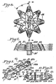
- FIG. 1 shown is an isolated perspective view of an individual wound rotor arm element or arm 10 in accordance with the present invention.
- the arm 10 is a generally elongated element having a major axis 11.
- Each end 12A and 12B of the arm 10 is adapted to receive a sample carrier 14A and 14B respectively.
- the details of the sample carriers 14 and the manner in which they define a sample receiving volume are discussed herein.
- a drive connection 16 is mounted to the arm 10 at a point midway between the ends 12A and 12B thereof. Although it should be appreciated that the drive connection 16 may be provided at any convenient location on the arm 10 providing that symmetry about the centerline CL is maintained.
- the drive connection 16 is shown as a member having opposed flat surfaces 16F which engage the arm 10.
- the drive connection 16 may take any suitable form, as discussed herein, and is arranged to permit the arm 10 to be mounted on a suitable drive spindle or the like for rotation about the axis of rotation CL extending substantially perpendicular to the major axis 11 of the arm 10.
- the arm 10 is formed from a plurality of layered turns of an anisotropic fiber material.
- the arm 10 is wound in a manner to be discussed so as to provide generally parallel side portions 18R and 18L which are connected through curved end turn portions 20A and 20B.
- Each sample carrier 14A and 14B is respectively positioned within its associated end turn portion 20A and 20B.
- the side portions 18 are spaced by a gap 22 having a predetermined dimension.
- the gap 2 2 may remain substantially equal to the diametric dimension of the carrier 14, as shown in Figures 1 and 2.
- the fibers of the arm 10 may partially wrap about the carrier 14, as shown in Figure 3, to define a narrower gap 22'.
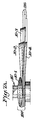
- Each sample carrier 14 is a substantially cylindrical tubular member which may be mounted such that the axis thereof is either parallel to or slightly inclined inwardly with respect to the axis of rotation CL to respectively define a vertical tube rotor (as shown, e.g., in Figures 11 and 12) or a fixed angle rotor as shown in Figures 1. 2, 3 and 4.
- Each carrier 14 may be formed as an open or a closed ended member.
- a closed ended tubular member 1 4 ' is shown in Figures 8 through 10.
- the sample carrier may be provided during fabrication of the arm or thereafter.
- the carrier 14 may directly receive a sample under test or may be sized to receive a separate container (as a test tube) which carries the sample under test.
- a rotor may be formed from at least two stacks of tiers of arms. Each tier is itself formed from a stack of individual arms. In this instance selected arms in each tier lie in vertical registration.
- a sample receiving volume may be defined by the registration of segmented carriers or by the insertion of an integral carrier 14 into the registered ends of the arms.
- the arm 10 is wound such that the side portions 18 are thin rectanguloid members which merge into the flaring, substantially horseshoe-shaped curved end turn portions 20.
- the individual fibers in the side portions 18 are arrayed such that their axes are parallel to each other and to the major axis 11 of the arm 10 while the fibers diverge from each other in the end turn portions 20.
- the fibers are surrounded and supported in a suitable resin-based support matrix 24 best seen in Figures 5A and 5B.
- the arms 10 exhibit a profile in which the height dimension H ( Figure 4) of a side portion 18 (measured in the central region between the flared ends) is less than the height dimension H E of an end portion turn 20.
- H the height dimension of a side portion 18 (measured in the central region between the flared ends) is less than the height dimension H E of an end portion turn 20.
- the profile of the arm element 10 need not be limited to that shown in the Figures.
- the rectanguloid central region of the side portions of the arm may extend for a lesser distance along the length of the side portion and the taper of the end turn portions may concomitantly increase in length and become more gradual.
- the arm 10 shown in Figures 1 through 4 are configured for the fabrication of a fixed angle centrifuge. However, for use in a vertical tube centrifuge arms 10' such as shown in Figures 11 and 12 may be used.
- the arms 10' are identical in all material respects to that discussed in Figures 1 through 4, except that the sample carriers 14 are supported in their associated end turn portions 20 so that the axis 15 of the carrier 14 is parallel to the axis of rotation CL.
- the axes 15 of the carriers 14 are inclined at a predetermined fixed angle to the axis CL.
- the arm 10' may exhibit either gap configuration 22, 22' as shown in Figures 2 or 3.
- transverse centrifugal forces in the region of the drive connection 16 may have a tendency to separate the parallel side portions 18 of the arm in some instances it may be desired to provide wrappings formed of arrays of transversely wound fibers 28A and 28B disposed across the sides 18R and 18L.
- reinforcing fibers 26A and 26B located in the transition region between the sides 18 and the end turns 20 may be provided.
- the windings 26 and/or 28 may be used with any embodiment of the arms 10 or 10' shown herein but are illustrated only in Figures 1 through 3 for clarity of illustration.
- the arm 10 or 10' may be fabricated in any convenient manner as described in connection with Figures 13 through 20.
- the sections 30A and 30B are releasably conjoined by end posts 31.
- the depth of the groove defined about the periphery of the conjoined sections 30A and 30B corresponds to the width of the side portions 18 and end portions 20 of the arm 10 or 10'.
- the mold 30 is mounted for rotational movement about an axle 38 journaled in a fixture 40 mounted on a work table 42.
- Motive energy for rotation of the mold 30 is derived from a motor 44 conveniently mounted to the fixture 40.
- the motor 44 causes the mold 30 to rotate in the direction of the arrows 46.
- a strand of high-tensile strength anisotropic fiber is wrapped in the groove 32 around the mold 30 so as to build-up substantially uniform fiber layers.
- the fiber layers are arranged atop each other from the base of the groove in a manner akin to the winding of a fishing reel with line with the axis of the individual fibers in the side portions of the arms being substantially parallel to each other with the fibers in the end turn diverging as discussed.
- Suitable for use as the fiber is 1140 denier aramid fiber such as that manufactured by E. I. du Pont de Nemours and Company, Inc., and sold under the trademark KEVLARe.
- the fiber wrapped onto the mold is coated with any suitable matrix 24 ( Figures 5A, 58) such as epoxy, thermoplastic or other curable resin which imparts a tackiness to the exterior of the fiber and permits the fiber to adhere to adjacent turns in adjacent layers.
- suitable matrix 24 such as epoxy, thermoplastic or other curable resin which imparts a tackiness to the exterior of the fiber and permits the fiber to adhere to adjacent turns in adjacent layers.
- the fiber is taken from a supply spool 48 mounted on a commercial unwind 50 such as that sold by Compensating Tension Controls, Inc. under model 800C 012.
- the fiber passes over a tensioning arm array 52 and through a vertical guide roll 54 to a horizontal grooved guide roller 56.
- the roller 56 is mounted for traversing movement in the direction of arrows 58 on a shaft 60 of a traverse 62.
- the fiber passes partially around the roller 56.
- the roller 56 may be provided with a nonstick surface to preclude adhesion.
- the guide roller 56 is traversed horizontally (i.e., in a direction parallel to the axis of the shaft 38) as needed to distribute fiber in the groove 32 on the mold 30.
- the base of the groove 32 has been coated with a tacky material, such as a layer of double-stick tape 64.
- a tacky material such as a layer of double-stick tape 64.
- the leading end 66 of the fiber is pressed against the exterior surface of the tape 64 and the mold rotated in the direction 46.
- the fiber adheres to the tape 64 forming the base fiber layer.
- the arm is to be provided with a narrowed gap 22' ( Figure 3)
- the initial turns of fiber are guided onto the tape 6 4 using an implement 68 ( Figure 19) which is urged in an inward direction 70 of the mold 30 to cause the initial layers of the fiber to enter the groove 32 and be forced into place against the tape 64 at the bottom. After a number of initial turns forms a predetermined number of layers the implement 68 is no longer needed.
- a pressing roller 74 is mounted on a fixture 76 for traversing movement in the directions 80 (parallel to the direction 58) ( Figure 13).
- the roller 74 is biased by a spring 82 to press the fiber to preceding layers.
- the traverse of the roller 74 is synchronized with the rotation of the mold to impart a level distribution to the fiber at all points of the mold ( Figure 20).
- the mold sections are preferably bolted in place (by bolts 33 ( Figure 16) extending through posts 31) to apply pressure to the fiber.
- the wound structure After winding the wound structure is generally cured in an autoclave at a temperature and for a time sufficient to release any volatile constituents and/or to cure the matrix so that the resultant wrapped structure becomes a rigid self-supporting member. Thereafter, the mold is disassembled and the composite structure so formed removed.
- the sample carriers 14 (if any) are then secured into the end turn regions 20 of the arm by any suitable means of attachment, such as epoxy glue or the like. Thereafter, the wrappings 26, 28 are wound about the arm.
- the arm 10 or 10' may be wound using ribbons, braids or twisted elements or other textile structural forms. These alternatives lie within the contemplation of the present invention.
- each layer of fiber is arranged in complimentary positions in the end portions 20 and the side portions 18 the arm. Owing to the different shapes of the side portion 18 and the end turn portion, 20 of the arm, individual fibers may shift their relative position with respect to each other as they travel from the central region of the side portions 18 of the rotor arm 10 (or 10') to the end turn portions.
- the general relationship of fibers in the end and side turn regions is indicated in Figures 5A and 5B.
- each of the individual layers 90A through 90D of fibers are arranged to define a predetermined dimension measured in the radial direction 92 from the center line CL that is greater than the corresponding dimension measured in the same direction for the fiber layers in an end turn region ( Figure 5A).
- the fiber layers 90A through 90D exhibit a dimension in the direction 94 parallel to the center axis CL that is greater in the end turn region than the corresponding dimension in the side region as measured in Figure 5B.
- the surface area of a cross section taken through a side portion 18 is equal to the surface area of a cross-section of the arm taken through an end turn 20 ( Figure 5A).
- the fibers in the innermost layer 90A of the end turn portion ( Figure 5A) reorient to form sublayers 90A indicated in the side portion 1 8R ( Figure 5B).
- a similar orientation occurs with layers 90B. 90C and 90D. It should be understood that any predetermined number of layers of fibers may be used, and that the four layers shown in Figures 5A and 5 B are selected only for convenience of illustrating the concepts involved.
- the structures above described can be wound using more than one strand of fiber with the different strands having a relatively higher specific modulus of elasticity being disposed in radially outer layers.
- the inner layer 90A (or innermost layers, as the case may be) may be wound using a fiber having a first specific modulus of elasticity.
- the intermediate layers e.g., the layers 90B and 90C, may thereafter be wound atop the inner layer(s) using a fiber having a relatively greater specific modulus of elasticity (i.e. stiffer).
- the outermost layer 90D may be wound with the fiber having a yet greater specific modulus of elasticity (i.e., stiffer still). Such a constructional arrangement is believed preferable since it more evenly distributes the ability of individual strands and layers of strands to withstand centrifugal stresses.
- the innermost layer may be formed of a K-29 KEVLAR ⁇ aramid fiber, the intermediate layers of the K-49 KEVLARe aramid fiber while the outer layer may be formed of AS4 carbon filament fibers such as that manufactured by Hercules Incorporated, Wilmington, Delaware.
- the arm 10 is wrapped in a manner which closes or narrows the gap 22' between side portions 18.
- This mode of wrapping ensures that the total length of a fiber in a layer on the inner side of a reference line or neutral axis 96 is as close to being equal as possible to the length of a fiber in an outer layer spaced corresponding outwardly with respect to the neutral axis 96.
- Such a winding pattern has a tendency of imparting a more uniform load capability to the fibers.
- Fiber arrangements may include variations in the number of fibers in different locations. For example, additional overwrapped systems (similar to the wrappings 28) in which additional fibers may be added to carry secondary loads.
- a plurality of additional bracing fibers 97 are oriented substantially parallel to the axis of the fibers in the side portions and are placed in high stress regions of the arm to reduce the stress. Generally the fibers 97 are disposed substantially midway along the radial outer surface of each side portion 18 of the arm.
- the additional fibers 97 could be of the form of ribbons, braids or twisted elements.
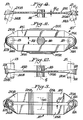
- the individual arm element 10 or 10' may itself act as a sample carrying device, in accordance with a more preferred embodiment of this invention shown in Figures 6 through 8 a plurality of individual arm elements 10 or 10' are stacked atop each other to form a tier 100 having a sample carrying capacity numbered in even number multiples in excess of two.
- a typical one of the tiers 100 is shown in Figure 7A.
- a M place centrifuge rotor where M is an even number greater than two, may be formed from a tier of N arms 10 or 10' angularly arranged with respect to each other about the central axis CL, where N equals one-half M.
- a four-place centrifuge tier (M equals four) may be constructed from two radial arms 10 or 10'.
- the angular spacing between adjacent axes of the arms 10 in the tier is defined by an angle A equal to 180° divided by N, i.e., ninety degrees.
- a six place rotor (M equals six) is defined using three arms (N equals three) with the axis of the arms offset from each other by an angle A of sixty degrees.
- An eight-place rotor may be defined using a tier containing four stacked arms at an angle A of forty-five degrees as shown in Figures 6 through 10.
- the height dimensions H c and HE of each individual arm 10 or 10' are related such that the height dimension HE of an end turn portion 20 of an arm 10 or 10' is substantially equal to N times the height dimension H c .
- the relationship between the heights H c and H E may be related by any predetermined multiple or fraction of the number N. The preferred structural relationship will permit receipt of that number N of arms necessary to form a complete rotor tier 100 to be stacked and received in the overlying central regions where the midpoints of each arm in the tier 100 are in proximity so that the adjacent arms may oriented in the above-described angular relationship.
- a rotor may be formed from a stacked plurality of tiers 100 of arms 10 or 10'.
- This structure may be best understood by reference to Figures 6 through 8 which respectively show a plan, side elevational and a sectional view of an eight place centrifuge rotor fabricated from five stacked tiers 100A through 100E of stacked individual arms 10 or 10'.
- Each tier 100A through 100E contains four arms 10 or 10'.
- such a rotor is arranged such that each arm 10 or 10' in each tier 100 is in vertical registration with respect to the corresponding angularly oriented arm in the next vertically adjacent tier.
- the sample carriers 14 provided at the ends of the same angularly oriented arm in each tier 100 are registered to define an elongated, enclosed sample receiving cavity.
- the carriers 14 disposed in the tiers 100A through 100D are open ended tubular members while the tubular member 14' in the tier 100E is a closed ended tubular member.
- an integral elongated sample carrier may be introduced into the registered ends of the arms and secured in place.
- the sample container may be oriented vertically, i.e., its axis parallel to the centerline CL, or inclined at a fixed angle toward the centerline CL.
- the arms forming each tier are elongated as one proceeds from the upper tier 100A toward the lower tier 100E. Accordingly, the molds used to fabricate the arms for each individual tier must be modified accordingly.
- the arms may be the same length but the segments of the carrier or the elongated carrier may be vertical along the surface reserved in the end turns and provided with an angled inner cavity.
- a rotor may be formed from any predetermined number of tiers.
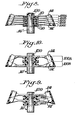
- Each of these Figures disclose a rotor having two tiers 100A and 100B.
- the arms 10 or 10' forming each tier 100A and 100B may be stacked in any predetermined manner as long as their ends cooperably support the sample container.
- Figure 9 discloses a symmetrical stack in which the corresponding arm 10 or 10' in each tier 100A or 100B occupy the same relative position. In the stack shown in Figure 10, the corresponding arms 10 or 10' in each tier 100A and 100B occupy different relative positions in the stack forming each tier.
- the resultant stacked combination of arms is secured together on the drive connection 16' in any convenient manner.
- a threaded fastener 120 ( Figure 7) may be used.
- the arms may be connected to each other by adhesive bonding, by a melted thermoplastic matrix, or by friction provided by pressure from the fastener.
- an individual wound radial arm element and a centrifuge rotor fabricated from a tier of stacked arms or from a plurality of tiers of stacked arms in which the anisotropic fibers in each arm are oriented in a direction arranged to absorb to their maximum the load carried by that arm.
- the rotors described herein are primarily used in ultracentrifuge instruments wherein the rotational speed is in excess of 50,000 revolutions per minute, although it should be understood that their use is not limited exclusively thereto.
Abstract
Description
- This invention relates to a centrifuge rotor and, in particular, to a centrifuge rotor fabricated from an array of stacked wound radial rotor arm elements.
- The trend in the fabrication of rotatable structures has been away from the use of conventional homogeneous materials, such as aluminum or titanium, and toward the use of reinforced fiber composite structures. Such structures are advantageous because they provide an increased strength-to-weight ratio with its attendant advantages over the conventionally fabricated homogeneous structures.
- Typical use of such composite structures is found in the area of energy storage devices, such as fly-wheels. Exemplary of various alternate embodiments of such reinforced fiber composite rotatable structures are those shown in United States Patent 4.458,400 (Friedericy et al., composite material flywheel hub formed of stacked fiber-reinforced bars), United States Patent 3,672,241 (Rabenhorst, rotary element formed of layered strips of anisotropic filaments bound in a matrix), United States Patent 3,698.262 (Rabenhorst,rotary element having a central hub with a multiplicity of anisotropic filaments), United States Patent 3,737,694 (Rabenhorst, stacked discs of hub lamina each carrying an array of bent anisotropic fibers), United States Patent 3,884,093 (Rabenhorst, fly-wheel fabricated of sector shaped members centrally connected to a hub. the thickness of each element being greater in the center than at the ends), and United States Patent 4,028,962 (Nelson. fly-wheel fabricated of anisotropic material in a disc shape with the central portion of the disc being thinner than the edges).
- The use of reinforced fiber material has also been found in other rotating structures, such as rotor blades and tooling. Exemplary of such uses are those shown in United States Patent 4,038,885 (Jonda) and United States Patent 4,255,087 (Wackerle, et al.). United States Patent 3,262.231 (Polch) discloses the utilization of strands of high-tensile strength material, such as glass, as internal reinforcement of rotatable articles such as abrasive wheels.
- In the area of centrifuge rotors the art discloses attempts to increase the strength-to-weight ratio. For example. United States Patent 2,447,330 (Grebmeier) discloses an ultracentrifuge rotor formed of a metal material which is provided with slots which reduce the weight of the rotor. United States Patent 3,248,046 (Feltman et al.) discloses a fixed angle centrifuge rotor formed by winding layers of glass material onto a mandrel. United States Patent 4,468,269 (Carey) discloses a rotor with a plurality of rings surrounding a bowl-like body portion.
- When using reinforced fiber materials it is advantageous to be able to arrange the fibers so that the maximum strength is oriented in a direction parallel to the direction in which maximum centrifugal stress is imposed on the fibers. That is, it is advantageous to be able to provide a three-dimensional spatial relationship of fibers that extend radially outwardly from the central axis of rotation. Most beneficially advantageous is to orient the fibers such that each fiber passes as close as possible through the rotational axis of the structure.
- This invention relates to a reinforced fiber composite rotor structure capable of rotating a sample carried in a sample carrier at very high speeds. The structure in its broadest aspect comprises a generally elongated arm element having an elongated major axis. The arm element is formed from a plurality of turns of a fiber material arranged in generally parallel side portions connected through curved end turn portions. With such a structure the fibers forming each element pass as close as possible to the axis of rotation of the rotor and still provide continuous support for the sample carriers along the direction of maximum stress. The axes of each of the fibers in each of the side portions are substantially parallel to each other, parallel to the major axis of the elongated arm and substantially perpendicular to the rotor's axis of rotation. The height dimension of a side portion of the arm element is preferably less (i.e., the arm is thinner) at a point substantially mid-way along its length than at its curved end turn. The cross sectional area taken through a side portion of the arm element is substantially equal to the cross sectional area of the element taken through an end turn portion. A sample carrier is connectable to each arm element within each end turn thereof. The sample carrier may be tubular segment having a predetermined length which may be provided with a closed end in some instances. A drive connection is made to the arm mid-way between the ends of the arm. Transverse and/or inclined reinforcing wrappings and/or bracing fibers may also be provided.
- In another aspect the rotor takes the form of one, two or more vertical tiers, each tier being formed of a stacked plurality of arm elements. In an M-place rotor. N arms are arranged to form an individual tier. where N equals one-half M. The major axis of each arm in a tier is offset from the major axis of the adjacent arm in the tier by an angle equal to 180° divided by N. In forming a stacked tier the height dimension H of each rotor arm in the vicinity of its center is preferably about 1/N times the height dimension HE at its end, thus permitting the N arms defining a tier to exhibit a substantially uniform height profile to facilitate stacking. Of course the height dimension H of each arm may be greater or less than the preferred height dimension ratio discussed above.
- In rotors formed of at least two tiers, when the tiers are stacked selected ones of the elongated elements in each tier are vertically registered with respect to each other so that the sample carriers segments connectable at each end thereof may communicate to provide a sample receiving volume adapted to receive a specimen therein. Alternatively the volume may be defined by a continuous carrier that is secured through the vertically registered ends of the elements in each tier. A drive fitting having M faces on its periphery passes centrally and axially through the stacked tiers. Each arm element in each tier is connected along a different pair of opposed faces of the fitting.
- A rotor in accordance with this invention may be implemented either in a fixed angle or a vertical tube configuration.
- The invention will be more fully understood from the following detailed description thereof, taken in connection with the accompanying drawings, which form a part of this application and in which:
- Figure 1 is an isolated perspective view of an individual elongated wound radial rotor arm element in accordance with the present invention:
- Figure 2 is a plan view of the wound rotor arm element shown in Figure 1 while Figure 3 is a plan view of an alternate construction of such an arm element;
- Figure 4 is a side elevational view of the rotor arm element shown in Figures 2 and 3;
- Figures 5A and 5B are, respectively, sectional views taken along section lines 5A-5A and 5B-5B in Figure 2:
- Figure 6 is a plan view of an eight-place centrifuge rotor fabricated of a plurality of tiers of rotor arm elements stacked in accordance with the present invention;
- Figure 7 is a side elevational view of the rotor shown in Figure 6 while Figure 7A is an enlarged view of the rotor more clearly illustrating the stepped relationship of the ends of the arms;
- Figure 8 is a section view taken along section lines 8-8 of Figure 6;
- Figures 9 and 10 are alternate configurations of a rotor formed of stacked tiers of wound arm elements in accordance with the present invention;
- Figures 11 and 12 are, respectively. plan and side elevational views (respectively similar to Figures 2 or 3 and Figure 4) illustrating a wound radial arm element in accordance with this invention adapted for the fabrication of a vertical tube centrifuge rotor;
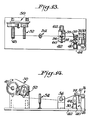
- Figures 13 and 14 are, respectively, a plan and side elevation view of an arrangement for winding a rotor arm in accordance with the present invention;
- Figures 15, 16 and 17 are, respectively, a plan, side elevation and end view of a mold used in winding a rotor arm in accordance with the present invention; and
- Figures 18, 19 and 20 illustrate various procedures used in winding a rotor arm in accordance with the present invention. zr
- Throughout the following detailed description similar reference numerals refer to similar elements in all figures of the drawings.
- With reference to Figure 1 shown is an isolated perspective view of an individual wound rotor arm element or
arm 10 in accordance with the present invention. Thearm 10 is a generally elongated element having a major axis 11. Eachend arm 10 is adapted to receive asample carrier sample carriers 14 and the manner in which they define a sample receiving volume are discussed herein. Adrive connection 16 is mounted to thearm 10 at a point midway between theends drive connection 16 may be provided at any convenient location on thearm 10 providing that symmetry about the centerline CL is maintained. In Figure 1 thedrive connection 16 is shown as a member having opposedflat surfaces 16F which engage thearm 10. Thedrive connection 16 may take any suitable form, as discussed herein, and is arranged to permit thearm 10 to be mounted on a suitable drive spindle or the like for rotation about the axis of rotation CL extending substantially perpendicular to the major axis 11 of thearm 10. - The
arm 10 is formed from a plurality of layered turns of an anisotropic fiber material. Thearm 10 is wound in a manner to be discussed so as to provide generallyparallel side portions end turn portions sample carrier end turn portion gap 22 having a predetermined dimension. The gap 22 may remain substantially equal to the diametric dimension of thecarrier 14, as shown in Figures 1 and 2. Preferably, however. the fibers of thearm 10 may partially wrap about thecarrier 14, as shown in Figure 3, to define a narrower gap 22'. - Each
sample carrier 14 is a substantially cylindrical tubular member which may be mounted such that the axis thereof is either parallel to or slightly inclined inwardly with respect to the axis of rotation CL to respectively define a vertical tube rotor (as shown, e.g., in Figures 11 and 12) or a fixed angle rotor as shown in Figures 1. 2, 3 and 4. Eachcarrier 14 may be formed as an open or a closed ended member. A closed ended tubular member 14' is shown in Figures 8 through 10. The sample carrier may be provided during fabrication of the arm or thereafter. Thecarrier 14 may directly receive a sample under test or may be sized to receive a separate container (as a test tube) which carries the sample under test. As is developed herein (Figures 8, 9 and 10) a rotor may be formed from at least two stacks of tiers of arms. Each tier is itself formed from a stack of individual arms. In this instance selected arms in each tier lie in vertical registration. A sample receiving volume may be defined by the registration of segmented carriers or by the insertion of anintegral carrier 14 into the registered ends of the arms. - As seen with reference to Figures 1 and 3, the
arm 10 is wound such that the side portions 18 are thin rectanguloid members which merge into the flaring, substantially horseshoe-shaped curvedend turn portions 20. As suggested in Figure 4 by the dashed lines, the individual fibers in the side portions 18 are arrayed such that their axes are parallel to each other and to the major axis 11 of thearm 10 while the fibers diverge from each other in theend turn portions 20. - The fibers are surrounded and supported in a suitable resin-based
support matrix 24 best seen in Figures 5A and 5B. Thearms 10 exhibit a profile in which the height dimension H (Figure 4) of a side portion 18 (measured in the central region between the flared ends) is less than the height dimension HE of anend portion turn 20. It should be understood, however, that the profile of thearm element 10 need not be limited to that shown in the Figures. For example, the rectanguloid central region of the side portions of the arm may extend for a lesser distance along the length of the side portion and the taper of the end turn portions may concomitantly increase in length and become more gradual. - The
arm 10 shown in Figures 1 through 4 are configured for the fabrication of a fixed angle centrifuge. However, for use in a vertical tube centrifuge arms 10' such as shown in Figures 11 and 12 may be used. The arms 10' are identical in all material respects to that discussed in Figures 1 through 4, except that thesample carriers 14 are supported in their associatedend turn portions 20 so that theaxis 15 of thecarrier 14 is parallel to the axis of rotation CL. In the fixed angle case shown in Figures 1 through 4, theaxes 15 of thecarriers 14 are inclined at a predetermined fixed angle to the axis CL. It should be noted that the arm 10' may exhibit eithergap configuration 22, 22' as shown in Figures 2 or 3. - Since the transverse centrifugal forces in the region of the
drive connection 16 may have a tendency to separate the parallel side portions 18 of the arm in some instances it may be desired to provide wrappings formed of arrays oftransversely wound fibers sides alternative reinforcing fibers arms 10 or 10' shown herein but are illustrated only in Figures 1 through 3 for clarity of illustration. - The
arm 10 or 10' may be fabricated in any convenient manner as described in connection with Figures 13 through 20. For example, amold 30, preferably formed inconjoinable sections peripheral groove 32 formed in the three-dimensional shape of anindividual arm 10 or 10'. Thesections conjoined sections end portions 20 of thearm 10 or 10'. As seen from Figures 13 and 14 themold 30 is mounted for rotational movement about an axle 38 journaled in afixture 40 mounted on a work table 42. Motive energy for rotation of themold 30 is derived from amotor 44 conveniently mounted to thefixture 40. Themotor 44 causes themold 30 to rotate in the direction of thearrows 46. - A strand of high-tensile strength anisotropic fiber is wrapped in the
groove 32 around themold 30 so as to build-up substantially uniform fiber layers. The fiber layers are arranged atop each other from the base of the groove in a manner akin to the winding of a fishing reel with line with the axis of the individual fibers in the side portions of the arms being substantially parallel to each other with the fibers in the end turn diverging as discussed. Suitable for use as the fiber is 1140 denier aramid fiber such as that manufactured by E. I. du Pont de Nemours and Company, Inc., and sold under the trademark KEVLARe. - The fiber wrapped onto the mold is coated with any suitable matrix 24 (Figures 5A, 58) such as epoxy, thermoplastic or other curable resin which imparts a tackiness to the exterior of the fiber and permits the fiber to adhere to adjacent turns in adjacent layers.
- The fiber is taken from a
supply spool 48 mounted on a commercial unwind 50 such as that sold by Compensating Tension Controls, Inc. under model 800C 012. The fiber passes over atensioning arm array 52 and through avertical guide roll 54 to a horizontalgrooved guide roller 56. Theroller 56 is mounted for traversing movement in the direction ofarrows 58 on ashaft 60 of atraverse 62. The fiber passes partially around theroller 56. Theroller 56 may be provided with a nonstick surface to preclude adhesion. Theguide roller 56 is traversed horizontally (i.e., in a direction parallel to the axis of the shaft 38) as needed to distribute fiber in thegroove 32 on themold 30. - As seen from Figures 18 and 19, the base of the
groove 32 has been coated with a tacky material, such as a layer of double-stick tape 64. The leadingend 66 of the fiber is pressed against the exterior surface of thetape 64 and the mold rotated in thedirection 46. The fiber adheres to the tape 64 forming the base fiber layer. If the arm is to be provided with a narrowed gap 22' (Figure 3) the initial turns of fiber are guided onto the tape 64 using an implement 68 (Figure 19) which is urged in aninward direction 70 of themold 30 to cause the initial layers of the fiber to enter thegroove 32 and be forced into place against thetape 64 at the bottom. After a number of initial turns forms a predetermined number of layers the implement 68 is no longer needed. - A pressing roller 74 is mounted on a
fixture 76 for traversing movement in the directions 80 (parallel to the direction 58) (Figure 13). The roller 74 is biased by a spring 82 to press the fiber to preceding layers. The traverse of the roller 74 is synchronized with the rotation of the mold to impart a level distribution to the fiber at all points of the mold (Figure 20). The mold sections are preferably bolted in place (by bolts 33 (Figure 16) extending through posts 31) to apply pressure to the fiber. - After winding the wound structure is generally cured in an autoclave at a temperature and for a time sufficient to release any volatile constituents and/or to cure the matrix so that the resultant wrapped structure becomes a rigid self-supporting member. Thereafter, the mold is disassembled and the composite structure so formed removed. The sample carriers 14 (if any) are then secured into the
end turn regions 20 of the arm by any suitable means of attachment, such as epoxy glue or the like. Thereafter, the wrappings 26, 28 are wound about the arm. It should be noted that thearm 10 or 10' may be wound using ribbons, braids or twisted elements or other textile structural forms. These alternatives lie within the contemplation of the present invention. - As seen from Figures 5A and 5B the individual fibers in each layer of fiber are arranged in complimentary positions in the
end portions 20 and the side portions 18 the arm. Owing to the different shapes of the side portion 18 and the end turn portion, 20 of the arm, individual fibers may shift their relative position with respect to each other as they travel from the central region of the side portions 18 of the rotor arm 10 (or 10') to the end turn portions. The general relationship of fibers in the end and side turn regions is indicated in Figures 5A and 5B. As seen in these Figures, in aside portion 18R (Figure 5B) each of theindividual layers 90A through 90D of fibers are arranged to define a predetermined dimension measured in theradial direction 92 from the center line CL that is greater than the corresponding dimension measured in the same direction for the fiber layers in an end turn region (Figure 5A). Conversely, in theend turn region 20 as shown on these Figures the fiber layers 90A through 90D exhibit a dimension in thedirection 94 parallel to the center axis CL that is greater in the end turn region than the corresponding dimension in the side region as measured in Figure 5B. However, it is noted that the surface area of a cross section taken through a side portion 18 (Figure 5B) is equal to the surface area of a cross-section of the arm taken through an end turn 20 (Figure 5A). Basically there is a reorientation of the fibers during the transition from the end region 20 (Figure 5A) to the side region 18 (Figure 5B). The fibers in theinnermost layer 90A of the end turn portion (Figure 5A) reorient to formsublayers 90A indicated in the side portion 18R (Figure 5B). A similar orientation occurs with layers 90B. 90C and 90D. It should be understood that any predetermined number of layers of fibers may be used, and that the four layers shown in Figures 5A and 5B are selected only for convenience of illustrating the concepts involved. - Several desirable winding modifications can be effected. For example, the structures above described can be wound using more than one strand of fiber with the different strands having a relatively higher specific modulus of elasticity being disposed in radially outer layers. By way of simplified example, with reference to Figures 5A and 5B, the
inner layer 90A (or innermost layers, as the case may be) may be wound using a fiber having a first specific modulus of elasticity. The intermediate layers, e.g., the layers 90B and 90C, may thereafter be wound atop the inner layer(s) using a fiber having a relatively greater specific modulus of elasticity (i.e. stiffer). Theoutermost layer 90D (or outermost layers) may be wound with the fiber having a yet greater specific modulus of elasticity (i.e., stiffer still). Such a constructional arrangement is believed preferable since it more evenly distributes the ability of individual strands and layers of strands to withstand centrifugal stresses. In the above example the innermost layer may be formed of a K-29 KEVLARΦ aramid fiber, the intermediate layers of the K-49 KEVLARe aramid fiber while the outer layer may be formed of AS4 carbon filament fibers such as that manufactured by Hercules Incorporated, Wilmington, Delaware. - In the alternate embodiment of the arm shown in Figure 3 the
arm 10 is wrapped in a manner which closes or narrows the gap 22' between side portions 18. This mode of wrapping ensures that the total length of a fiber in a layer on the inner side of a reference line orneutral axis 96 is as close to being equal as possible to the length of a fiber in an outer layer spaced corresponding outwardly with respect to theneutral axis 96. Such a winding pattern has a tendency of imparting a more uniform load capability to the fibers. - Other possible fiber arrangements may include variations in the number of fibers in different locations. For example, additional overwrapped systems (similar to the wrappings 28) in which additional fibers may be added to carry secondary loads.
- In another example a plurality of additional bracing fibers 97 are oriented substantially parallel to the axis of the fibers in the side portions and are placed in high stress regions of the arm to reduce the stress. Generally the fibers 97 are disposed substantially midway along the radial outer surface of each side portion 18 of the arm. The additional fibers 97 could be of the form of ribbons, braids or twisted elements.
- Although, with symmetric loading, the
individual arm element 10 or 10' may itself act as a sample carrying device, in accordance with a more preferred embodiment of this invention shown in Figures 6 through 8 a plurality ofindividual arm elements 10 or 10' are stacked atop each other to form atier 100 having a sample carrying capacity numbered in even number multiples in excess of two. A typical one of thetiers 100 is shown in Figure 7A. Thus, a M place centrifuge rotor, where M is an even number greater than two, may be formed from a tier ofN arms 10 or 10' angularly arranged with respect to each other about the central axis CL, where N equals one-half M. Thus, for example, a four-place centrifuge tier (M equals four) may be constructed from tworadial arms 10 or 10'. The angular spacing between adjacent axes of thearms 10 in the tier is defined by an angle A equal to 180° divided by N, i.e., ninety degrees. As a further example, a six place rotor (M equals six) is defined using three arms (N equals three) with the axis of the arms offset from each other by an angle A of sixty degrees. An eight-place rotor may be defined using a tier containing four stacked arms at an angle A of forty-five degrees as shown in Figures 6 through 10. - When used to form a rotor from single or multiple stacked tiers of arms the height dimensions Hc and HE of each
individual arm 10 or 10' are related such that the height dimension HE of anend turn portion 20 of anarm 10 or 10' is substantially equal to N times the height dimension Hc. Although this relationship is preferred the relationship between the heights Hc and HE may be related by any predetermined multiple or fraction of the number N. The preferred structural relationship will permit receipt of that number N of arms necessary to form acomplete rotor tier 100 to be stacked and received in the overlying central regions where the midpoints of each arm in thetier 100 are in proximity so that the adjacent arms may oriented in the above-described angular relationship. It should be noted that in practice it may be necessary to provide a spacer formed with a layer of bonding material on the top and bottom surfaces intermediate each arm in the tier. Such a spacer would thus mandate that the height H be slightly less than 1/N of the height HE to accommodate the spacer. - In the central region where the N arms in a tier cross the vertical registration of the arms forms an M-sided space. Into this space a drive connection 16' (Figure 6). having at least M corresponding surfaces may be introduced. The radial inner surface of both side portions of each arm in the tier is connected directly or through an intermediate element to one of a different opposed pair of surfaces on the
drive connection 161. - In a further aspect of the invention, a rotor may be formed from a stacked plurality of
tiers 100 ofarms 10 or 10'. This structure may be best understood by reference to Figures 6 through 8 which respectively show a plan, side elevational and a sectional view of an eight place centrifuge rotor fabricated from five stackedtiers 100A through 100E of stackedindividual arms 10 or 10'. Eachtier 100A through 100E contains fourarms 10 or 10'. As seen in these Figures, such a rotor is arranged such that eacharm 10 or 10' in eachtier 100 is in vertical registration with respect to the corresponding angularly oriented arm in the next vertically adjacent tier. Thesample carriers 14 provided at the ends of the same angularly oriented arm in eachtier 100 are registered to define an elongated, enclosed sample receiving cavity. Thecarriers 14 disposed in thetiers 100A through 100D are open ended tubular members while the tubular member 14' in thetier 100E is a closed ended tubular member. Alternatively an integral elongated sample carrier may be introduced into the registered ends of the arms and secured in place. - Due to the vertical stacking arrangement the ends of the arms forming a
tier 100 are vertically stepped. This stepped effect is believed best shown in Figure 7A where it is seen that the lower surface of the eacharm 10 or 10' in atypical tier 100 is vertically offset by adistance 116. In Figure 7A, to more clearly illustrate this effect, only the arms 10-1. 10-2. 10-3 and 10-4 forming thetier 100 are illustrated. - The sample container may be oriented vertically, i.e., its axis parallel to the centerline CL, or inclined at a fixed angle toward the centerline CL. In the instance of a stacked fixed angle rotor as shown in Figures 6 through 8, the arms forming each tier are elongated as one proceeds from the
upper tier 100A toward thelower tier 100E. Accordingly, the molds used to fabricate the arms for each individual tier must be modified accordingly. Alternatively, the arms may be the same length but the segments of the carrier or the elongated carrier may be vertical along the surface reserved in the end turns and provided with an angled inner cavity. - As seen from Figures 9 and 10, a rotor may be formed from any predetermined number of tiers. Each of these Figures disclose a rotor having two
tiers arms 10 or 10' forming eachtier corresponding arm 10 or 10' in eachtier arms 10 or 10' in eachtier - By whatever stacking arrangement utilized and by whatever number of tiers desired the resultant stacked combination of arms is secured together on the drive connection 16' in any convenient manner. For example. a threaded fastener 120 (Figure 7) may be used. Alternatively, the arms may be connected to each other by adhesive bonding, by a melted thermoplastic matrix, or by friction provided by pressure from the fastener.
- In view of the foregoing there has been disclosed an individual wound radial arm element and a centrifuge rotor fabricated from a tier of stacked arms or from a plurality of tiers of stacked arms in which the anisotropic fibers in each arm are oriented in a direction arranged to absorb to their maximum the load carried by that arm. The rotors described herein are primarily used in ultracentrifuge instruments wherein the rotational speed is in excess of 50,000 revolutions per minute, although it should be understood that their use is not limited exclusively thereto.
Claims (15)
Priority Applications (1)
| Application Number | Priority Date | Filing Date | Title |
|---|---|---|---|
| AT85116226T ATE47333T1 (en) | 1984-12-21 | 1985-12-19 | WOUND ROTOR ARM ELEMENT AND CENTRIFUGE ROTOR MADE THEREOF. |
Applications Claiming Priority (2)
| Application Number | Priority Date | Filing Date | Title |
|---|---|---|---|
| US68493784A | 1984-12-21 | 1984-12-21 | |
| US684937 | 1984-12-21 |
Publications (3)
| Publication Number | Publication Date |
|---|---|
| EP0185375A2 true EP0185375A2 (en) | 1986-06-25 |
| EP0185375A3 EP0185375A3 (en) | 1987-12-09 |
| EP0185375B1 EP0185375B1 (en) | 1989-10-18 |
Family
ID=24750142
Family Applications (1)
| Application Number | Title | Priority Date | Filing Date |
|---|---|---|---|
| EP85116226A Expired EP0185375B1 (en) | 1984-12-21 | 1985-12-19 | Wound rotor arm element and centrifuge rotor fabricated therefrom |
Country Status (7)
| Country | Link |
|---|---|
| EP (1) | EP0185375B1 (en) |
| JP (1) | JPS61153164A (en) |
| AT (1) | ATE47333T1 (en) |
| DE (1) | DE3573738D1 (en) |
| DK (1) | DK597985A (en) |
| GR (1) | GR853119B (en) |
| IE (1) | IE57149B1 (en) |
Cited By (2)
| Publication number | Priority date | Publication date | Assignee | Title |
|---|---|---|---|---|
| EP0256543A2 (en) * | 1986-08-19 | 1988-02-24 | E.I. Du Pont De Nemours And Company | Laminated arm composite centrifuge rotor |
| EP0290686A1 (en) * | 1986-04-09 | 1988-11-17 | Beckman Instruments, Inc. | Composite material rotor |
Families Citing this family (1)
| Publication number | Priority date | Publication date | Assignee | Title |
|---|---|---|---|---|
| US8328708B2 (en) * | 2009-12-07 | 2012-12-11 | Fiberlite Centrifuge, Llc | Fiber-reinforced swing bucket centrifuge rotor and related methods |
Citations (6)
| Publication number | Priority date | Publication date | Assignee | Title |
|---|---|---|---|---|
| US2447330A (en) * | 1946-05-16 | 1948-08-17 | Grebmeier Joseph | Rotor for ultracentrifuge machines |
| US3765267A (en) * | 1969-05-20 | 1973-10-16 | Aerospatiale | Connecting element between two members enabling them to rotate in relation to one another in three axes |
| DE2741603A1 (en) * | 1976-09-16 | 1978-03-23 | Zeller Corp | Constant velocity universal joint for torque transmission - uses high strength fibres bridging gap between discs on shaft ends |
| GB2001290A (en) * | 1977-07-22 | 1979-01-31 | Messerschmitt Boelkow Blohm | Rotor head assembly primarily for a helicopter |
| EP0033765A1 (en) * | 1980-02-08 | 1981-08-19 | Sigri Elektrographit Gmbh | Connecting rod made of composite material |
| GB2097297A (en) * | 1981-04-24 | 1982-11-03 | Hitachi Koki Kk | Rotor for use in centrifugal separators |
-
1985
- 1985-12-19 EP EP85116226A patent/EP0185375B1/en not_active Expired
- 1985-12-19 AT AT85116226T patent/ATE47333T1/en not_active IP Right Cessation
- 1985-12-19 IE IE3240/85A patent/IE57149B1/en unknown
- 1985-12-19 DE DE8585116226T patent/DE3573738D1/en not_active Expired
- 1985-12-20 DK DK597985A patent/DK597985A/en not_active Application Discontinuation
- 1985-12-20 JP JP60285951A patent/JPS61153164A/en active Granted
- 1985-12-20 GR GR853119A patent/GR853119B/el unknown
Patent Citations (6)
| Publication number | Priority date | Publication date | Assignee | Title |
|---|---|---|---|---|
| US2447330A (en) * | 1946-05-16 | 1948-08-17 | Grebmeier Joseph | Rotor for ultracentrifuge machines |
| US3765267A (en) * | 1969-05-20 | 1973-10-16 | Aerospatiale | Connecting element between two members enabling them to rotate in relation to one another in three axes |
| DE2741603A1 (en) * | 1976-09-16 | 1978-03-23 | Zeller Corp | Constant velocity universal joint for torque transmission - uses high strength fibres bridging gap between discs on shaft ends |
| GB2001290A (en) * | 1977-07-22 | 1979-01-31 | Messerschmitt Boelkow Blohm | Rotor head assembly primarily for a helicopter |
| EP0033765A1 (en) * | 1980-02-08 | 1981-08-19 | Sigri Elektrographit Gmbh | Connecting rod made of composite material |
| GB2097297A (en) * | 1981-04-24 | 1982-11-03 | Hitachi Koki Kk | Rotor for use in centrifugal separators |
Cited By (3)
| Publication number | Priority date | Publication date | Assignee | Title |
|---|---|---|---|---|
| EP0290686A1 (en) * | 1986-04-09 | 1988-11-17 | Beckman Instruments, Inc. | Composite material rotor |
| EP0256543A2 (en) * | 1986-08-19 | 1988-02-24 | E.I. Du Pont De Nemours And Company | Laminated arm composite centrifuge rotor |
| EP0256543A3 (en) * | 1986-08-19 | 1989-11-29 | E.I. Du Pont De Nemours And Company | Laminated arm composite centrifuge rotor |
Also Published As
| Publication number | Publication date |
|---|---|
| GR853119B (en) | 1986-04-22 |
| DK597985A (en) | 1986-06-22 |
| DE3573738D1 (en) | 1989-11-23 |
| EP0185375B1 (en) | 1989-10-18 |
| IE853240L (en) | 1986-06-21 |
| JPS647830B2 (en) | 1989-02-10 |
| ATE47333T1 (en) | 1989-11-15 |
| EP0185375A3 (en) | 1987-12-09 |
| IE57149B1 (en) | 1992-05-06 |
| DK597985D0 (en) | 1985-12-20 |
| JPS61153164A (en) | 1986-07-11 |
Similar Documents
| Publication | Publication Date | Title |
|---|---|---|
| US4860610A (en) | Wound rotor element and centrifuge fabricated therefrom | |
| US4991462A (en) | Flexible composite ultracentrifuge rotor | |
| US5601522A (en) | Fixed angle composite centrifuge rotor fabrication with filament windings on angled surfaces | |
| US3917352A (en) | Continuous-strand, fiber reinforced plastic wheel | |
| US5382219A (en) | Ultra-light composite centrifuge rotor | |
| US4264278A (en) | Blade or spar | |
| JP5972170B2 (en) | Fixed angle centrifugal rotor with tubular cavity and associated method | |
| EP0643628B1 (en) | Fixed-angle composite centrifuge rotor | |
| EP0283098A2 (en) | A centrifuge for separating liquids | |
| US4701157A (en) | Laminated arm composite centrifuge rotor | |
| JPS6270176A (en) | Method and device for simultaneously winding plurality of separated wire on rotating supporter | |
| EP0185375B1 (en) | Wound rotor arm element and centrifuge rotor fabricated therefrom | |
| US20080093002A1 (en) | Elastomeric tire | |
| GB2041858A (en) | improvements in and Relating to Torque Transmitting Members | |
| US4187738A (en) | Rim for rotary inertial energy storage device and method | |
| US5763079A (en) | Wire preforms for composite material manufacture and methods of making | |
| US5284420A (en) | Plastics multi-blade variable-pitch rotor | |
| JPH07507015A (en) | Structural and other components, manufacturing methods | |
| EP0210563B1 (en) | Centrifuge rotor | |
| EP0485443B1 (en) | Tension band centrifuge rotor | |
| JPH07164542A (en) | Production device for fiber-reinforced resin component part and method thereof | |
| JPS6329139B2 (en) | ||
| SU1553234A1 (en) | Arrangement for making jagged rods type articles | |
| WO1994019986A1 (en) | Rotary brush |
Legal Events
| Date | Code | Title | Description |
|---|---|---|---|
| PUAI | Public reference made under article 153(3) epc to a published international application that has entered the european phase |
Free format text: ORIGINAL CODE: 0009012 |
|
| AK | Designated contracting states |
Kind code of ref document: A2 Designated state(s): AT BE CH DE FR GB IT LI LU NL SE |
|
| PUAL | Search report despatched |
Free format text: ORIGINAL CODE: 0009013 |
|
| AK | Designated contracting states |
Kind code of ref document: A3 Designated state(s): AT BE CH DE FR GB IT LI LU NL SE |
|
| 17P | Request for examination filed |
Effective date: 19880204 |
|
| 17Q | First examination report despatched |
Effective date: 19880725 |
|
| GRAA | (expected) grant |
Free format text: ORIGINAL CODE: 0009210 |
|
| AK | Designated contracting states |
Kind code of ref document: B1 Designated state(s): AT BE CH DE FR GB IT LI LU NL SE |
|
| REF | Corresponds to: |
Ref document number: 47333 Country of ref document: AT Date of ref document: 19891115 Kind code of ref document: T |
|
| ITF | It: translation for a ep patent filed |
Owner name: ING. C. GREGORJ S.P.A. |
|
| REF | Corresponds to: |
Ref document number: 3573738 Country of ref document: DE Date of ref document: 19891123 |
|
| PG25 | Lapsed in a contracting state [announced via postgrant information from national office to epo] |
Ref country code: LU Free format text: LAPSE BECAUSE OF NON-PAYMENT OF DUE FEES Effective date: 19891231 |
|
| ET | Fr: translation filed | ||
| PLBE | No opposition filed within time limit |
Free format text: ORIGINAL CODE: 0009261 |
|
| STAA | Information on the status of an ep patent application or granted ep patent |
Free format text: STATUS: NO OPPOSITION FILED WITHIN TIME LIMIT |
|
| PGFP | Annual fee paid to national office [announced via postgrant information from national office to epo] |
Ref country code: FR Payment date: 19900822 Year of fee payment: 6 |
|
| PGFP | Annual fee paid to national office [announced via postgrant information from national office to epo] |
Ref country code: DE Payment date: 19900824 Year of fee payment: 6 |
|
| PGFP | Annual fee paid to national office [announced via postgrant information from national office to epo] |
Ref country code: SE Payment date: 19900827 Year of fee payment: 6 |
|
| PGFP | Annual fee paid to national office [announced via postgrant information from national office to epo] |
Ref country code: CH Payment date: 19900828 Year of fee payment: 6 |
|
| PGFP | Annual fee paid to national office [announced via postgrant information from national office to epo] |
Ref country code: LU Payment date: 19900912 Year of fee payment: 6 |
|
| PGFP | Annual fee paid to national office [announced via postgrant information from national office to epo] |
Ref country code: BE Payment date: 19900913 Year of fee payment: 6 |
|
| 26N | No opposition filed | ||
| PGFP | Annual fee paid to national office [announced via postgrant information from national office to epo] |
Ref country code: GB Payment date: 19900928 Year of fee payment: 6 |
|
| PGFP | Annual fee paid to national office [announced via postgrant information from national office to epo] |
Ref country code: AT Payment date: 19901211 Year of fee payment: 6 |
|
| ITTA | It: last paid annual fee | ||
| PGFP | Annual fee paid to national office [announced via postgrant information from national office to epo] |
Ref country code: NL Payment date: 19901231 Year of fee payment: 6 |
|
| PG25 | Lapsed in a contracting state [announced via postgrant information from national office to epo] |
Ref country code: GB Effective date: 19911219 Ref country code: AT Effective date: 19911219 |
|
| PG25 | Lapsed in a contracting state [announced via postgrant information from national office to epo] |
Ref country code: SE Effective date: 19911220 |
|
| PG25 | Lapsed in a contracting state [announced via postgrant information from national office to epo] |
Ref country code: LI Effective date: 19911231 Ref country code: CH Effective date: 19911231 Ref country code: BE Effective date: 19911231 |
|
| BERE | Be: lapsed |
Owner name: E.I. DU PONT DE NEMOURS AND CY Effective date: 19911231 |
|
| PG25 | Lapsed in a contracting state [announced via postgrant information from national office to epo] |
Ref country code: NL Effective date: 19920701 |
|
| NLV4 | Nl: lapsed or anulled due to non-payment of the annual fee | ||
| GBPC | Gb: european patent ceased through non-payment of renewal fee | ||
| PG25 | Lapsed in a contracting state [announced via postgrant information from national office to epo] |
Ref country code: FR Effective date: 19920831 |
|
| REG | Reference to a national code |
Ref country code: CH Ref legal event code: PL |
|
| PG25 | Lapsed in a contracting state [announced via postgrant information from national office to epo] |
Ref country code: DE Effective date: 19920901 |
|
| REG | Reference to a national code |
Ref country code: FR Ref legal event code: ST |
|
| EUG | Se: european patent has lapsed |
Ref document number: 85116226.3 Effective date: 19920704 |