EP0185190A1 - Procédé pour la mesure continue de la production d'un liquide dans un mélange liquide/gaz et appareil de mesure pour l'application de ce procédé - Google Patents
Procédé pour la mesure continue de la production d'un liquide dans un mélange liquide/gaz et appareil de mesure pour l'application de ce procédé Download PDFInfo
- Publication number
- EP0185190A1 EP0185190A1 EP85114267A EP85114267A EP0185190A1 EP 0185190 A1 EP0185190 A1 EP 0185190A1 EP 85114267 A EP85114267 A EP 85114267A EP 85114267 A EP85114267 A EP 85114267A EP 0185190 A1 EP0185190 A1 EP 0185190A1
- Authority
- EP
- European Patent Office
- Prior art keywords
- float
- receiver
- liquid
- meter
- cylindrical
- Prior art date
- Legal status (The legal status is an assumption and is not a legal conclusion. Google has not performed a legal analysis and makes no representation as to the accuracy of the status listed.)
- Withdrawn
Links
Images


Classifications
-
- G—PHYSICS
- G01—MEASURING; TESTING
- G01F—MEASURING VOLUME, VOLUME FLOW, MASS FLOW OR LIQUID LEVEL; METERING BY VOLUME
- G01F1/00—Measuring the volume flow or mass flow of fluid or fluent solid material wherein the fluid passes through a meter in a continuous flow
- G01F1/05—Measuring the volume flow or mass flow of fluid or fluent solid material wherein the fluid passes through a meter in a continuous flow by using mechanical effects
- G01F1/52—Measuring the volume flow or mass flow of fluid or fluent solid material wherein the fluid passes through a meter in a continuous flow by using mechanical effects by measuring the height of the fluid level due to the lifting power of the fluid flow
-
- A—HUMAN NECESSITIES
- A01—AGRICULTURE; FORESTRY; ANIMAL HUSBANDRY; HUNTING; TRAPPING; FISHING
- A01J—MANUFACTURE OF DAIRY PRODUCTS
- A01J5/00—Milking machines or devices
- A01J5/007—Monitoring milking processes; Control or regulation of milking machines
- A01J5/01—Milkmeters; Milk flow sensing devices
-
- G—PHYSICS
- G01—MEASURING; TESTING
- G01F—MEASURING VOLUME, VOLUME FLOW, MASS FLOW OR LIQUID LEVEL; METERING BY VOLUME
- G01F15/00—Details of, or accessories for, apparatus of groups G01F1/00 - G01F13/00 insofar as such details or appliances are not adapted to particular types of such apparatus
- G01F15/08—Air or gas separators in combination with liquid meters; Liquid separators in combination with gas-meters
Definitions
- the present invention relates to a method for measuring the production of liquid from a streaming liquid-gas mixture and, in particular, to the measurement of the quantity of milk received from an individual animal in a dairy.
- the present invention also relates to a meter that enables one to carry out such a method.
- the milk yielded by the animals is collected in a milk pipeline, to which several milking apparatus are coupled.
- This pipeline carries the air/milk mixture to an air separator from which the milk is pumpe.d to its specific storage or processing place.
- Individual meters enable one to verify the individual production of each animal milked and can serve as the means for automatically removing the milking apparatus from the udder when the milking is finished.
- Such meters consist of a receiver with a single or double chamber, whereby the quantity of milk is registered in a volumetric or dynamic way or by weighing.
- the apparatus In order to obtain good quality milk, the apparatus must be provided with means which can be cleaned and disinfected thoroughly. Up to now these meters were complicated, rather expensive and often difficult to clean and to maintain.
- the object of the invention is to provide a more simple method to measure the production of liquid from a liquid-gas mixture by means of an apparatus that works economically and efficiently.
- a method for continuously measuring the production of liquid from a streaming liquid-gas mixture which comprises separating liquid produced from the liquid-gas mixture by projecting the liquid along the surface of a cylindrical receiver, while the gas from the mixture is sucked up into a tube-like float, located internally and concentric to said cylindrical surface, said float moving up and down in accordance with the quantity of liquid which is drawn off at the bottom of the cylindrical receiver through an outlet-funnel on which said float is supported.
- the oscillations of the float are representative of the quantity of liquid that streams through the meter and said fluctuations are transmitted to a counter which displays the liquid production in litres.
- the meter in accordance with the invention which enables one to carry out said method consists of a cylindrical hollow float which moves up and down in a float chamber consisting of :
- the invention provides a meter for continuously measuring the production of liquid from a streaming liquid-gas mixture, comprising a receiver and a hollow float which moves up and down in said receiver, the receiver consisting of a cylindrical jacket, an upper part and a lower part, and said float consisting of a tube provided with holes and a conical funnel, the cylindrical jacket being provided at its top with a supply-tube which is mounted slantwise thereon, the upper part of the receiver being provided at its bottom with a circular slot with an outer diameter smaller than the diameter of the cylindrical jacket and which is placed with its opening towards said cylindrical jacket at the level of said supply-tube, and the lower part of the receiver being provided with means to hold upright the float and with an outlet-funnel with which the conical funnel of the float engages in use, whereby the upper part of the receiver and the top of the float are provided with respective components of an oscillation meter which registers the fluctuations of the float in the receiver.
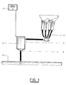
- the milk meter (2) in accordance with the invention is mounted between the milking apparatus (1) and the milk pipeline (3).
- the conduit that comes from the milking apparatus (1) is connected to the milk supply tube (5) of the milk meter (2).
- the milk pipeline (3) which Lakes care of the vacuum-supply as well as of the milk discharge is mounted on the milk-outlet (6) of the milk meter (2). Electric signals coming from the milk meter (2) in accordance with the quantity of milk produced are processed and displayed in the milk meter operating panel (4) with digital display.
- the milk meter (2) in accordance with the invention is constructed of materials which satisfy the norms set by the food industry. It is composed of different, detachable parts.
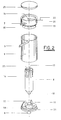
- the main elements of the milk meter (2) are a milk receiver and a float (8) (figs. 2,3 and 5).
- the milk receiver itself is composed of a transparent, cylindrical jacket (9), provided at its upper end with a supply tube (5), mounted slantwise on the jacket (9), to which the conduit coming from the milk apparatus (1) is connected - an upper part (20) and a lower part (21).
- the upper part (20) is fixed airtight to the jacket (9) with a sealing-ring (19) and is provided in the middle with a cylindrical cavity which acts as a stabilization chamber for the tube-like float (8) during its up and down movement, and with a circular slot (15) at its bottom of which the opening passes along the cylindrical surface of the jacket (9) at the level of the supply-tube (5) which is connected with a conduit coming from the milking apparatus.
- the upper part (20) is also provided with a wash-junction (7) which leads tangentially into the stabilization chamber for the tube-like float (8). Through this wash-junction (7) water can be injected in order to clean the milk meter (2).
- the upper part (20) is provided with a centrally mounted component of an oscillation meter (14) which is connected with the milk meter operating panel .(4) by a wire (22).
- This component (14) is protected by a removable lid (23) fixed on the upper part (20).
- the lower part (21) is fixed airtight to the jacket (9) with a sealing-ring (19) but can also form part of the jacket (9).
- the lower part (21) is provided with means to hold upright; the tube-like float (8) represented in figs. 2,3 and 5 in the form of two or more vertical pins (11) which are placed round an imaginary circle with a diameter equal to the inner diameter of the cylindrical stabilization chamber of the upper part (20) and a conical outlet-funnel (10), with the milk-outlet (6) connected with the milk pipeline (3).
- a tube-like float (8) which narrows at its bottom into a conical funnel (18) with two successive angular points, is placed.
- the gradient of the cone of the outlet-funnel (10) is worked out in such a way that the funnel (18) touches the outlet-funnel (10) with . truncated cone surface so that the outlet-funnel (10) also functions as a seat for the tube-like float (8), while the vertical pins (11) function as guides for the said float (8) when it floats up and down.
- the milk meter (2) in accordance with the invention operates as follows.
- the vacuum supplied by the milk installation and the pulsator device causes the flowing of the milk-air mixture towards the supply-tube (5).
- the mixture flows tangentially via the circular slot (15) into t e float chamber, as represented in fig. 5.
- This circular slot (15) has preferabley a hyperbolic section.
- the milk flows down along the inner surface of the jacket (9) and fills the receiver gradually, while the air is separated from the mixture and is sucked up through holes (16 and 25) of the tube-like float (8).
- the tube-like float (8) closes the milk-outlet (6) of the receiver because it rests under the influence of its weight in the outlet-funnel (10) and because the cone of the funnel (18) and the outlet-funel (10) fit together perfectly.
- the tube-like float (8) begins to float under the influence of the upward pressure of the milk. By doing so the milk-outlet (6) is opened. The milk flows through the milk-outlet (6) via the milk pipeline (3) towards the milk reservoir (not shown). As long as the milk flows off, the tube-like float (8) bobs in its seat. The fluctuations of the float alter the distance between the oscillation meter components (14) and (17) constantly. When the funnel (18) rests again in the outlet-funnel (10) the milking operation is finished.
- the measuring is carried out continuously during the milking of the animal concerned.
- the milk meter (2) After each milking operation the milk meter (2) should be cleaned.
- the wash-junction (7) of the upper part (20) of the receiver is connected by a tube to a wash-apparatus.
- the water enters the receiver and disperses along the jacket (9) and the outer-and inner surface of the tube-like float (8) through the vertical (16) and horizontal (25) holes provided in said float (8).
- the vertical holes (16) are preferably cut out parallel and blade-like, as shown in fig. 4.
- the tube-like float (8) turns round its vertical axis and is held up straight by the upper part (20) and the vertical pins (11) of the lower part of the receiver. The turning of the tube-like float (8) eases the cleaning of the milk meter (2).
Landscapes
- Physics & Mathematics (AREA)
- Fluid Mechanics (AREA)
- General Physics & Mathematics (AREA)
- Life Sciences & Earth Sciences (AREA)
- Animal Husbandry (AREA)
- Environmental Sciences (AREA)
- Measuring Volume Flow (AREA)
Applications Claiming Priority (3)
| Application Number | Priority Date | Filing Date | Title |
|---|---|---|---|
| BE1/011143A BE901137A (nl) | 1984-11-27 | 1984-11-27 | Werkwijze voor het doorlopend meten van een vloeistofproduktie uit een vloeistof-gas mengeling en meter voor de uitvoering van deze werkwijze. |
| BE901137 | 1984-11-27 | ||
| BE901137 | 1984-11-27 |
Publications (1)
| Publication Number | Publication Date |
|---|---|
| EP0185190A1 true EP0185190A1 (fr) | 1986-06-25 |
Family
ID=25660714
Family Applications (1)
| Application Number | Title | Priority Date | Filing Date |
|---|---|---|---|
| EP85114267A Withdrawn EP0185190A1 (fr) | 1984-11-27 | 1985-11-08 | Procédé pour la mesure continue de la production d'un liquide dans un mélange liquide/gaz et appareil de mesure pour l'application de ce procédé |
Country Status (3)
| Country | Link |
|---|---|
| EP (1) | EP0185190A1 (fr) |
| BE (1) | BE901137A (fr) |
| DK (1) | DK546085A (fr) |
Cited By (1)
| Publication number | Priority date | Publication date | Assignee | Title |
|---|---|---|---|---|
| WO2004042329A1 (fr) * | 2002-11-08 | 2004-05-21 | Acos Limited | Appareil de mesure d'ecoulement de liquide |
Families Citing this family (1)
| Publication number | Priority date | Publication date | Assignee | Title |
|---|---|---|---|---|
| WO2016182432A1 (fr) * | 2015-05-12 | 2016-11-17 | Fusion Electronics B.V. | Dispositif de conditionnement, débitmètre de masse et procédé |
Citations (7)
| Publication number | Priority date | Publication date | Assignee | Title |
|---|---|---|---|---|
| DE1151675B (de) * | 1958-03-17 | 1963-07-18 | Ulrich Esterer Fa Dr Ing | Gasabscheider |
| EP0044929A1 (fr) * | 1980-07-05 | 1982-02-03 | Schwarte-Werk GmbH | Procédé et appareil pour le transvasement du lait |
| GB2089049A (en) * | 1980-11-19 | 1982-06-16 | Orion Machinery Co Ltd | Gaseous-liquid dual-phase fluid flow measurement |
| EP0057816A2 (fr) * | 1981-01-16 | 1982-08-18 | Hoefelmayr & Co. | Debitmètre pour lait |
| EP0066962A1 (fr) * | 1981-05-12 | 1982-12-15 | Ahi Operations Limited | Dispositif pour la mesure d'un liquide |
| EP0081049A2 (fr) * | 1981-10-05 | 1983-06-15 | Westfalia Separator AG | Appareil pour mesurer directement les quantités de lait tirés d'une vache au cours de la traite |
| US4433577A (en) * | 1981-06-04 | 1984-02-28 | Boris Khurgin | Apparatus for metering liquid flow |
-
1984
- 1984-11-27 BE BE1/011143A patent/BE901137A/nl not_active IP Right Cessation
-
1985
- 1985-11-08 EP EP85114267A patent/EP0185190A1/fr not_active Withdrawn
- 1985-11-26 DK DK546085A patent/DK546085A/da not_active Application Discontinuation
Patent Citations (7)
| Publication number | Priority date | Publication date | Assignee | Title |
|---|---|---|---|---|
| DE1151675B (de) * | 1958-03-17 | 1963-07-18 | Ulrich Esterer Fa Dr Ing | Gasabscheider |
| EP0044929A1 (fr) * | 1980-07-05 | 1982-02-03 | Schwarte-Werk GmbH | Procédé et appareil pour le transvasement du lait |
| GB2089049A (en) * | 1980-11-19 | 1982-06-16 | Orion Machinery Co Ltd | Gaseous-liquid dual-phase fluid flow measurement |
| EP0057816A2 (fr) * | 1981-01-16 | 1982-08-18 | Hoefelmayr & Co. | Debitmètre pour lait |
| EP0066962A1 (fr) * | 1981-05-12 | 1982-12-15 | Ahi Operations Limited | Dispositif pour la mesure d'un liquide |
| US4433577A (en) * | 1981-06-04 | 1984-02-28 | Boris Khurgin | Apparatus for metering liquid flow |
| EP0081049A2 (fr) * | 1981-10-05 | 1983-06-15 | Westfalia Separator AG | Appareil pour mesurer directement les quantités de lait tirés d'une vache au cours de la traite |
Cited By (1)
| Publication number | Priority date | Publication date | Assignee | Title |
|---|---|---|---|---|
| WO2004042329A1 (fr) * | 2002-11-08 | 2004-05-21 | Acos Limited | Appareil de mesure d'ecoulement de liquide |
Also Published As
| Publication number | Publication date |
|---|---|
| DK546085D0 (da) | 1985-11-26 |
| BE901137A (nl) | 1985-03-15 |
| DK546085A (da) | 1986-05-28 |
Similar Documents
| Publication | Publication Date | Title |
|---|---|---|
| US8485047B2 (en) | Apparatus and method for measuring a quantity of milk yielded by an animal during a milking process | |
| EP1703788B1 (fr) | Appareil et procede de nettoyage et de pretraite de la mamelle d'un animal en lactation | |
| US8250930B2 (en) | Device for measuring the mass flow of milk in particular during the milking process | |
| JPH0820353B2 (ja) | 泡を含む液体を測定する方法及び装置 | |
| AU2018317654B2 (en) | Sampling apparatus for taking a representative milk sample and method for taking representative milk samples | |
| WO2011061868A1 (fr) | Compteur volumétrique pour le lait, procédé de mesure du volume de lait, et dispositif de traite | |
| GB1451215A (en) | Milking machinery control apparatus | |
| CN100526811C (zh) | 特别是在挤奶时测量出奶量的装置和方法 | |
| EP0185190A1 (fr) | Procédé pour la mesure continue de la production d'un liquide dans un mélange liquide/gaz et appareil de mesure pour l'application de ce procédé | |
| US2934959A (en) | Liquid sampling apparatus | |
| US3349618A (en) | Apparatus for use with milking machines for measuring and indicating the milk yield | |
| US3882724A (en) | Flowmeter | |
| US3163047A (en) | Fluid measuring apparatus | |
| CN106714549B (zh) | 双腔室容积式牛奶计量器 | |
| WO1984004588A1 (fr) | Procede et dispositif de mesure de la quantite de lait obtenue a l'aide d'une trayeuse automatique | |
| US3968774A (en) | Mastitis detector | |
| RU132311U1 (ru) | Счетчик молока | |
| JP2011125322A (ja) | 乳量計 | |
| US3481197A (en) | Milk yield meter | |
| WO2004042329A1 (fr) | Appareil de mesure d'ecoulement de liquide | |
| SU1456067A1 (ru) | Счетчик молока | |
| US3082738A (en) | Individual cow milk receiver and measurer | |
| CN215811022U (zh) | 一种用于反应容器的气体流量检测装置 | |
| US2824448A (en) | Milk volume metering apparatus | |
| RU2105469C1 (ru) | Испытательный стенд поилок для телят |
Legal Events
| Date | Code | Title | Description |
|---|---|---|---|
| PUAI | Public reference made under article 153(3) epc to a published international application that has entered the european phase |
Free format text: ORIGINAL CODE: 0009012 |
|
| AK | Designated contracting states |
Kind code of ref document: A1 Designated state(s): AT CH DE FR GB IT LI LU NL SE |
|
| 17P | Request for examination filed |
Effective date: 19860728 |
|
| 17Q | First examination report despatched |
Effective date: 19871103 |
|
| STAA | Information on the status of an ep patent application or granted ep patent |
Free format text: STATUS: THE APPLICATION IS DEEMED TO BE WITHDRAWN |
|
| 18D | Application deemed to be withdrawn |
Effective date: 19880315 |
|
| 18RA | Request filed for re-establishment of rights before grant |
Effective date: 19880826 |
|
| RIN1 | Information on inventor provided before grant (corrected) |
Inventor name: DELEPIERRE, FRANS |