EP0184424B1 - Composite pulse radar system having means for eliminating interference between pulses - Google Patents
Composite pulse radar system having means for eliminating interference between pulses Download PDFInfo
- Publication number
- EP0184424B1 EP0184424B1 EP19850308782 EP85308782A EP0184424B1 EP 0184424 B1 EP0184424 B1 EP 0184424B1 EP 19850308782 EP19850308782 EP 19850308782 EP 85308782 A EP85308782 A EP 85308782A EP 0184424 B1 EP0184424 B1 EP 0184424B1
- Authority
- EP
- European Patent Office
- Prior art keywords
- pulse
- composite
- short
- long
- pulses
- Prior art date
- Legal status (The legal status is an assumption and is not a legal conclusion. Google has not performed a legal analysis and makes no representation as to the accuracy of the status listed.)
- Expired
Links
- 239000002131 composite material Substances 0.000 title claims description 48
- 230000005540 biological transmission Effects 0.000 claims description 9
- 230000015654 memory Effects 0.000 claims description 9
- 230000002596 correlated effect Effects 0.000 claims description 4
- 230000000875 corresponding effect Effects 0.000 claims description 3
- 230000004044 response Effects 0.000 claims description 2
- 230000003111 delayed effect Effects 0.000 description 10
- 238000000034 method Methods 0.000 description 4
- 238000010586 diagram Methods 0.000 description 3
- 238000002592 echocardiography Methods 0.000 description 3
- 238000012544 monitoring process Methods 0.000 description 3
- 238000010276 construction Methods 0.000 description 2
- 239000000463 material Substances 0.000 description 2
- 238000007796 conventional method Methods 0.000 description 1
- 230000007812 deficiency Effects 0.000 description 1
- 230000001934 delay Effects 0.000 description 1
- 238000002955 isolation Methods 0.000 description 1
Images

Classifications
-
- G—PHYSICS
- G01—MEASURING; TESTING
- G01S—RADIO DIRECTION-FINDING; RADIO NAVIGATION; DETERMINING DISTANCE OR VELOCITY BY USE OF RADIO WAVES; LOCATING OR PRESENCE-DETECTING BY USE OF THE REFLECTION OR RERADIATION OF RADIO WAVES; ANALOGOUS ARRANGEMENTS USING OTHER WAVES
- G01S13/00—Systems using the reflection or reradiation of radio waves, e.g. radar systems; Analogous systems using reflection or reradiation of waves whose nature or wavelength is irrelevant or unspecified
- G01S13/02—Systems using reflection of radio waves, e.g. primary radar systems; Analogous systems
- G01S13/06—Systems determining position data of a target
- G01S13/08—Systems for measuring distance only
- G01S13/10—Systems for measuring distance only using transmission of interrupted, pulse modulated waves
- G01S13/30—Systems for measuring distance only using transmission of interrupted, pulse modulated waves using more than one pulse per radar period
Definitions
- the present invention relates to a composite pulse radar system of the kind comprising: a pulse generator generating composite pulses having a short pulse and a long pulse with an interval between the short and long pulses, a pulse transmitter transmitting a plurality of said composite pulses generated by said pulse generator, in a given repeated cycle, a short pulse receiver and a long pulse receiver receiving respectively short echo video signals for the transmitted short pulse and long echo video signals for the transmitted long pulse, a delaying means for delaying at least the short echo video signal received in response to a given transmitted composite pulse, for a predetermined time equal to the interval between the transmission of the respective short and long pulse of said given transmitted composite pulse; and a combining means for combining the output signal of said delaying means and the long echo video signal, both corresponding to the said given transmitted composite pulse and for providing at its output a resultant composite video signal.
- a conventional pulse radar system employs a long transmitted pulse with a large pulse width because it increases the system gain and hence extends the maximum target detectable range.
- a large pulse width prolongs the saturation time in a radar receiver due to the leaking of the transmitted pulse which occurs shortly after transmission, and it thereby becomes impossible to detect a target located at a position within the range equivalent to the saturation time.
- This disadvantage leads to material deficiency in a radar system that particularly requires short-range coverage performance.
- a short pulse has been used, in addition to the long pulse, for short-range coverage. It is transmitted shortly before the transmission of the long pulse.
- This system is known as a composite pulse radar system.
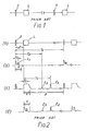
- Fig. 1 shows an example of composite pulse each consisting of a combination of a short pulse S and a long pulse L . It may not necessarily be required that the short pulses S be equal in number to the long pulses L or that the width of every short pulses be identical. The interval between the short and long pulses S and L is required to be equal to or longer than the width of the long pulse L .
- each composite pulse includes one short pulse S and one long pulse L .
- Fig. 2(a) shows the timing of transmission of the respective short and long pulses S and L .
- the pulse interval ⁇ T between the two pulses S and L is set to be a little longer than the width of the long pulse L .
- Figs 2(b) and 2(c) respectively show the video output signals from a short pulse receiver and a long pulse receiver, which respectively receive echo signals E1 for the short pulse S and E2 for the long pulse L . To simplify the explanation, delays at the receiver are neglected.
- the tine indicated by ⁇ in Fig. 2(c) represents the saturation time period of the long pulse receiver due to the leaking of the transmitted long pulse.
- a target is located at a short distance given by CT 1/2 (where T1 ⁇ T and C is the velocity of light) from the radar system, hereinafter called a "short-distance target".
- An echo signal from the short-distance target for the long pulse L cannot be detected by the long pulse receiver because it is received during the saturation time ⁇ .
- an echo signal E1 from the short-distance target for the short pulse S can be detected.
- the received echo signal E1 for the short pulse S is delayed for a pulse interval ⁇ T, and the echo signal received during the saturation time ⁇ for the long pulse L is replaced with the delayed received echo signal E1 to be combined with the echo video signal E2 for the long pulse.
- the short pulse video signal is selectively monitored during a time period indicated by H in Fig. 2(b) which is shorter than ⁇ T, while for the long-range monitoring the long pulse video signal is selected in a duration B shown in Fig. 2(c).
- the conventional composite pulse radar system still involves a material disadvantage if there is relatively large target which strongly reflects radio waves and is located at a distance of CT 2/2 (T2> ⁇ T).
- an echo signal E3 from the large target for the short pulse is received during the long-range monitoring period B in addition to the echo signal E2 for the long pulse, as shown in Figs. 2(c) and Fig. 2(d).
- the time interval ⁇ T between the short and long pulses could be lengthened or the respective frequencies of the long pulse L and the short pulse S could be made different from each other.
- the former method involves a disadvantage since it reduces the number of target hit times (or data rate), thereby lowering the probability of detecting a target, and the latter method has the disadvantage of broadening the bandwidth occupied by the radar, thereby impairing the effective use of radio waves.
- FR-A-1558734 describes a composite pulse radar system for receiving simultaneously signals originating from airborne targets at long and short distances.
- the system generates superimposed beams of pulses having different lengths.
- Each train of pulses consists of a long pulse and a short pulse. Interference signals arising from the ground and from rain are eliminated. Echoes from the long and short pulses are treated differently, the echoes from short pulses being passed through a wide bandfilter and delayed, and the echoes from the long pulses being passed through a narrow bandfilter.
- a composite pulse radar system of the kind defined hereinbefore at the beginning is characterised in that the interval of time between the short and long pulses of the transmitted composite pulses varies from transmitted composite pulse to transmitted composite pulse and in that the system comprises further: a correlating means correlating the resultant composite video signals for a plurality of successive cycles for cancelling in its correlated output signals the assynchronous interferences due to false images of transmitted short pulse received during the period of reception of the long echo video signals.
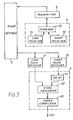
- the embodiment comprises a composite pulse generator 7 which generates such composite pulses that the interval between short and long pulses varies in each cycle, a transmitter 8, a radar antenna 9, a short pulse receiver 10 which receives an echo video signal for the short pulse (hereinafter called “short pulse video signal”), a long pulse receiver 11 which receives an echo video signal for the long pulse (hereinafter called “long pulse video signal”), and a video processing section 6 which combines the short and long pulse video signals and eliminates asynchronous interference.
- the composite pulse generator 7 includes a long pulse generator 71, a short pulse generator 72 and a combiner 73 which combines the outputs of the two generators 71 and 72 to generate a composite pulse.
- the short pulse video signal from the short pulse receiver 10 is delayed for ⁇ T by an delay element 61.
- a video exchanger 62 selects one of the video signals of the long pulse video signal from the long pulse receiver 11 and the delayed short pulse video signal from the delay element 61 to obtain composite video signal for the short and long pulses.
- the resultant video signal is correlated with the video signals which have been obtained throughout the past several periods (sweeps), so that the ones which are not sufficiently correlated with the resultant video signal are eliminated as interference.
- this correlation processing there is a process of extracting only those video signals that are located in the same position on the time axis throughout the past several cycles and of eliminating any false image that varies in its time position.
- Figs. 4(a), 4(b) and 4(c) show the timing of each transmission over three successive cycles.
- the interval between the short pulse S and the long pulse L is varied each cycle as ⁇ T1, ⁇ T2 and ⁇ T3, respectively.
- Figs. 4(d), 4(e) and 4(f) show combined video signal for the short and long pulses corresponding to the respective transmissions shown in Figs. 4(a), 4(b) and 4(c).
- the echo signal for the long pulse L which has been reflected from a target located at a distance of CT/2 (where T> ⁇ T1, ⁇ T2, ⁇ T3) is indicated by E2 with the echo signal (false image) for the short pulse being indicated by E3. Since the pulse interval between the short and long pulses S and L changes in each cycle, the echo signal E3 for the short pulse S appears in a different position in each cycle, while the echo signal E2 for the long pulse L appears in the same position. Therefore, if video signal correlation over several successive cycles is performed, the false image by the echo signals E3 can be individually eliminated.
- An example of output waveforms obtained by the correlator is shown in Fig. 4(g).
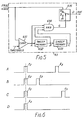
- Fig. 5 shows an exemplary construction of a sweep correlator 63 which correlates the video signals over several successive cycles.
- the combined video signal for the short and long pulses obtained by the video exchanger 62 is sent out to a comparator 631 in order to identify a desired target signal.
- the comparator 631 provides a "HIGH" level signal output when the combined video signal is above a certain level (or threshold).
- An output signal A of the comparator 631 is delayed by one sweep (or one interval between two transmitted composite pulses: T0 ) by a sweep memory 632 (hereinafter called a "delayed signal B"), and this delayed signal B is further delayed for the interval of T0 by the sweep memory 633 to generate an output C (hereinafter called a "delayed signal C ").
- the interval between the short and long pulses in the transmitted composite pulse is varied in each cycle. Therefore, if the received echo signal of each transmitted pulse from a reflecting target is monitored on the basis of the timing of a given reference transmitted pulse, the received echo signals for the reference transmitted pulse from various reflecting targets appear in the same time position in each cycle so long as the direction of the radar antenna is fixed. However, the received echo signals for other transmitted pulses appear in a different position on the time axis in accordance with the variation in the interval in each transmitted pulse. As a result, a received signal at a random timing in each cycle in relation to the timing of the reference transmitted pulse, or called “asynchronous received signal", can be detected and eliminated.
- the present invention can be effective irrespective of whether each of the intervals between the long pulses to be transmitted is equal or staggered.
- the number of short pulses is equal to that of long pulses.
- this invention is not limited thereto.
- the eliminating of radio interference between pulses can be achieved to the same extent as the above-mentioned case by the operation of correlating received video signals over successive cycles on the receiver side.
- this invention is arranged in such a manner that the interval between the short and long pulses in each composite pulse to be transmitted during one cycle is varied in each cycle and the asynchronous signals in the received video signals are eliminated by comparison of the received video signals without causing the problems of reduction in the number of target hits due to mere lengthening of the interval between short and long pulses or of the broadening of an occupied bandwidth due to the allocation of two frequencies for short and long pulses as practiced in conventional methods.
Landscapes
- Engineering & Computer Science (AREA)
- Radar, Positioning & Navigation (AREA)
- Remote Sensing (AREA)
- Computer Networks & Wireless Communication (AREA)
- Physics & Mathematics (AREA)
- General Physics & Mathematics (AREA)
- Radar Systems Or Details Thereof (AREA)
Description
- The present invention relates to a composite pulse radar system of the kind comprising: a pulse generator generating composite pulses having a short pulse and a long pulse with an interval between the short and long pulses, a pulse transmitter transmitting a plurality of said composite pulses generated by said pulse generator, in a given repeated cycle, a short pulse receiver and a long pulse receiver receiving respectively short echo video signals for the transmitted short pulse and long echo video signals for the transmitted long pulse, a delaying means for delaying at least the short echo video signal received in response to a given transmitted composite pulse, for a predetermined time equal to the interval between the transmission of the respective short and long pulse of said given transmitted composite pulse; and a combining means for combining the output signal of said delaying means and the long echo video signal, both corresponding to the said given transmitted composite pulse and for providing at its output a resultant composite video signal.
- A conventional pulse radar system employs a long transmitted pulse with a large pulse width because it increases the system gain and hence extends the maximum target detectable range. However, a large pulse width prolongs the saturation time in a radar receiver due to the leaking of the transmitted pulse which occurs shortly after transmission, and it thereby becomes impossible to detect a target located at a position within the range equivalent to the saturation time. This disadvantage leads to material deficiency in a radar system that particularly requires short-range coverage performance.
- In order to overcome this disadvantage, a short pulse has been used, in addition to the long pulse, for short-range coverage. It is transmitted shortly before the transmission of the long pulse. This system is known as a composite pulse radar system. Fig. 1 shows an example of composite pulse each consisting of a combination of a short pulse S and a long pulse L. It may not necessarily be required that the short pulses S be equal in number to the long pulses L or that the width of every short pulses be identical. The interval between the short and long pulses S and L is required to be equal to or longer than the width of the long pulse L.
- The relationship between transmission and reception in the conventional composite pulse radar system will now be described with reference to Fig. 2 which shows the case where each composite pulse includes one short pulse S and one long pulse L.
- Fig. 2(a) shows the timing of transmission of the respective short and long pulses S and L. The pulse interval ΔT between the two pulses S and L is set to be a little longer than the width of the long pulse L. Figs 2(b) and 2(c) respectively show the video output signals from a short pulse receiver and a long pulse receiver, which respectively receive echo signals E₁ for the short pulse S and E₂ for the long pulse L. To simplify the explanation, delays at the receiver are neglected. The tine indicated by τ in Fig. 2(c) represents the saturation time period of the long pulse receiver due to the leaking of the transmitted long pulse.
- It is now assumed that a target is located at a short distance given by CT1/2 (where T₁<T and C is the velocity of light) from the radar system, hereinafter called a "short-distance target". An echo signal from the short-distance target for the long pulse L cannot be detected by the long pulse receiver because it is received during the saturation time τ. On the other hand, an echo signal E₁ from the short-distance target for the short pulse S can be detected. As shown in Fig. 2(d), the received echo signal E₁ for the short pulse S is delayed for a pulse interval ΔT, and the echo signal received during the saturation time τ for the long pulse L is replaced with the delayed received echo signal E₁ to be combined with the echo video signal E₂ for the long pulse. For short-range monitoring the short pulse video signal is selectively monitored during a time period indicated by H in Fig. 2(b) which is shorter than ΔT, while for the long-range monitoring the long pulse video signal is selected in a duration B shown in Fig. 2(c). Thus the short-range detecting performance of the pulse radar is improved.
- However, the conventional composite pulse radar system still involves a material disadvantage if there is relatively large target which strongly reflects radio waves and is located at a distance of CT2/2 (T₂> ΔT). In this case, an echo signal E₃ from the large target for the short pulse is received during the long-range monitoring period B in addition to the echo signal E₂ for the long pulse, as shown in Figs. 2(c) and Fig. 2(d). To prevent this false signal the time interval ΔT between the short and long pulses could be lengthened or the respective frequencies of the long pulse L and the short pulse S could be made different from each other. However, the former method involves a disadvantage since it reduces the number of target hit times (or data rate), thereby lowering the probability of detecting a target, and the latter method has the disadvantage of broadening the bandwidth occupied by the radar, thereby impairing the effective use of radio waves.
- FR-A-1558734 describes a composite pulse radar system for receiving simultaneously signals originating from airborne targets at long and short distances. The system generates superimposed beams of pulses having different lengths. Each train of pulses consists of a long pulse and a short pulse. Interference signals arising from the ground and from rain are eliminated. Echoes from the long and short pulses are treated differently, the echoes from short pulses being passed through a wide bandfilter and delayed, and the echoes from the long pulses being passed through a narrow bandfilter.
- Accordingly, it is an object of this invention to provide a system in which any echo signal resulting from a short pulse is prevented from interferring with the reception of an echo signal resulting from long pulse without involving any reduction in the number of target hit times or broadening the occupied bandwidth.
- According to the present invention a composite pulse radar system of the kind defined hereinbefore at the beginning is characterised in that the interval of time between the short and long pulses of the transmitted composite pulses varies from transmitted composite pulse to transmitted composite pulse and in that the system comprises further: a correlating means correlating the resultant composite video signals for a plurality of successive cycles for cancelling in its correlated output signals the assynchronous interferences due to false images of transmitted short pulse received during the period of reception of the long echo video signals.
- The invention will now be described by way of example with reference to the accompanying drawings, in which:-
- Figs. 1 and 2 are diagrams showing an example of transmitted pulses according to a conventional composite pulse radar system and timing charts showing the time relationship between the transmitted pulses and the received echo signals, respectively;
- Fig. 3 is a block diagram of one preferred embodiment of this invention, showing an exemplary construction of the composite pulse radar system;
- Fig. 4 shows the time relationship between the transmission pulses and received echo signals according to the embodiment shown in Fig. 3;
- Fig. 5 is a block diagram of an example of the sweep correlator shown in Fig. 3; and
- Fig. 6 shows timing charts used for describing the operation of the correlator of Fig. 5.
- The preferred embodiment of this invention will be described hereinafter, which is in the case where the respective numbers of short pulses and long pulses are equally one.
- Referring to Fig. 3, the embodiment comprises a
composite pulse generator 7 which generates such composite pulses that the interval between short and long pulses varies in each cycle, a transmitter 8, a radar antenna 9, ashort pulse receiver 10 which receives an echo video signal for the short pulse (hereinafter called "short pulse video signal"), along pulse receiver 11 which receives an echo video signal for the long pulse (hereinafter called "long pulse video signal"), and a video processing section 6 which combines the short and long pulse video signals and eliminates asynchronous interference. In this embodiment thecomposite pulse generator 7 includes along pulse generator 71, ashort pulse generator 72 and acombiner 73 which combines the outputs of the twogenerators short pulse receiver 10 is delayed for ΔT by andelay element 61. Avideo exchanger 62 selects one of the video signals of the long pulse video signal from thelong pulse receiver 11 and the delayed short pulse video signal from thedelay element 61 to obtain composite video signal for the short and long pulses. The resultant video signal is correlated with the video signals which have been obtained throughout the past several periods (sweeps), so that the ones which are not sufficiently correlated with the resultant video signal are eliminated as interference. As an example of this correlation processing, there is a process of extracting only those video signals that are located in the same position on the time axis throughout the past several cycles and of eliminating any false image that varies in its time position. - The operation of eliminating the radio interference between pulses in accordance with this invention will be described with reference to Fig. 4. Figs. 4(a), 4(b) and 4(c) show the timing of each transmission over three successive cycles. The interval between the short pulse S and the long pulse L is varied each cycle as ΔT₁, ΔT₂ and ΔT₃, respectively. Figs. 4(d), 4(e) and 4(f) show combined video signal for the short and long pulses corresponding to the respective transmissions shown in Figs. 4(a), 4(b) and 4(c). In this figure, the echo signal for the long pulse L which has been reflected from a target located at a distance of CT/₂ (where T> ΔT₁, ΔT₂, ΔT₃) is indicated by E₂ with the echo signal (false image) for the short pulse being indicated by E₃. Since the pulse interval between the short and long pulses S and L changes in each cycle, the echo signal E₃ for the short pulse S appears in a different position in each cycle, while the echo signal E₂ for the long pulse L appears in the same position. Therefore, if video signal correlation over several successive cycles is performed, the false image by the echo signals E₃ can be individually eliminated. An example of output waveforms obtained by the correlator is shown in Fig. 4(g).
- Fig. 5 shows an exemplary construction of a
sweep correlator 63 which correlates the video signals over several successive cycles. The combined video signal for the short and long pulses obtained by thevideo exchanger 62 is sent out to acomparator 631 in order to identify a desired target signal. Thecomparator 631 provides a "HIGH" level signal output when the combined video signal is above a certain level (or threshold). An output signal A of thecomparator 631 is delayed by one sweep (or one interval between two transmitted composite pulses: T₀) by a sweep memory 632 (hereinafter called a "delayed signal B"), and this delayed signal B is further delayed for the interval of T₀ by thesweep memory 633 to generate an output C (hereinafter called a "delayed signal C"). These signals A, B and C are fed to anAND gate 634. Only when the signals A, B and C are simultaneously present does theAND gate 634 output a gate signal G which is fed to aswitch 635. Theswitch 635 is switched over to a terminal a by the gate signal G, and the combined video signal from thecombiner 62 is then provided as the output from thesweep correlator 63. On the other hand, when no gate signal G from theAND gate 634 is present, theswitch 635 is switched over to a terminal b and no output is generated from thesweep correlator 63. As shown in Fig. 6, only when there is a coincidence in time relationship between the received signal A, the signal B received in the previous sweep and the signal C received two sweeps previously, is theswitch 635 actuated and thus an output D produced as the target signal E₂. On the other hand, when the three signals do not coincide in time relationship, theswitch 635 is not actuated and no output is produced since the signal is judged to be an interference signal E₃ (or false image). - In the method of this invention, as described above, the interval between the short and long pulses in the transmitted composite pulse is varied in each cycle. Therefore, if the received echo signal of each transmitted pulse from a reflecting target is monitored on the basis of the timing of a given reference transmitted pulse, the received echo signals for the reference transmitted pulse from various reflecting targets appear in the same time position in each cycle so long as the direction of the radar antenna is fixed. However, the received echo signals for other transmitted pulses appear in a different position on the time axis in accordance with the variation in the interval in each transmitted pulse. As a result, a received signal at a random timing in each cycle in relation to the timing of the reference transmitted pulse, or called "asynchronous received signal", can be detected and eliminated.
- It is to be noted that the present invention can be effective irrespective of whether each of the intervals between the long pulses to be transmitted is equal or staggered. Furthermore, in this preferred embodiment, the number of short pulses is equal to that of long pulses. However, this invention is not limited thereto. In accordance with this invention, in a case where the number of short pulses differs from that of long pulses as exemplarily shown in Fig. 1, the eliminating of radio interference between pulses can be achieved to the same extent as the above-mentioned case by the operation of correlating received video signals over successive cycles on the receiver side.
- In another case where the frequencies of both short and long pulses are different, strong echo signals exceeding the isolation level of a filter for separating short and long pulses tends to cause interference between pulses. However, the invention of this application can be adapted to eliminate such interference as well.
- As described above, this invention is arranged in such a manner that the interval between the short and long pulses in each composite pulse to be transmitted during one cycle is varied in each cycle and the asynchronous signals in the received video signals are eliminated by comparison of the received video signals without causing the problems of reduction in the number of target hits due to mere lengthening of the interval between short and long pulses or of the broadening of an occupied bandwidth due to the allocation of two frequencies for short and long pulses as practiced in conventional methods.
Claims (7)
- Composite pulse radar system comprising: a pulse generator (7) generating composite pulses having a short pulse and a long pulse with an interval between the short and long pulses, a pulse transmitter (8) transmitting a plurality of said composite pulses generated by said pulse generator, in a given repeated cycle, a short pulse receiver (10) and a long pulse receiver (11) receiving respectively short echo video signals for the transmitted short pulse and long echo video signals for the transmitted long pulse, a delaying means (61) for delaying at least the short echo video signal received in response to a given transmitted composite pulse, for a predetermined time equal to the interval between the transmission of the respective short and long pulse of said given transmitted composite pulse; and a combining means (62) for combining the output signal of said delaying means (61) and the long echo video signal, both corresponding to the said given transmitted composite pulse and for providing at its output a resultant composite video signal, characterised in that the interval of time between the short and the long pulses of the transmitted composite pulses varies from transmitted composite pulse to transmitted composite pulse and in that the system comprises further:
a correlating means (63) correlating the resultant composite video signals for a plurality of successive repeated cycles for cancelling in its correlated output signals the asynchronous interferences due to false images of the transmitted short pulse received during the period of reception of the long echo video signals. - A composite pulse radar according to claim 1,
characterised in that the correlating means comprises:
a plurality of sweep memories (632, 633) connected in series which delay the output of said combining means (62) for a time equivalent to the repetition period of said repeated cycles;
an AND gate (634) which is supplied with at least one of the input and the output of said respective sweep memories (632, 633); and
a switching means (635) which produces the output of said combining means (62) only when the output of said AND gate (634) is present. - A composite pulse radar according to claim 1,
characterised in that each of said short and long pulses is a single pulse. - A composite pulse radar according to claim 1,
characterised in that the repeated cycle of said composite pulses is equal. - A composite pulse radar according to claim 1,
characterised in that the repeated cycle of said composite pulses is different. - A composite pulse radar according to claim 1,
characterised in that the carrier frequencies of said short and long pulses are different. - A composite pulse radar according to claim 2,
characterised in that the sweep memories (632, 633) connected in series includes a front stage sweep memory (632) and a rear stage sweep memory (633), the input and the output of said front stage sweep memory (632) as well as the output of the rear stage sweep memory (633) being fed to the input of said AND gate (634).
Applications Claiming Priority (2)
| Application Number | Priority Date | Filing Date | Title |
|---|---|---|---|
| JP256314/84 | 1984-12-04 | ||
| JP59256314A JPS61133885A (en) | 1984-12-04 | 1984-12-04 | Inter-pulse interference removing system for composite pulse radar |
Publications (3)
| Publication Number | Publication Date |
|---|---|
| EP0184424A2 EP0184424A2 (en) | 1986-06-11 |
| EP0184424A3 EP0184424A3 (en) | 1987-09-02 |
| EP0184424B1 true EP0184424B1 (en) | 1991-07-31 |
Family
ID=17290941
Family Applications (1)
| Application Number | Title | Priority Date | Filing Date |
|---|---|---|---|
| EP19850308782 Expired EP0184424B1 (en) | 1984-12-04 | 1985-12-03 | Composite pulse radar system having means for eliminating interference between pulses |
Country Status (2)
| Country | Link |
|---|---|
| EP (1) | EP0184424B1 (en) |
| JP (1) | JPS61133885A (en) |
Cited By (1)
| Publication number | Priority date | Publication date | Assignee | Title |
|---|---|---|---|---|
| US7773028B2 (en) | 2006-12-06 | 2010-08-10 | Raytheon Company | Method and system for concatenation of radar pulses |
Families Citing this family (20)
| Publication number | Priority date | Publication date | Assignee | Title |
|---|---|---|---|---|
| JPH01214787A (en) * | 1988-02-23 | 1989-08-29 | Furuno Electric Co Ltd | Radar and similar apparatus |
| DE4105977A1 (en) * | 1990-03-07 | 1991-09-12 | Telefunken Systemtechnik | SIGNAL PROCESSING METHOD AND SIGNAL PROCESSING ARRANGEMENT FOR A PULSE RADAR SYSTEM |
| DE10059673A1 (en) * | 2000-12-01 | 2002-06-06 | Bosch Gmbh Robert | Pulse radar method as well as pulse radar sensor and system |
| JP2006078284A (en) * | 2004-09-08 | 2006-03-23 | Fujitsu Ltd | Pulse radar equipment |
| US7589666B2 (en) | 2004-12-30 | 2009-09-15 | Vaisala, Inc. | System and method for processing data in weather radar |
| US7583222B2 (en) | 2005-08-26 | 2009-09-01 | Vaisala Oyj | Method for using pulse compression in weather radar |
| US20070229348A1 (en) * | 2005-12-23 | 2007-10-04 | Vaisala, Inc. | Frequency based hybrid pulse for detection of meteorological phenomena in radar systems |
| US7495598B2 (en) * | 2006-04-04 | 2009-02-24 | Honeywell International Inc. | Methods and systems for avoidance of partial pulse interference in radar |
| GB0717031D0 (en) * | 2007-08-31 | 2007-10-10 | Raymarine Uk Ltd | Digital radar or sonar apparatus |
| JP2011027587A (en) * | 2009-07-27 | 2011-02-10 | Japan Radio Co Ltd | Radar device |
| JP5697877B2 (en) * | 2010-02-01 | 2015-04-08 | 古野電気株式会社 | Transmission device, transmission method, target detection device, and target detection method |
| JP2012103196A (en) * | 2010-11-12 | 2012-05-31 | Japan Radio Co Ltd | Radar device |
| JP6029287B2 (en) * | 2012-02-22 | 2016-11-24 | 大学共同利用機関法人情報・システム研究機構 | Distance measuring method and radar device |
| JP6037625B2 (en) * | 2012-03-12 | 2016-12-07 | 東京計器株式会社 | Radar interference canceling apparatus and radar interference canceling method |
| JP6184220B2 (en) * | 2013-07-24 | 2017-08-23 | 三菱電機株式会社 | Radar system, radar apparatus and radar signal processing apparatus |
| JP6299112B2 (en) * | 2013-08-28 | 2018-03-28 | 日本電気株式会社 | Radar apparatus, radar signal processing method and program |
| CN107250837B (en) | 2015-02-25 | 2020-12-22 | 古河电气工业株式会社 | Radar device and object detection method of radar device |
| CN106950545B (en) * | 2017-02-22 | 2020-08-07 | 武汉滨湖电子有限责任公司 | Dual-frequency transmitting mode and clutter suppression method based on dual-frequency real-time processing |
| EP3839560B1 (en) | 2019-12-19 | 2023-03-01 | UTC Fire & Security EMEA BVBA | Radar presence sensor device |
| CN113156396B (en) * | 2021-04-30 | 2023-07-21 | 深圳煜炜光学科技有限公司 | Method and device for optimizing influence of interference source on laser radar |
Family Cites Families (4)
| Publication number | Priority date | Publication date | Assignee | Title |
|---|---|---|---|---|
| BE563351A (en) * | 1956-12-20 | |||
| NL6803758A (en) * | 1967-03-16 | 1968-09-17 | ||
| NL6712495A (en) * | 1967-09-13 | 1969-03-17 | ||
| GB1424026A (en) * | 1973-11-13 | 1976-02-04 | Marconi Co Ltd | Radar systems |
-
1984
- 1984-12-04 JP JP59256314A patent/JPS61133885A/en active Pending
-
1985
- 1985-12-03 EP EP19850308782 patent/EP0184424B1/en not_active Expired
Cited By (1)
| Publication number | Priority date | Publication date | Assignee | Title |
|---|---|---|---|---|
| US7773028B2 (en) | 2006-12-06 | 2010-08-10 | Raytheon Company | Method and system for concatenation of radar pulses |
Also Published As
| Publication number | Publication date |
|---|---|
| EP0184424A3 (en) | 1987-09-02 |
| EP0184424A2 (en) | 1986-06-11 |
| JPS61133885A (en) | 1986-06-21 |
Similar Documents
| Publication | Publication Date | Title |
|---|---|---|
| EP0184424A2 (en) | Composite pulse radar system having means for eliminating interference between pulses | |
| EP2821808B1 (en) | Radar apparatus and radar signal processing method | |
| US5081457A (en) | Apparatus for reducing synchronous fruit in tcas surveillance systems | |
| US6271786B1 (en) | Random noise radar target detection device | |
| CA2255890C (en) | Virtual noise radar waveform for reduced radar detectability | |
| CA2201262C (en) | Synthetic aperture radar | |
| EP1512988A1 (en) | Secondary surveillance radar system, ground equipment for use therein, and response signal checking method applied thereto | |
| US5057845A (en) | Radar apparatus employing different kinds of pulses | |
| CA2375270C (en) | Radar apparatus | |
| KR102189108B1 (en) | Pulse radar system and how it works | |
| US7755538B2 (en) | Radar apparatus | |
| JP3160292B2 (en) | Radar equipment | |
| GB2134741A (en) | Radar apparatus | |
| GB2088667A (en) | A radar system employing pulses of different types | |
| JPH0666930A (en) | Radar apparatus | |
| JP2656097B2 (en) | Radar equipment | |
| JP3573430B2 (en) | Radar equipment | |
| JP3335778B2 (en) | Radar equipment | |
| JP2770814B2 (en) | Active sonar device | |
| JPS58189570A (en) | Interference eliminating system of radar | |
| US4008471A (en) | Correlator to reduce bin straddle in a collision avoidance system | |
| JP2652950B2 (en) | Pulse compression radar device | |
| JPH11142504A (en) | Pulse transmission / reception radar device | |
| JPS5816477B2 (en) | radar device | |
| JPH10300841A (en) | Active sonar device |
Legal Events
| Date | Code | Title | Description |
|---|---|---|---|
| PUAI | Public reference made under article 153(3) epc to a published international application that has entered the european phase |
Free format text: ORIGINAL CODE: 0009012 |
|
| 17P | Request for examination filed |
Effective date: 19851211 |
|
| AK | Designated contracting states |
Kind code of ref document: A2 Designated state(s): FR GB NL |
|
| PUAL | Search report despatched |
Free format text: ORIGINAL CODE: 0009013 |
|
| AK | Designated contracting states |
Kind code of ref document: A3 Designated state(s): FR GB NL |
|
| 17Q | First examination report despatched |
Effective date: 19890703 |
|
| GRAA | (expected) grant |
Free format text: ORIGINAL CODE: 0009210 |
|
| AK | Designated contracting states |
Kind code of ref document: B1 Designated state(s): FR GB NL |
|
| ET | Fr: translation filed | ||
| PLBI | Opposition filed |
Free format text: ORIGINAL CODE: 0009260 |
|
| 26 | Opposition filed |
Opponent name: SIEMENS AKTIENGESELLSCHAFT, BERLIN UND MUENCHEN Effective date: 19920430 |
|
| NLR1 | Nl: opposition has been filed with the epo |
Opponent name: SIEMENS AG. |
|
| PLBN | Opposition rejected |
Free format text: ORIGINAL CODE: 0009273 |
|
| STAA | Information on the status of an ep patent application or granted ep patent |
Free format text: STATUS: OPPOSITION REJECTED |
|
| 27O | Opposition rejected |
Effective date: 19940401 |
|
| NLR2 | Nl: decision of opposition | ||
| REG | Reference to a national code |
Ref country code: GB Ref legal event code: IF02 |
|
| PGFP | Annual fee paid to national office [announced via postgrant information from national office to epo] |
Ref country code: GB Payment date: 20041201 Year of fee payment: 20 |
|
| PGFP | Annual fee paid to national office [announced via postgrant information from national office to epo] |
Ref country code: NL Payment date: 20041205 Year of fee payment: 20 |
|
| PGFP | Annual fee paid to national office [announced via postgrant information from national office to epo] |
Ref country code: FR Payment date: 20041208 Year of fee payment: 20 |
|
| PG25 | Lapsed in a contracting state [announced via postgrant information from national office to epo] |
Ref country code: GB Free format text: LAPSE BECAUSE OF EXPIRATION OF PROTECTION Effective date: 20051202 |
|
| PG25 | Lapsed in a contracting state [announced via postgrant information from national office to epo] |
Ref country code: NL Free format text: LAPSE BECAUSE OF EXPIRATION OF PROTECTION Effective date: 20051203 |
|
| REG | Reference to a national code |
Ref country code: GB Ref legal event code: PE20 |
|
| NLV7 | Nl: ceased due to reaching the maximum lifetime of a patent |
Effective date: 20051203 |