EP0184344A1 - Steam generator tube support - Google Patents
Steam generator tube support Download PDFInfo
- Publication number
- EP0184344A1 EP0184344A1 EP85308235A EP85308235A EP0184344A1 EP 0184344 A1 EP0184344 A1 EP 0184344A1 EP 85308235 A EP85308235 A EP 85308235A EP 85308235 A EP85308235 A EP 85308235A EP 0184344 A1 EP0184344 A1 EP 0184344A1
- Authority
- EP
- European Patent Office
- Prior art keywords
- tube
- support plate
- tubes
- lands
- holes
- Prior art date
- Legal status (The legal status is an assumption and is not a legal conclusion. Google has not performed a legal analysis and makes no representation as to the accuracy of the status listed.)
- Granted
Links
Images

Classifications
-
- F—MECHANICAL ENGINEERING; LIGHTING; HEATING; WEAPONS; BLASTING
- F28—HEAT EXCHANGE IN GENERAL
- F28F—DETAILS OF HEAT-EXCHANGE AND HEAT-TRANSFER APPARATUS, OF GENERAL APPLICATION
- F28F9/00—Casings; Header boxes; Auxiliary supports for elements; Auxiliary members within casings
- F28F9/007—Auxiliary supports for elements
- F28F9/013—Auxiliary supports for elements for tubes or tube-assemblies
- F28F9/0135—Auxiliary supports for elements for tubes or tube-assemblies formed by grids having only one tube per closed grid opening
-
- Y—GENERAL TAGGING OF NEW TECHNOLOGICAL DEVELOPMENTS; GENERAL TAGGING OF CROSS-SECTIONAL TECHNOLOGIES SPANNING OVER SEVERAL SECTIONS OF THE IPC; TECHNICAL SUBJECTS COVERED BY FORMER USPC CROSS-REFERENCE ART COLLECTIONS [XRACs] AND DIGESTS
- Y10—TECHNICAL SUBJECTS COVERED BY FORMER USPC
- Y10S—TECHNICAL SUBJECTS COVERED BY FORMER USPC CROSS-REFERENCE ART COLLECTIONS [XRACs] AND DIGESTS
- Y10S165/00—Heat exchange
- Y10S165/355—Heat exchange having separate flow passage for two distinct fluids
- Y10S165/40—Shell enclosed conduit assembly
- Y10S165/401—Shell enclosed conduit assembly including tube support or shell-side flow director
- Y10S165/416—Extending transverse of shell, e.g. fin, baffle
Definitions
- This invention relates to apparatus for supporting the tubes of a nuclear steam generator to inhibit vibration and, more particularly, to such apparatus that permits the ready insertion of the tubes, while providing improved support and extended life of the tubes.
- tube support plates which have tube holes disposed therethrough, each for receiving a tube.
- the load handling capability of the tube support plate is dependent upon its thickness and, in turn, upon the area of that section taken between the tube openings.
- Tube support plates of the prior art have been thickened to increase their load handling capacity. However, the ease of inserting the tubes through their corresponding openings is related to the thickness of the tube support plate.
- tube support plate increases, the ease of inserting the tubes therethrough decreases, thus necessitating an increase in the diameter of the tube holes and, in particular, the clearances between the tube holes and the tubes.
- increasing the clearances has a direct, negative effect on tube vibration and the expected life of the tubes. If the tubes are permitted to vibrate their exterior surfaces will begin to wear and scar. Eventually, tube vibration will cause wear through the walls of the tubes permitting the primary water circulating therethrough to leak into the secondary side of the steam generator and eventually to the turbine generator.
- Tube support plates of the prior art are also subject to dry out or vapor blanketing at the area of contact between the tubes and the tube support plate. Contaminants in the secondary water tend to collect at the contact areas between the tubes and the tube support plate and the contaminants buildup at the contact areas corrode and weaken the tube walls.
- the contact areas between the tubes and the tube support plate tend to be hot with respect to the surrounding environment, noting the direct contact of the support plate with the tubes and the high temperature primary water passing therethrough.
- the secondary water circulating in the steam generator tends to dissipate this heat if it is permitted to flow directly about the contact areas.
- fine particles of magnetite formed at the relatively high temperatures within the feedwater and circulating secondary water tend to collect and buildup sludge patches about the tube openings and, in particular, the contact areas, thus preventing the secondary water direct access to the contact areas and the dissipation of heat therefrom. As the sludge patches buildup, heat removal at the contact areas is prevented thus leading to dry out and" corrosion of the contact areas.
- the present invention resides in a tube support plate for supporting a plurality of tubes in a nuclear steam generator, said support plate having a plurality of holes arranged in a given array, each of said holes having an axis, an interior surface and a plurality of lands projecting radially inwardly from said interior surface and having contact surfaces at their inner ends for supporting said tubes, wherein said lands are tapered at least at one of their ends so as to form a conical guide structure from said interior surface to said contact surface thereby facilitating the insertion of a tube through said hole.
- a nuclear steam generator 10 is shown in Figure 1 of the attached drawings, as comprising a bundle of a large number of vertically orientated U-shaped tubes 30.
- the tubes 30 are disposed in a lower, cylindrically shaped shell 12 of the steam generator 10, whose bottom end is associated with a primary coolant plenum or channel head 16, typically of a hemispherical configuration as shown in Figure 1.
- the channel head 16 is divided by a partition 22 into a first half typically known as a hot leg 18, and a second half typically known as a cold leg 20.
- High- temperature primary water from a nuclear reactor is introduced into the steam generator 10, through a primary inlet 24 into the hot leg 18.
- the primary water passes from the hot leg 18 into the exposed openings of the plurality of U-shaped tubes 30, flows through the tubes 30 to be introduced into the cold leg 20, and finally, exits from the steam generator 10 through a primary outlet 26.
- Opposite ends of the U-shaped tubes 30 are mounted within a tube sheet 28 in communication with the hot leg 18 and the cold leg 20, respectively.
- a wrapper 14 surrounds the bundle of U-shaped tubes 30.
- a part of the wrapper 14 is broken away to show one of a plurality of tube support plates 32. It is understood that the other tube support plates 32 are disposed above the illustrated plate and in parallel relationship thereto to support the bundle of tubes 30 in a manner to inhibit vibration induced by the secondary water circulating through the steam generator 10.
- the tube support.plate 32 is more fully shown in Figures 2, 5 and 6.
- the tube support plate 32 includes a plurality of tube holes 34 disposed at the intersecting points of a regular grid formed by x and y lines disposed perpendicular to each other.
- Each tube hole 34 is separated from an adjacent tube hole 34, whether disposed along an x or y line, by a ligament 38 of substantially uniform cross-sectional area.
- the ligaments 38 are aligned with the x and y lines of the regular grid to provide improved load handling capability for withstanding seismic loadings.
- the ligaments 38 are aligned of each other to form columns running parallel to the x and y lines of the grid, thus providing a tube support structure of improved strength as compared with plates with non-aligned ligaments.
- Each tube hole 34 has a plurality of lobes 40a, b, c and d separated from each other by a like number of lands 36a, b, c and d.
- Each land 36 extends from an inner surface 37 toward a central axis of the hole 34 and presents a generally flat contact area 42 facing the hole axis.
- Each of the lands 36a, b, c and d has its own contact area 42a, b, c or d, respectively.
- the contact areas 42 are those portions of the lands 36 making contact with the tube 30, which is shown in dotted lines in Figures 5 and 6.
- each tube hole 34 has a major or enlarged portion 34a and a minor or constricted portion 34c, separated by a transition or tapered portion 34b.
- the lands 36 are removed from the enlarged portion 34a of the tube holes 34 and extend the length of the constricted portion 34c as taken along the hole axis.
- Each land 36 terminates at its top-most end with its tapered portion 34b.
- the tube support plate 32 is disposed so that the enlarged portion 34a is aligned toward the top of the steam generator 10. Noting that the water circulates upwardly through the tube holes 34 of the support plate 32, a further embodiment of this invention contemplates that the orientation of the tube support plate 32 be reversed and the enlarged portion 34a be disposed downwardly to the end that water circulation through the tube holes 34 and, thus, sludge removal may be improved.
- the outer diameter of the tubes 30 is of substantially the same inner diameter as presented by the contact areas 42 of the lands 36, whereby the diametral clearances between the tubes 30 and the contact areas 42 of the lands 36 may be significantly reduced. Thus, the degree of tube vibration is significantly reduced and tube life improved.
- the first step is a drilling operation with a stepped-diameter drill.
- An upper portion of the drill is of a relatively large diameter corresponding to the enlarged portion of 34a of the tube hole 34, and a lower portion is of reduced diameter corresponding to the constricted portion 34c.
- a taper exists between the upper and lower portions of the drill.
- the upper portion of the drill is .923/.918 inches in diameter and the lower portion of the drill is .760/.758 inches in diameter; a 3% inch taper exists between the upper and lower drill portions.
- the first, drilling operation forms an initial opening 34' in the tube support plate 32 as shown in Figures 3 and 4.
- the upper portion of the drill makes an opening 34'a of a relatively large diameter, whereas the lower portion of the drill makes an opening 34'c of a lesser diameter.
- the openings 34'a and 34'c are separated by a tapered portion 34'b.
- the upper, larger diameter drill removes a significant amount of material, which would normally have to be removed by a subsequent operation, but leaves intact the straight, load carrying portion of the ligaments 38 separating the tube holes 34.
- the holes 34 are broached, whereby the lobes 40a, b, c and d are formed with the lands 36a, b, c and d disposed therebetween.
- the broach may be dimensioned to provide openings 34 having a diagonal measurement of 1.098/1.094 inches and a side measurement of .762/.760 inches.
- the contact areas 42a, b, c and d are finished by wire brushing.
- the length of the lands 36 as taken along the hole axis and their contact areas 42 is reduced.
- the reduced length of the lands 36, as well as the use of the tapered portions 34b, facilitates the ease with which tubes 30 may be disposed within the tube holes 34, as explained above.
- the ease of tube insertability is not provided at the expense of the structural strength of the tube support plate 32, which is maintained at a relatively large thickness as taken along the hole axis, whereby the loading capacity as dependent on the cross-sectional area of the ligaments 38 is kept relatively great.
- the reduction in the land length permits a decrease of the diametral clearances between the tubes and the holes of the tube support plate, whereby tube vibration is decreased and expected tube life increased.
- the reduction of the land length confines the stream or flow of secondary water through each of the tube holes, whereby the flow region downstream or below the lands, as seen in Figure 6, is confined and the velocity of the water flow about the contact areas between the tubes and the tube support plate is increased, thus preventing the buildup of sludge deposition and vapor blanketing; as a result, tube corrosion is reduced and tube life further extended.
Landscapes
- Engineering & Computer Science (AREA)
- Physics & Mathematics (AREA)
- Thermal Sciences (AREA)
- Mechanical Engineering (AREA)
- General Engineering & Computer Science (AREA)
- Heat-Exchange Devices With Radiators And Conduit Assemblies (AREA)
- Supports For Pipes And Cables (AREA)
- Vibration Prevention Devices (AREA)
- Monitoring And Testing Of Nuclear Reactors (AREA)
- Vessels And Coating Films For Discharge Lamps (AREA)
- Unwinding Webs (AREA)
Abstract
Description
- This invention relates to apparatus for supporting the tubes of a nuclear steam generator to inhibit vibration and, more particularly, to such apparatus that permits the ready insertion of the tubes, while providing improved support and extended life of the tubes.
- In such steam generators heat exchanger tubes are supported by tube support plates which have tube holes disposed therethrough, each for receiving a tube. The secondary water circulating within the steam generator and possibly faulted conditions of feedline and steamline breaks impose a load on the tube support plate. The load handling capability of the tube support plate is dependent upon its thickness and, in turn, upon the area of that section taken between the tube openings. Tube support plates of the prior art have been thickened to increase their load handling capacity. However, the ease of inserting the tubes through their corresponding openings is related to the thickness of the tube support plate. As the thickness of tube support plate increases, the ease of inserting the tubes therethrough decreases, thus necessitating an increase in the diameter of the tube holes and, in particular, the clearances between the tube holes and the tubes. However, increasing the clearances has a direct, negative effect on tube vibration and the expected life of the tubes. If the tubes are permitted to vibrate their exterior surfaces will begin to wear and scar. Eventually, tube vibration will cause wear through the walls of the tubes permitting the primary water circulating therethrough to leak into the secondary side of the steam generator and eventually to the turbine generator.
- Tube support plates of the prior art are also subject to dry out or vapor blanketing at the area of contact between the tubes and the tube support plate. Contaminants in the secondary water tend to collect at the contact areas between the tubes and the tube support plate and the contaminants buildup at the contact areas corrode and weaken the tube walls.
- The contact areas between the tubes and the tube support plate tend to be hot with respect to the surrounding environment, noting the direct contact of the support plate with the tubes and the high temperature primary water passing therethrough. The secondary water circulating in the steam generator tends to dissipate this heat if it is permitted to flow directly about the contact areas. However, fine particles of magnetite formed at the relatively high temperatures within the feedwater and circulating secondary water tend to collect and buildup sludge patches about the tube openings and, in particular, the contact areas, thus preventing the secondary water direct access to the contact areas and the dissipation of heat therefrom. As the sludge patches buildup, heat removal at the contact areas is prevented thus leading to dry out and" corrosion of the contact areas.
- It is therefore the principal object of this invention to avoid the corrosion of steam generator tubes and, thereby, improve steam generator life and furthermore, to improve the insertability of tubes through the support plate.
- With this object in view, the present invention resides in a tube support plate for supporting a plurality of tubes in a nuclear steam generator, said support plate having a plurality of holes arranged in a given array, each of said holes having an axis, an interior surface and a plurality of lands projecting radially inwardly from said interior surface and having contact surfaces at their inner ends for supporting said tubes, wherein said lands are tapered at least at one of their ends so as to form a conical guide structure from said interior surface to said contact surface thereby facilitating the insertion of a tube through said hole.
- The invention will become more readily apparent from the following description of a preferred embodiment thereof shown, by way of example only, in the accompanying drawings, wherein:
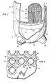
- Figure 1 is a perspective view of a nuclear steam generator including a tube support plate in accordance with the teachings of this invention;
- Figure 2 is a plan, partial view of the tube support plate as generally shown in Figure 1; and
- Figures 3 and 5 are respectively a plan view of a tube hole through the tube support plate in an intermediate stage of manufacture and a plan view of a tube hole as completed, whereas, Figures 4 and 6 are sectioned views taken along lines 4-4 and 6-6 of Figures 3 and 5, respectively.
- A
nuclear steam generator 10 is shown in Figure 1 of the attached drawings, as comprising a bundle of a large number of vertically orientatedU-shaped tubes 30. Thetubes 30 are disposed in a lower, cylindricallyshaped shell 12 of thesteam generator 10, whose bottom end is associated with a primary coolant plenum orchannel head 16, typically of a hemispherical configuration as shown in Figure 1. Thechannel head 16 is divided by apartition 22 into a first half typically known as ahot leg 18, and a second half typically known as acold leg 20. High- temperature primary water from a nuclear reactor is introduced into thesteam generator 10, through aprimary inlet 24 into thehot leg 18. The primary water passes from thehot leg 18 into the exposed openings of the plurality ofU-shaped tubes 30, flows through thetubes 30 to be introduced into thecold leg 20, and finally, exits from thesteam generator 10 through aprimary outlet 26. - Opposite ends of the
U-shaped tubes 30 are mounted within atube sheet 28 in communication with thehot leg 18 and thecold leg 20, respectively. Awrapper 14 surrounds the bundle ofU-shaped tubes 30. In Figure 1, a part of thewrapper 14 is broken away to show one of a plurality oftube support plates 32. It is understood that the othertube support plates 32 are disposed above the illustrated plate and in parallel relationship thereto to support the bundle oftubes 30 in a manner to inhibit vibration induced by the secondary water circulating through thesteam generator 10. - The
tube support.plate 32, is more fully shown in Figures 2, 5 and 6. Thetube support plate 32 includes a plurality oftube holes 34 disposed at the intersecting points of a regular grid formed by x and y lines disposed perpendicular to each other. Eachtube hole 34 is separated from anadjacent tube hole 34, whether disposed along an x or y line, by aligament 38 of substantially uniform cross-sectional area. As illustrated in Figure 2, theligaments 38 are aligned with the x and y lines of the regular grid to provide improved load handling capability for withstanding seismic loadings..In particular, theligaments 38 are aligned of each other to form columns running parallel to the x and y lines of the grid, thus providing a tube support structure of improved strength as compared with plates with non-aligned ligaments. - Each
tube hole 34 has a plurality oflobes 40a, b, c and d separated from each other by a like number oflands 36a, b, c and d. Each land 36 extends from aninner surface 37 toward a central axis of thehole 34 and presents a generally flat contact area 42 facing the hole axis. Each of thelands 36a, b, c and d has its own contact area 42a, b, c or d, respectively. The contact areas 42 are those portions of the lands 36 making contact with thetube 30, which is shown in dotted lines in Figures 5 and 6. - As best illustrated in Figure 6, each
tube hole 34 has a major or enlarged portion 34a and a minor or constrictedportion 34c, separated by a transition or taperedportion 34b. The lands 36 are removed from the enlarged portion 34a of thetube holes 34 and extend the length of theconstricted portion 34c as taken along the hole axis. Each land 36 terminates at its top-most end with itstapered portion 34b. Thus as shown in dotted lines in Figure 6, it is seen that as a leading end of atube 30 is inserted into the enlarged portion 34a, it engages thetapered portions 34b of the lands 36, thus directing thetube 30 into and through the restrictedportion 34c. In the embodiment shown in Figure 6, thetube support plate 32 is disposed so that the enlarged portion 34a is aligned toward the top of thesteam generator 10. Noting that the water circulates upwardly through thetube holes 34 of thesupport plate 32, a further embodiment of this invention contemplates that the orientation of thetube support plate 32 be reversed and the enlarged portion 34a be disposed downwardly to the end that water circulation through thetube holes 34 and, thus, sludge removal may be improved. As illustrated in Figures 2, 5 and 6, the outer diameter of thetubes 30 is of substantially the same inner diameter as presented by the contact areas 42 of the lands 36, whereby the diametral clearances between thetubes 30 and the contact areas 42 of the lands 36 may be significantly reduced. Thus, the degree of tube vibration is significantly reduced and tube life improved. - Referring now to Figures 3, 4, 5 and 6, a preferred method of forming the
tube holes 34 within thetube support plate 32 will be described. The first step is a drilling operation with a stepped-diameter drill. An upper portion of the drill is of a relatively large diameter corresponding to the enlarged portion of 34a of thetube hole 34, and a lower portion is of reduced diameter corresponding to theconstricted portion 34c. A taper exists between the upper and lower portions of the drill. In an illustrative embodiment of this invention, the upper portion of the drill is .923/.918 inches in diameter and the lower portion of the drill is .760/.758 inches in diameter; a 3% inch taper exists between the upper and lower drill portions. The first, drilling operation forms an initial opening 34' in thetube support plate 32 as shown in Figures 3 and 4. The upper portion of the drill makes an opening 34'a of a relatively large diameter, whereas the lower portion of the drill makes an opening 34'c of a lesser diameter. The openings 34'a and 34'c are separated by a tapered portion 34'b. The upper, larger diameter drill removes a significant amount of material, which would normally have to be removed by a subsequent operation, but leaves intact the straight, load carrying portion of theligaments 38 separating thetube holes 34. Next, theholes 34 are broached, whereby thelobes 40a, b, c and d are formed with thelands 36a, b, c and d disposed therebetween. In an illustrative embodiment of this invention, the broach may be dimensioned to provideopenings 34 having a diagonal measurement of 1.098/1.094 inches and a side measurement of .762/.760 inches. Finally, the contact areas 42a, b, c and d are finished by wire brushing. - Thus there has been shown a new and improved tube support plate that overcomes the significant problems of the prior art. First, the length of the lands 36 as taken along the hole axis and their contact areas 42 is reduced. The reduced length of the lands 36, as well as the use of the
tapered portions 34b, facilitates the ease with whichtubes 30 may be disposed within thetube holes 34, as explained above. The ease of tube insertability is not provided at the expense of the structural strength of thetube support plate 32, which is maintained at a relatively large thickness as taken along the hole axis, whereby the loading capacity as dependent on the cross-sectional area of theligaments 38 is kept relatively great. Further, the reduction in the land length permits a decrease of the diametral clearances between the tubes and the holes of the tube support plate, whereby tube vibration is decreased and expected tube life increased. As an additional benefit, the reduction of the land length confines the stream or flow of secondary water through each of the tube holes, whereby the flow region downstream or below the lands, as seen in Figure 6, is confined and the velocity of the water flow about the contact areas between the tubes and the tube support plate is increased, thus preventing the buildup of sludge deposition and vapor blanketing; as a result, tube corrosion is reduced and tube life further extended.
Claims (4)
Applications Claiming Priority (2)
| Application Number | Priority Date | Filing Date | Title |
|---|---|---|---|
| US670773 | 1984-11-13 | ||
| US06/670,773 US4709756A (en) | 1984-11-13 | 1984-11-13 | Steam generator tube support |
Publications (2)
| Publication Number | Publication Date |
|---|---|
| EP0184344A1 true EP0184344A1 (en) | 1986-06-11 |
| EP0184344B1 EP0184344B1 (en) | 1988-06-08 |
Family
ID=24691809
Family Applications (1)
| Application Number | Title | Priority Date | Filing Date |
|---|---|---|---|
| EP85308235A Expired EP0184344B1 (en) | 1984-11-13 | 1985-11-13 | Steam generator tube support |
Country Status (7)
| Country | Link |
|---|---|
| US (1) | US4709756A (en) |
| EP (1) | EP0184344B1 (en) |
| JP (1) | JPH0663712B2 (en) |
| CN (1) | CN85107967A (en) |
| CA (1) | CA1245120A (en) |
| DE (1) | DE3563265D1 (en) |
| ES (1) | ES296955Y (en) |
Cited By (2)
| Publication number | Priority date | Publication date | Assignee | Title |
|---|---|---|---|---|
| EP2123977A4 (en) * | 2007-02-27 | 2015-04-08 | Mitsubishi Heavy Ind Ltd | PIPE SUPPORT PLATE OF A STEAM GENERATOR |
| EP4242571A1 (en) * | 2022-03-09 | 2023-09-13 | Carrier Corporation | Non-metallic baffle for heat exchanger |
Families Citing this family (17)
| Publication number | Priority date | Publication date | Assignee | Title |
|---|---|---|---|---|
| DE69003404T3 (en) * | 1989-02-10 | 1997-05-15 | Mitsubishi Heavy Ind Ltd | Multi-tube type heat exchanger. |
| US6167295A (en) * | 1991-01-28 | 2000-12-26 | Radionics, Inc. | Optical and computer graphic stereotactic localizer |
| US5673654A (en) * | 1994-06-30 | 1997-10-07 | Aalborg Marine Boilers A/S | Marine boiler |
| DE29516927U1 (en) * | 1995-10-26 | 1996-02-01 | SGL Technik GmbH, 86405 Meitingen | Pipe for heat exchangers with vortex-generating current disturbance elements |
| US6059022A (en) * | 1997-02-14 | 2000-05-09 | Westinghouse Electric Company Llc | Steam generation with tube support |
| US6498827B1 (en) * | 1999-11-01 | 2002-12-24 | Babcock & Wilcox Canada, Ltd. | Heat exchanger tube support structure |
| US7120218B2 (en) * | 2002-09-25 | 2006-10-10 | Westinghouse Electric Co, Llc | Method for calibrating steam generator water level measurement |
| US6914955B2 (en) * | 2002-10-31 | 2005-07-05 | Babcock & Wilcox Canada Ltd. | Heat exchanger tube support structure |
| JP2005221118A (en) * | 2004-02-04 | 2005-08-18 | Japan Steel Works Ltd:The | Multi-tube heat exchanger |
| JP2007271157A (en) | 2006-03-31 | 2007-10-18 | Mitsubishi Heavy Ind Ltd | Support structure for heat transfer tube |
| US7506684B2 (en) * | 2007-06-20 | 2009-03-24 | Exxonmobil Research & Engineering Company | Anti-vibration tube support with locking assembly |
| US9683732B2 (en) * | 2011-10-13 | 2017-06-20 | Westinghouse Electric Company | Anti-clogging steam generator tube bundle |
| CN103868049B (en) * | 2012-12-13 | 2016-06-01 | 中国核动力研究设计院 | A kind of novel setting-out core power plant steam producer heat transfer tube supporting device |
| KR101527676B1 (en) * | 2014-01-16 | 2015-06-16 | 두산중공업 주식회사 | The drilling worktable for manufacturing a tube support plate and the manufacturing method of a tube support plate using the same |
| CN104369349B (en) * | 2014-10-11 | 2017-01-18 | 洛阳市建园模具制造有限公司 | Water catchment device for profile extrusion mold |
| CN107965620A (en) * | 2018-01-03 | 2018-04-27 | 上海核工程研究设计院有限公司 | A kind of steam generator water chamber head ozzle closure plate |
| US12062461B2 (en) * | 2021-02-04 | 2024-08-13 | Nuscale Power, Llc | Supports with integrated sensors for nuclear reactor steam generators, and associated systems and methods |
Citations (7)
| Publication number | Priority date | Publication date | Assignee | Title |
|---|---|---|---|---|
| US1992504A (en) * | 1933-04-10 | 1935-02-26 | Abbott L Penniman | Surface condenser |
| US2805049A (en) * | 1954-01-27 | 1957-09-03 | Union Carbide Corp | Heat exchanger tube spacers |
| US3589438A (en) * | 1965-11-23 | 1971-06-29 | Atomic Energy Authority Uk | Spacer grid for heat exchange elements with eddy diffusion promotion means |
| FR2086289A1 (en) * | 1970-04-23 | 1971-12-31 | Borg Warner | Heat exchanger baffle plate |
| GB1400267A (en) * | 1972-10-19 | 1975-07-16 | Clarke Chapman Ltd | Heat exchanger |
| DE2642521B1 (en) * | 1976-09-06 | 1978-03-16 | Sulzer Ag | Device for mutual spacing of parallel cylindrical elements which are used for heat transfer |
| US4204305A (en) * | 1971-08-27 | 1980-05-27 | The Babcock & Wilcox Company | Method of assembling a heat exchange apparatus |
Family Cites Families (8)
| Publication number | Priority date | Publication date | Assignee | Title |
|---|---|---|---|---|
| DE2111349A1 (en) * | 1971-03-10 | 1972-09-28 | Siemens Ag | Nuclear reactor fuel element |
| US3841272A (en) * | 1972-09-04 | 1974-10-15 | Siemens Ag | Flow distributor for a steam generator |
| DE2339364A1 (en) * | 1973-08-03 | 1975-02-13 | Gea Luftkuehler Happel Gmbh | Tube nests for gas or liquid heat-exchanger - with truncated-conical rounded-corner triangular-sectioned holes in tube plates |
| US4120350A (en) * | 1975-03-19 | 1978-10-17 | The Babcock & Wilcox Company | Tube support structure |
| US4285396A (en) * | 1979-01-25 | 1981-08-25 | Wachter Associates, Inc. | Steam generator tube support system |
| SU807030A2 (en) * | 1979-05-11 | 1981-02-23 | Предприятие П/Я Г-4285 | Support partition for heat exchange apparatus tubes |
| DE3136865C2 (en) * | 1981-09-17 | 1984-08-30 | Schwelmer Eisenwerk Müller & Co GmbH, 5830 Schwelm | Tubular heat exchanger with flow guide fittings arranged in the flow space |
| US4576228A (en) * | 1984-02-03 | 1986-03-18 | The United States Of America As Represented By The United States Department Of Energy | Minimum wear tube support hole design |
-
1984
- 1984-11-13 US US06/670,773 patent/US4709756A/en not_active Expired - Lifetime
-
1985
- 1985-10-10 CA CA000492666A patent/CA1245120A/en not_active Expired
- 1985-11-06 CN CN85107967A patent/CN85107967A/en active Pending
- 1985-11-07 ES ES1985296955U patent/ES296955Y/en not_active Expired
- 1985-11-11 JP JP60251004A patent/JPH0663712B2/en not_active Expired - Fee Related
- 1985-11-13 EP EP85308235A patent/EP0184344B1/en not_active Expired
- 1985-11-13 DE DE8585308235T patent/DE3563265D1/en not_active Expired
Patent Citations (7)
| Publication number | Priority date | Publication date | Assignee | Title |
|---|---|---|---|---|
| US1992504A (en) * | 1933-04-10 | 1935-02-26 | Abbott L Penniman | Surface condenser |
| US2805049A (en) * | 1954-01-27 | 1957-09-03 | Union Carbide Corp | Heat exchanger tube spacers |
| US3589438A (en) * | 1965-11-23 | 1971-06-29 | Atomic Energy Authority Uk | Spacer grid for heat exchange elements with eddy diffusion promotion means |
| FR2086289A1 (en) * | 1970-04-23 | 1971-12-31 | Borg Warner | Heat exchanger baffle plate |
| US4204305A (en) * | 1971-08-27 | 1980-05-27 | The Babcock & Wilcox Company | Method of assembling a heat exchange apparatus |
| GB1400267A (en) * | 1972-10-19 | 1975-07-16 | Clarke Chapman Ltd | Heat exchanger |
| DE2642521B1 (en) * | 1976-09-06 | 1978-03-16 | Sulzer Ag | Device for mutual spacing of parallel cylindrical elements which are used for heat transfer |
Cited By (2)
| Publication number | Priority date | Publication date | Assignee | Title |
|---|---|---|---|---|
| EP2123977A4 (en) * | 2007-02-27 | 2015-04-08 | Mitsubishi Heavy Ind Ltd | PIPE SUPPORT PLATE OF A STEAM GENERATOR |
| EP4242571A1 (en) * | 2022-03-09 | 2023-09-13 | Carrier Corporation | Non-metallic baffle for heat exchanger |
Also Published As
| Publication number | Publication date |
|---|---|
| CN85107967A (en) | 1986-07-02 |
| ES296955Y (en) | 1988-11-16 |
| EP0184344B1 (en) | 1988-06-08 |
| US4709756A (en) | 1987-12-01 |
| ES296955U (en) | 1988-03-16 |
| JPS61119999A (en) | 1986-06-07 |
| DE3563265D1 (en) | 1988-07-14 |
| CA1245120A (en) | 1988-11-22 |
| JPH0663712B2 (en) | 1994-08-22 |
Similar Documents
| Publication | Publication Date | Title |
|---|---|---|
| EP0184344B1 (en) | Steam generator tube support | |
| KR940004770B1 (en) | Nuclear Fuel Assembly With Debris Trap | |
| CA1182006A (en) | Sludge lance for nuclear steam generator | |
| US4590991A (en) | Flexible stabilizer for degraded heat exchanger tubing | |
| CA1094900A (en) | Support for heat exchange tubes | |
| EP0055413B1 (en) | Orificing of steam separators for uniform flow distribution in riser area of steam generators | |
| EP0183049B1 (en) | Perforated flow distribution plate | |
| US4219077A (en) | Multitubular heat exchanger used in a power plant | |
| US5096660A (en) | Fuel assembly for a boiling reactor | |
| US6059022A (en) | Steam generation with tube support | |
| US3913531A (en) | Sediment blowdown arrangement for a shell and tube vapor generator | |
| JP2001147292A (en) | Steam generator provided with flow distribution partition wall | |
| EP2766661A2 (en) | Anti-clogging steam generator tube bundle | |
| US4736713A (en) | Foraminous or perforated flow distribution plate | |
| GB2168135A (en) | Nuclear steam generator tube orifice insert for primary temperature reduction | |
| US4972804A (en) | Method and apparatus for organizing the flow of fluid in a vertical steam generator | |
| KR100219742B1 (en) | Method for manufacturing filter plate for nuclear fuel base and fuel body with e-plate | |
| US4485069A (en) | Moisture separator reheater with round tube bundle | |
| RU2570992C1 (en) | Horizontal steam generator for nuclear power plant and method of its assembly | |
| US4462340A (en) | Arrangement for preventing the formation of cracks on the inside surfaces of feedwater line nozzles opening into pressure vessels | |
| US3547187A (en) | Heat exchangers | |
| EP0186957B1 (en) | Anti-vibration bars for nuclear steam generators | |
| EP0296357A1 (en) | Steam generator for a nuclear pressurized water reactor | |
| EP0189032A2 (en) | Heat exchanger having baffle plates with tube receiving openings | |
| US6470062B1 (en) | Nuclear fuel assembly |
Legal Events
| Date | Code | Title | Description |
|---|---|---|---|
| PUAI | Public reference made under article 153(3) epc to a published international application that has entered the european phase |
Free format text: ORIGINAL CODE: 0009012 |
|
| AK | Designated contracting states |
Kind code of ref document: A1 Designated state(s): BE DE FR GB IT |
|
| 17P | Request for examination filed |
Effective date: 19861211 |
|
| 17Q | First examination report despatched |
Effective date: 19870407 |
|
| GRAA | (expected) grant |
Free format text: ORIGINAL CODE: 0009210 |
|
| ITF | It: translation for a ep patent filed | ||
| AK | Designated contracting states |
Kind code of ref document: B1 Designated state(s): BE DE FR GB IT |
|
| REF | Corresponds to: |
Ref document number: 3563265 Country of ref document: DE Date of ref document: 19880714 |
|
| ET | Fr: translation filed | ||
| PGFP | Annual fee paid to national office [announced via postgrant information from national office to epo] |
Ref country code: DE Payment date: 19890123 Year of fee payment: 4 |
|
| PLBE | No opposition filed within time limit |
Free format text: ORIGINAL CODE: 0009261 |
|
| STAA | Information on the status of an ep patent application or granted ep patent |
Free format text: STATUS: NO OPPOSITION FILED WITHIN TIME LIMIT |
|
| 26N | No opposition filed | ||
| PG25 | Lapsed in a contracting state [announced via postgrant information from national office to epo] |
Ref country code: BE Effective date: 19891130 |
|
| BERE | Be: lapsed |
Owner name: WESTINGHOUSE ELECTRIC CORP. Effective date: 19891130 |
|
| PG25 | Lapsed in a contracting state [announced via postgrant information from national office to epo] |
Ref country code: FR Effective date: 19900731 |
|
| PG25 | Lapsed in a contracting state [announced via postgrant information from national office to epo] |
Ref country code: DE Effective date: 19900801 |
|
| REG | Reference to a national code |
Ref country code: FR Ref legal event code: ST |
|
| PGFP | Annual fee paid to national office [announced via postgrant information from national office to epo] |
Ref country code: GB Payment date: 20001004 Year of fee payment: 16 |
|
| PG25 | Lapsed in a contracting state [announced via postgrant information from national office to epo] |
Ref country code: GB Free format text: LAPSE BECAUSE OF NON-PAYMENT OF DUE FEES Effective date: 20011113 |
|
| REG | Reference to a national code |
Ref country code: GB Ref legal event code: IF02 |