EP0184282B1 - A quick-release hitch - Google Patents
A quick-release hitch Download PDFInfo
- Publication number
- EP0184282B1 EP0184282B1 EP85304746A EP85304746A EP0184282B1 EP 0184282 B1 EP0184282 B1 EP 0184282B1 EP 85304746 A EP85304746 A EP 85304746A EP 85304746 A EP85304746 A EP 85304746A EP 0184282 B1 EP0184282 B1 EP 0184282B1
- Authority
- EP
- European Patent Office
- Prior art keywords
- link
- links
- hitch
- implement
- attachment
- Prior art date
- Legal status (The legal status is an assumption and is not a legal conclusion. Google has not performed a legal analysis and makes no representation as to the accuracy of the status listed.)
- Expired
Links
Images


Classifications
-
- E—FIXED CONSTRUCTIONS
- E02—HYDRAULIC ENGINEERING; FOUNDATIONS; SOIL SHIFTING
- E02F—DREDGING; SOIL-SHIFTING
- E02F3/00—Dredgers; Soil-shifting machines
- E02F3/04—Dredgers; Soil-shifting machines mechanically-driven
- E02F3/28—Dredgers; Soil-shifting machines mechanically-driven with digging tools mounted on a dipper- or bucket-arm, i.e. there is either one arm or a pair of arms, e.g. dippers, buckets
- E02F3/36—Component parts
- E02F3/3604—Devices to connect tools to arms, booms or the like
- E02F3/3609—Devices to connect tools to arms, booms or the like of the quick acting type, e.g. controlled from the operator seat
- E02F3/3618—Devices to connect tools to arms, booms or the like of the quick acting type, e.g. controlled from the operator seat with two separating hooks
-
- Y—GENERAL TAGGING OF NEW TECHNOLOGICAL DEVELOPMENTS; GENERAL TAGGING OF CROSS-SECTIONAL TECHNOLOGIES SPANNING OVER SEVERAL SECTIONS OF THE IPC; TECHNICAL SUBJECTS COVERED BY FORMER USPC CROSS-REFERENCE ART COLLECTIONS [XRACs] AND DIGESTS
- Y10—TECHNICAL SUBJECTS COVERED BY FORMER USPC
- Y10T—TECHNICAL SUBJECTS COVERED BY FORMER US CLASSIFICATION
- Y10T403/00—Joints and connections
- Y10T403/32—Articulated members
- Y10T403/32008—Plural distinct articulation axes
- Y10T403/32057—Angular and linear
- Y10T403/32073—Pivot stud slidable in elongated opening
-
- Y—GENERAL TAGGING OF NEW TECHNOLOGICAL DEVELOPMENTS; GENERAL TAGGING OF CROSS-SECTIONAL TECHNOLOGIES SPANNING OVER SEVERAL SECTIONS OF THE IPC; TECHNICAL SUBJECTS COVERED BY FORMER USPC CROSS-REFERENCE ART COLLECTIONS [XRACs] AND DIGESTS
- Y10—TECHNICAL SUBJECTS COVERED BY FORMER USPC
- Y10T—TECHNICAL SUBJECTS COVERED BY FORMER US CLASSIFICATION
- Y10T403/00—Joints and connections
- Y10T403/32—Articulated members
- Y10T403/32254—Lockable at fixed position
- Y10T403/32262—At selected angle
- Y10T403/32271—Movable brace between members
-
- Y—GENERAL TAGGING OF NEW TECHNOLOGICAL DEVELOPMENTS; GENERAL TAGGING OF CROSS-SECTIONAL TECHNOLOGIES SPANNING OVER SEVERAL SECTIONS OF THE IPC; TECHNICAL SUBJECTS COVERED BY FORMER USPC CROSS-REFERENCE ART COLLECTIONS [XRACs] AND DIGESTS
- Y10—TECHNICAL SUBJECTS COVERED BY FORMER USPC
- Y10T—TECHNICAL SUBJECTS COVERED BY FORMER US CLASSIFICATION
- Y10T74/00—Machine element or mechanism
- Y10T74/20—Control lever and linkage systems
- Y10T74/20576—Elements
- Y10T74/20582—Levers
- Y10T74/206—Adjustable
Definitions
- the present invention relates to a quick-release hitch for attachment to the arm of an excavator.
- the hitch allows implements to be changed automatically by the driver of the excavator without the driver having to leave his control cab.
- Australian Patent specification No. 18602/83 describes a quick release hydraulic hitch which fits between the arm of a conventional excavator and a conventional implement, so that no modification of either the excavator or the implement is required.
- a number of embodiments are described and in each case the implement is attached to the hitch by means of a hydraulic mechanism.
- the hydraulic mechanism is required to be pressurised in order safely to retain the implement.
- US-A-4,116,346, on which the preamble of claim 1 is based discloses a quick release hitch for attachment to an earthmoving vehicle, for picking up and retaining an implement such as a bucket, the hitch comprising a first longitudinally extending link attached to a tipping link of the vehicle, and having a transverse pin for engagement in first hooks provided on the bucket, a second longitudinally extending link attached to a lifting or dipper arm of the vehicle, having a transverse pin for engagement in second hooks provided on the bucket, the first and second links being pivotally connected together end to end to allow jack-knifing of the links, and means, in the form of an over-dead-centre spring-energised arrangement acting on the links for maintaining the pins on the links in engagement with the respective hooks on the bucket.
- Quick-change hitches are also known, for example from DE-OS-273492, which have a unitary member provided with respective spaced-apart jaws to receive corresponding spaced-apart pins on an implement such as a bucket, the unitary member being pivotally connected at one end to a dipper arm of the vehicle and at the other end to a tipper arm of the vehicle, the arrangement being such that one jaw can be engaged with one pin on the implement and the unitary member then pivoted relative to the implement, about said one pin, until the other pin enters the other jaw, with a catch member being provided, mounted on the unitary member and operable to lock said other pin in said other jaw.
- excavator will be understood to have a wide meaning covering all machines, hydraulic or otherwise, having an implement mounted at the end of an arm, and therefore includes not only hydraulic excavators as such but also backhoes.
- a wide variety of implements may be used with the hydraulic excavator, for example the implement might be a bucket, auger, drill, tamper, a ripping-tooth, a hydraulic drill, a grader blade, or any of the other commercially available implements.
- Each implement will be provided with pin holes to enable it to be attached to the dipper and to the tipping links of the excavator.
- Such implements are conventionally provided with a pair of pins extending through the pin holes and a hitch embodying the present invention may, in such a case, be designed to co-operate with these pins, without requiring any permanent modifications.
- a quick release hitch for attachment to the arm of an excavator having a dipper and a tipping link, the hitch being adapted to pick up and retain an implement provided with spaced attachment formations
- hitch comprises a first longitudinally extending link having a first attachment point for attachment to the tipping link of such excavator arm, a second longitudinally extending link having a second attachment point for attachment to the dipper of such excavator arm, said first and second links being pivotally connected together end to end to allow jack-knifing thereof, and each link carrying a respective attachment formation for complementary engagement with a respective said attachment formation of such implement, and means being provided for maintaining said links in positions in which attachment formations carried by said links are in engagement with such attachment formations on such an implement when such implement has been engaged by the hitch, characterised in that said attachment formations carried by said links are jaws at the free ends of said links, for engagement with respective pins of a pair of parallel transversely extending spaced pins constituting said
- the locking means may comprise an over-centre locking mechanism.
- over-centre mechanism will be understood to mean a mechanism wherein the pivotal connection of the links in the engaged position is over-centre, either with respect to a line joining attachment points (of the attachement means) where the dipper and tipping link are attached to the hitch (giving partial locking); or also over-centre with respect to the jaws of the hitch (giving complete locking).
- the links are thrown over centre by gravity due to the weight of the locking mechanism, or by manipulation of the excavator arm, to capture the implement.
- a drive means may be provided for pivoting the links.
- the drive means may be a hydraulic motor, hydraulic ram or an equivalent electrically or mechanically operated mechanism.
- the drive means is arranged at least to disengage the hitch by jack-knifing the links. This reduces the distance between the jaws and disengages the hitch from the implement pins.
- Means may also be provided for sliding the links longitudinally relatively to one another, so as to allow for slight variations in pin spacing. This may be done using an eccentric shaft running freely through one link and journalled into the second link. The shaft is operated by a motor secured to said one link.
- the jaws of the hitch may face towards or away from each other for engaging the implement pins from the outside or inside, respectively.
- a hitch 5 is attached to an excavator arm comprising a dipper 1, a tipping link 2 and a pair of crowd links 3 in conventional manner.
- a hydraulic cylinder (not shown) acts on a rod 4 for tipping the implement towards the position shown in Figure 2.
- FIGS 8 and 9 show a hitch embodying the invention, without the associated parts of the excavator arm.
- This hitch comprises an inner link 50 and outer link 51 pivotally connected by a pivot 52.
- the links have respective attachment points 53 and 54 for pivotal attachment to the dipper and tipping link respectively of an excavator, and respective jaws 55 and 56 for engaging the implement pins.
- the outer link 51 comprises a pair of spaced upper flanges 57 and a pair of spaced lower flanges 58 interconnected by a plate 59 and a bar 60.
- the jaw 56 consists of a part cylindrical channel element extending transversely of the hitch.
- the inner link 50 comprises a pair of interconnected upper and lower flanges 61 and 62 respectively.
- the hitch of Figures 8 and 9 includes locking means for preventing pivotal movement, such as to separate the jaws 55 and 56, beyond a limiting abutment position.
- the locking means comprises a nose 63 formed as an extension of the lower flange 58, and which overlaps lower flange 62.
- Each lower flange 58 has a ramp surface 64 which is engaged by a rotatable cam 65 mounted on each upper flange 61.
- the cam is rotatable by a hydraulic motor (not shown). Rotation of the cam in engagement with the ramp surface 64 pivots the links and moves the jaws 55, 56 apart until they firmly engage the implement pins. The hydraulic motor may then be deactivated without danger of the hitch becoming disengaged from the implement.
- the hitch 5 comprises an outer link 10 and an inner link 11.
- the links 10, 11 are pivotally connected at one end to form a central pivot point and their free ends are provided with respective jaws 12, 13 for embracing the implement pins 8, 9 respectively.
- the links are locked over-centre (with respect to the pivot pins 6 and 7) when a beak 14 provided on the outer link 10 abuts a stop 15 on inner link II.
- a hydraulic motor 16 is bolted to the inner link 11 and carries an eccentric shaft 17 which extends freely through an aperture 18 in the inner link.
- the eccentric shaft 17 is bushed into a circular bushing 19 in the outer link 10.
- An arm 20 is fixed to the end of shaft 17 and cooperates with a projection 21 on the outer link 10 for throwing the mechanism over-centre for disengagement.
- the hitch 5 may be operated as follows.
- the excavator arm is brought down to the position shown in Figure 2 with the implement attached and the over-centre locking mechanism in the position shown in Figures 3 and 5.
- the hydraulic motor 16 is then operated so as to rotate the shaft 17 in an anti-clockwise direction from the position shown in Figure 5.
- the shaft 17 is eccentrically mounted and for rotation about the axis of rotation shown in dotted links, causes retraction of the outer link 10 longitudinally towards the inner link 11, reducing the distance between the jaws 12 and 13. This partially releases the implement pins 8, 9.
- the links are moved over-centre (with respect to the pivots 6 and 7) under the effect of gravity.
- the links may be positively moved over-centre by the provision of a further protrusion 22 shown in dotted lines in Figure 6.
- the bushing 19 is elongated as shown in dotted lines.
- the eccentric shaft 17 is rotated clockwise until the arm 20 strikes protrusion 22, which throws the mechanism over-centre.
- the elongated bush 19 allows the arm 20 to ride over the pin 22 and to continue extension of the links unitl the implement pins 8, 9 are firmly engaged.
- Other arrangements for allowing the arm 20 to ride over the pin 22 may also be envisaged, such as by allowing the arm 20 to slide longitudinally across the end of shaft 17 once the mechanism has been thrown over-centre.
- the eccentric mounting of shaft 17 allows for a certain degree of longitudinal movement of the links 10, 11 relative to one another (usually about 20 to 30mm).
- provision may be made for sliding the motor 16 longitudinally relative to the inner link 11, for example by unbolting the motor, or by rotating the motor in an eccentric arrangement mounted on the inner link 11.
- the motor 16 In order to operate the hitch, the motor 16 need not rotate more than 180°. It is therefore possible to replace the motor by means of a ram acting on an arm extending transversely of the shaft 17.
- the hydraulic motor might also be replaced by an electric motor.
- FIG. 7 shows a hydraulic control circuit for use with arrangements described previously.
- the excavator is provided with a tipping cylinder 40 having a ram 4, and hydraulic inlet and outlet lines 41, 42 respectively, for hydraulic fluid.
- Parallel lines 43, 44 lead to hydraulic means 45 (e.g. motor or cylinder) whose direction of operation is controlled by a reversing solenoid control valve 46.
- Non return valves 47, 48 are provided in lines 43, 44 respectively.
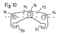
- Figure 10 is a schematic view of a further hitch having inwardly facing jaws 90 and 91 on outer and inner links 92, 93 respectively, for embracing implement pins from the outside thereof.
- the pivot 94 of the links is over-centre both with regard to the implement pins and to attachment points 95 and 96 of the dipper and tipping link. Additional locking means as described above may also be provided if necessary.
Abstract
Description
- The present invention relates to a quick-release hitch for attachment to the arm of an excavator. The hitch allows implements to be changed automatically by the driver of the excavator without the driver having to leave his control cab. Australian Patent specification No. 18602/83 describes a quick release hydraulic hitch which fits between the arm of a conventional excavator and a conventional implement, so that no modification of either the excavator or the implement is required. A number of embodiments are described and in each case the implement is attached to the hitch by means of a hydraulic mechanism. The hydraulic mechanism is required to be pressurised in order safely to retain the implement.
- A potential disadvantage of this known system is that accidental leakage of fluid from the hydraulic mechanism can cause the implement to become detached, with dangerous consequences. US-A-4,116,346, on which the preamble of
claim 1 is based, discloses a quick release hitch for attachment to an earthmoving vehicle, for picking up and retaining an implement such as a bucket, the hitch comprising a first longitudinally extending link attached to a tipping link of the vehicle, and having a transverse pin for engagement in first hooks provided on the bucket, a second longitudinally extending link attached to a lifting or dipper arm of the vehicle, having a transverse pin for engagement in second hooks provided on the bucket, the first and second links being pivotally connected together end to end to allow jack-knifing of the links, and means, in the form of an over-dead-centre spring-energised arrangement acting on the links for maintaining the pins on the links in engagement with the respective hooks on the bucket. - Quick-change hitches are also known, for example from DE-OS-273492, which have a unitary member provided with respective spaced-apart jaws to receive corresponding spaced-apart pins on an implement such as a bucket, the unitary member being pivotally connected at one end to a dipper arm of the vehicle and at the other end to a tipper arm of the vehicle, the arrangement being such that one jaw can be engaged with one pin on the implement and the unitary member then pivoted relative to the implement, about said one pin, until the other pin enters the other jaw, with a catch member being provided, mounted on the unitary member and operable to lock said other pin in said other jaw.
- It is an object of the invention to provide an improved quick release hitch in which the hitch parts can be reliably locked in positions in which the retaining formations of the hitch are in firm engagement with the complementary retaining formations of the implement over a range of spacings of such complementary retaining formations.
- In the present specification, the term "excavator" will be understood to have a wide meaning covering all machines, hydraulic or otherwise, having an implement mounted at the end of an arm, and therefore includes not only hydraulic excavators as such but also backhoes.
- A wide variety of implements may be used with the hydraulic excavator, for example the implement might be a bucket, auger, drill, tamper, a ripping-tooth, a hydraulic drill, a grader blade, or any of the other commercially available implements. Each implement will be provided with pin holes to enable it to be attached to the dipper and to the tipping links of the excavator. Such implements are conventionally provided with a pair of pins extending through the pin holes and a hitch embodying the present invention may, in such a case, be designed to co-operate with these pins, without requiring any permanent modifications.
- According to the present invention there is provided a quick release hitch for attachment to the arm of an excavator having a dipper and a tipping link, the hitch being adapted to pick up and retain an implement provided with spaced attachment formations, which hitch comprises a first longitudinally extending link having a first attachment point for attachment to the tipping link of such excavator arm, a second longitudinally extending link having a second attachment point for attachment to the dipper of such excavator arm, said first and second links being pivotally connected together end to end to allow jack-knifing thereof, and each link carrying a respective attachment formation for complementary engagement with a respective said attachment formation of such implement, and means being provided for maintaining said links in positions in which attachment formations carried by said links are in engagement with such attachment formations on such an implement when such implement has been engaged by the hitch, characterised in that said attachment formations carried by said links are jaws at the free ends of said links, for engagement with respective pins of a pair of parallel transversely extending spaced pins constituting said attachment formations on said implement, and in that said means for maintaining said links positions in which said jaws are in engagement with such pins comprises mechanical locking means mounted on one of said first and second links and operative on the other of said links to prevent relative pivotal movement of said links such as to allow separation of such pins of such implement from said jaws, said locking means comprising a rotatable cam element mounted on one link, which engages a ramp surface provided on the other link, to prevent angular movement of said one link, relative to said other link, past a limiting abutment position at which the cam element engages said ramp surface and which limiting abutment position is determined by the rotational position of said rotatable cam element, whereby the limiting abutment position of said one link, relative to the other link, can be varied over a range of positions by varying the rotational positions of said cam element.
- Alternatively or additionally, the locking means may comprise an over-centre locking mechanism. The term "over-centre mechanism" will be understood to mean a mechanism wherein the pivotal connection of the links in the engaged position is over-centre, either with respect to a line joining attachment points (of the attachement means) where the dipper and tipping link are attached to the hitch (giving partial locking); or also over-centre with respect to the jaws of the hitch (giving complete locking).
- In a simple embodiment, the links are thrown over centre by gravity due to the weight of the locking mechanism, or by manipulation of the excavator arm, to capture the implement.
- However, a drive means may be provided for pivoting the links. The drive means may be a hydraulic motor, hydraulic ram or an equivalent electrically or mechanically operated mechanism. Usually, the drive means is arranged at least to disengage the hitch by jack-knifing the links. This reduces the distance between the jaws and disengages the hitch from the implement pins.
- Means may also be provided for sliding the links longitudinally relatively to one another, so as to allow for slight variations in pin spacing. This may be done using an eccentric shaft running freely through one link and journalled into the second link. The shaft is operated by a motor secured to said one link.
- The jaws of the hitch may face towards or away from each other for engaging the implement pins from the outside or inside, respectively.
- Embodiments of the present invention will now be described, by way of example only, with reference to the drawings, wherein:
- FIGURE 1 is a side elevation of the end of an excavator arm carrying a quick release hitch for an implement.
- FIGURE 2 shows the hitch of Figure 1 being unlocked from an implement:
- FIGURES 3 and 4 are partial cross-sectional views from above showing an over-centre locking mechanism in the locked and unlocked positions respectively;
- FIGURES 5 and 6 are side elevations of the embodiments of Figures 3 and 4;
- FIGURE 7 shows a hydraulic control circuit for use with the hitch;
- FIGURE 8 is aside elevation of a hitch embodying the invention;
- FIGURE 9 is a longitudinal cross-sectional view of one of the links of the hitch of Figure 8;
- FIGURE 10 is a schematic elevation of a further hitch embodying the invention wherein the jaws are arranged to engage the implement pins from the outside.
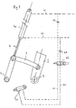
- Referring to Figures 1 and 2, a
hitch 5 is attached to an excavator arm comprising adipper 1, a tippinglink 2 and a pair ofcrowd links 3 in conventional manner. A hydraulic cylinder (not shown) acts on arod 4 for tipping the implement towards the position shown in Figure 2. - Figures 8 and 9 show a hitch embodying the invention, without the associated parts of the excavator arm. This hitch comprises an
inner link 50 and outer link 51 pivotally connected by apivot 52. The links haverespective attachment points respective jaws - As shown more clearly in Figure 9 the outer link 51 comprises a pair of spaced
upper flanges 57 and a pair of spacedlower flanges 58 interconnected by aplate 59 and abar 60. Thejaw 56 consists of a part cylindrical channel element extending transversely of the hitch. Similarly, theinner link 50 comprises a pair of interconnected upper andlower flanges 61 and 62 respectively. - The hitch of Figures 8 and 9 includes locking means for preventing pivotal movement, such as to separate the
jaws nose 63 formed as an extension of thelower flange 58, and which overlapslower flange 62. Eachlower flange 58 has aramp surface 64 which is engaged by arotatable cam 65 mounted on each upper flange 61. The cam is rotatable by a hydraulic motor (not shown). Rotation of the cam in engagement with theramp surface 64 pivots the links and moves thejaws - The following description with reference to Figures 1 to 10 discloses various features which may be incorporated in a hitch embodying the features of the invention disclosed with reference to Figures 8 and 9. However, no rotatable cam and co-operating ramp surface are shown in Figures 1 to 6, 7 and 10. The
hitch 5 shown generally in Figures 1 and 2 (from which some details are omitted) and in more detail in Figures 3 to 6, is attached by means ofpivot pins 6, 7 to the tippinglink 2 anddipper 1, respectively, of the excavator.Numerals - The
hitch 5 comprises anouter link 10 and aninner link 11. Thelinks respective jaws implement pins beak 14 provided on theouter link 10 abuts astop 15 on inner link II. - The over-centre locking mechanism is shown in more detail in Figures 3 to 6. A
hydraulic motor 16 is bolted to theinner link 11 and carries aneccentric shaft 17 which extends freely through anaperture 18 in the inner link. Theeccentric shaft 17 is bushed into acircular bushing 19 in theouter link 10. - An
arm 20 is fixed to the end ofshaft 17 and cooperates with aprojection 21 on theouter link 10 for throwing the mechanism over-centre for disengagement. Thehitch 5 may be operated as follows. The excavator arm is brought down to the position shown in Figure 2 with the implement attached and the over-centre locking mechanism in the position shown in Figures 3 and 5. Thehydraulic motor 16 is then operated so as to rotate theshaft 17 in an anti-clockwise direction from the position shown in Figure 5. Theshaft 17 is eccentrically mounted and for rotation about the axis of rotation shown in dotted links, causes retraction of theouter link 10 longitudinally towards theinner link 11, reducing the distance between thejaws implement pins shaft 17 causes the end of the arm to abut against theprojection 21, thereby throwing the locking mechanism over-centre and causinglinks jaws pins - When the
hitch 5 has been aligned above a fresh implement,hydraulic motor 16 is reversed andshaft 17 rotated in a clockwise direction. This allows thelinks beak 14 rests against thestop 15, due to the weight of the links and the hydraulic motor. Thereafter further clockwise rotation of theshaft 17 extends theouter link 10 relative to theinner link 11, thus allowing for any variations in spacing of the implementpins - In the above described arrangement, the links are moved over-centre (with respect to the pivots 6 and 7) under the effect of gravity. In another arrangement the links may be positively moved over-centre by the provision of a
further protrusion 22 shown in dotted lines in Figure 6. In this case thebushing 19 is elongated as shown in dotted lines. For engagement of the hitch, theeccentric shaft 17 is rotated clockwise until thearm 20strikes protrusion 22, which throws the mechanism over-centre. On further rotation, theelongated bush 19 allows thearm 20 to ride over thepin 22 and to continue extension of the links unitl the implementpins arm 20 to ride over thepin 22 may also be envisaged, such as by allowing thearm 20 to slide longitudinally across the end ofshaft 17 once the mechanism has been thrown over-centre. - The eccentric mounting of
shaft 17 allows for a certain degree of longitudinal movement of thelinks motor 16 longitudinally relative to theinner link 11, for example by unbolting the motor, or by rotating the motor in an eccentric arrangement mounted on theinner link 11. - In order to operate the hitch, the
motor 16 need not rotate more than 180°. It is therefore possible to replace the motor by means of a ram acting on an arm extending transversely of theshaft 17. The hydraulic motor might also be replaced by an electric motor. - Figure 7 shows a hydraulic control circuit for use with arrangements described previously. The excavator is provided with a tipping cylinder 40 having a
ram 4, and hydraulic inlet andoutlet lines Parallel lines solenoid control valve 46.Non return valves 47, 48 are provided inlines - Figure 10 is a schematic view of a further hitch having inwardly facing
jaws inner links pivot 94 of the links is over-centre both with regard to the implement pins and to attachment points 95 and 96 of the dipper and tipping link. Additional locking means as described above may also be provided if necessary.
Claims (7)
Priority Applications (1)
| Application Number | Priority Date | Filing Date | Title |
|---|---|---|---|
| AT85304746T ATE46379T1 (en) | 1984-12-07 | 1985-07-03 | SAFETY QUICK COUPLING DEVICE. |
Applications Claiming Priority (2)
| Application Number | Priority Date | Filing Date | Title |
|---|---|---|---|
| AUPG846884 | 1984-12-07 | ||
| AU8468/84 | 1984-12-07 |
Publications (2)
| Publication Number | Publication Date |
|---|---|
| EP0184282A1 EP0184282A1 (en) | 1986-06-11 |
| EP0184282B1 true EP0184282B1 (en) | 1989-09-13 |
Family
ID=3770873
Family Applications (1)
| Application Number | Title | Priority Date | Filing Date |
|---|---|---|---|
| EP85304746A Expired EP0184282B1 (en) | 1984-12-07 | 1985-07-03 | A quick-release hitch |
Country Status (6)
| Country | Link |
|---|---|
| US (1) | US4726731A (en) |
| EP (1) | EP0184282B1 (en) |
| JP (1) | JP2589974B2 (en) |
| AT (1) | ATE46379T1 (en) |
| CA (1) | CA1273903A (en) |
| DE (1) | DE3573006D1 (en) |
Families Citing this family (31)
| Publication number | Priority date | Publication date | Assignee | Title |
|---|---|---|---|---|
| GB2177674B (en) * | 1985-07-10 | 1988-10-05 | Bamford Excavators Ltd | Mounting a working implement |
| US5176463A (en) * | 1987-07-30 | 1993-01-05 | Trw United-Carr Gmbh & Co. | Joint connection between two plastic parts |
| AT392307B (en) * | 1987-09-25 | 1991-03-11 | Winkelbauer Franz | CLUTCH DEVICE |
| GB9005074D0 (en) * | 1990-03-07 | 1990-05-02 | Aubrey Martin J | Coupling |
| GB2251592B (en) * | 1990-12-01 | 1994-06-22 | Roberts & Griffiths | Attachment means |
| JP2576798Y2 (en) * | 1992-04-24 | 1998-07-16 | 株式会社室戸鉄工所 | Excavator bucket mounting |
| US5332353A (en) * | 1993-02-16 | 1994-07-26 | Wain Roy, Inc. | Quick coupler for excavation equipment |
| US5456030A (en) * | 1993-06-21 | 1995-10-10 | Barone, Inc. | Quick coupler for heavy equipment implements |
| US5546683A (en) * | 1993-09-29 | 1996-08-20 | Clark; George J. | Bucket attachment device with remote controlled retractable pins |
| JP2756078B2 (en) * | 1993-12-16 | 1998-05-25 | 博 小野寺 | Attachment coupler |
| GB9520448D0 (en) * | 1995-10-06 | 1995-12-06 | Mccann Noel P M | Excavator hitch |
| US5727342A (en) * | 1996-04-18 | 1998-03-17 | Wain-Roy, Inc. | Hydraulic latch pin assembly for coupling a tool to a construction equipment |
| FR2776316B1 (en) * | 1998-03-18 | 2000-06-16 | Mailleux Sa | HYDRAULIC LOCKING SYSTEM OF A LOADER TOOL |
| JPH11315551A (en) | 1998-03-27 | 1999-11-16 | Nippon Pneumatic Mfg Co Ltd | Quick connection device for construction machinery |
| JPH11323998A (en) * | 1998-05-14 | 1999-11-26 | Hitachi Constr Mach Co Ltd | Construction machine arm having device for attaching and detaching simplified attachment |
| GB2330570B (en) | 1998-09-08 | 1999-09-15 | Miller Ronald Keith | Quick coupler for bucket excavators |
| GB2330569B (en) | 1998-09-08 | 1999-09-15 | Miller Ronald Keith | Coupler for bucket excavators |
| MXPA02000297A (en) * | 1999-07-12 | 2002-06-21 | Jrb Co Inc | Excavator arm assembly with integral quick coupler. |
| US6431785B1 (en) | 2000-06-05 | 2002-08-13 | Wec Co. | Direct pin quick coupler |
| US6866467B2 (en) | 2000-11-29 | 2005-03-15 | Caterpillar S.A.R.L. | Hydraulically actuated quick coupling device |
| US6773223B2 (en) * | 2002-05-17 | 2004-08-10 | New Holland North America, Inc. | Hydraulic attachment latch mechanism for skid steer loader |
| US6996926B2 (en) | 2002-06-24 | 2006-02-14 | Jrb Attachments, Llc | Arm assembly for excavation apparatus and method of using same |
| US20040245002A1 (en) * | 2003-06-06 | 2004-12-09 | Shingo Muroto | Screw-rod locking structure for attachment fixture |
| IES20040194A2 (en) * | 2003-09-18 | 2005-03-23 | Caroline Mccormick | An excavator tool quick attachment device |
| JP4247211B2 (en) * | 2005-07-05 | 2009-04-02 | ヤンマー株式会社 | Locking mechanism of excavator in tractor, loader and backhoe |
| US20070201973A1 (en) * | 2006-02-28 | 2007-08-30 | Woods Equipment Company | Quick coupler system |
| DE102009012050A1 (en) * | 2009-03-06 | 2010-09-09 | Lst Gmbh | attachment |
| GB2509303A (en) | 2012-11-08 | 2014-07-02 | Miller Int Ltd | Coupler |
| US9610815B2 (en) | 2015-06-17 | 2017-04-04 | Donald Wendland | Receivers for a heavy duty locking and pushing assemblies |
| JP6430671B1 (en) * | 2018-03-15 | 2018-11-28 | 丸山 俊 | Construction machine attachment mounting jig and construction machine |
| WO2020044570A1 (en) * | 2018-08-28 | 2020-03-05 | ウエダ産業株式会社 | Attachment coupler |
Family Cites Families (33)
| Publication number | Priority date | Publication date | Assignee | Title |
|---|---|---|---|---|
| US2142454A (en) * | 1937-10-05 | 1939-01-03 | Frank C Kirkpatrick | Spring latch for cultivators |
| US2497319A (en) * | 1946-04-20 | 1950-02-14 | Int Harvester Co | Automatic release-and-catch coupling device |
| US3204793A (en) * | 1963-06-28 | 1965-09-07 | Guy E Lane | Front end loader automatic implement attachment apparatus |
| NO106518L (en) * | 1964-03-14 | 1900-01-01 | ||
| US3705656A (en) * | 1971-02-18 | 1972-12-12 | Deere & Co | Quick-attach loader bucket |
| US3935953A (en) * | 1974-06-24 | 1976-02-03 | Caterpillar Tractor Co. | Implement mounting means for earthworking vehicles |
| US4067467A (en) * | 1975-04-14 | 1978-01-10 | International Harvester Company | Quick coupler device |
| US3985249A (en) * | 1975-04-14 | 1976-10-12 | International Harvester Company | Quick change attachment |
| US4013182A (en) * | 1975-04-21 | 1977-03-22 | Rockland, Inc. | Detachable coupling system |
| JPS5294601A (en) * | 1976-02-03 | 1977-08-09 | Caterpillar Mitsubishi Ltd | Quick coupler |
| JPS52101801A (en) * | 1976-02-24 | 1977-08-26 | Caterpillar Mitsubishi Ltd | Quick coupler |
| US4068959A (en) * | 1976-11-26 | 1978-01-17 | Pemberton Bruce W | Coupler apparatus |
| SU618501A1 (en) * | 1976-12-15 | 1978-08-05 | Всесоюзный научно-исследовательский институт строительного и дорожного машиностроения | Device for securing working member of hydraulic excavator |
| US4132290A (en) * | 1977-01-13 | 1979-01-02 | Caterpillar Tractor Co. | Locking mechanism for movable vehicle members |
| DE2702728A1 (en) * | 1977-01-24 | 1978-07-27 | Agergards Maskiner Ab | COUPLING ON AN EQUIPMENT CARRIER, IN PARTICULAR FOR WORK MACHINES |
| SU616375A1 (en) * | 1977-02-14 | 1978-06-09 | Всесоюзный научно-исследовательский институт строительного и дорожного машиностроения | Excavator bucket gathering device |
| US4119225A (en) * | 1977-04-18 | 1978-10-10 | Owatonna Manufacturing Company, Inc. | Mounting means for attaching an implement to a vehicle |
| DE2734972C2 (en) * | 1977-08-03 | 1982-06-09 | O & K Orenstein & Koppel Ag, 1000 Berlin | Device for connecting serial interchangeable attachment tools |
| US4187050A (en) * | 1978-02-15 | 1980-02-05 | Caterpillar Tractor Co. | Quick-disconnect mechanical coupling |
| GB1602951A (en) * | 1978-05-31 | 1981-11-18 | Spence Eng Ltd | Couplings |
| US4345872A (en) * | 1978-07-10 | 1982-08-24 | Wain-Roy, Inc. | Connectors |
| US4239225A (en) * | 1978-12-18 | 1980-12-16 | Bally Manufacturing Corporation | Rotatable disc stop apparatus |
| US4214840A (en) * | 1979-01-18 | 1980-07-29 | J. H. Beales Steel Fabricators, Ltd. | Quick-release coupler |
| US4253793A (en) * | 1979-06-11 | 1981-03-03 | Braml Michael T | Quick attachment for loader implements |
| JPS5614818A (en) * | 1979-07-17 | 1981-02-13 | Matsushita Seiko Co Ltd | Silencer |
| US4243342A (en) * | 1979-07-27 | 1981-01-06 | J. I. Case Company | Snap fast fastener |
| US4355945A (en) * | 1979-12-03 | 1982-10-26 | Ware Machine Service, Inc. | Tool mounting apparatus |
| US4297074A (en) * | 1980-01-07 | 1981-10-27 | Ballinger Paul V | Demountable interconnection |
| US4295287A (en) * | 1980-04-10 | 1981-10-20 | J. I. Case Company | Backhoe bucket quick coupler |
| SE8003255L (en) * | 1980-04-29 | 1981-10-30 | Jan Kenneth Ragnar Gren | QUICK CONNECTION |
| AU544156B2 (en) * | 1980-11-17 | 1985-05-16 | Eimco (Great Britain) Ltd. | A coupling system for earth-moving equipment |
| NZ199611A (en) * | 1981-02-05 | 1984-09-28 | Maroochy Shire Council | Quick release and attachment assembly for construction equipment tools |
| US4436477A (en) * | 1982-03-25 | 1984-03-13 | Farmhand, Inc. | Quick attachment carrier assembly |
-
1985
- 1985-06-27 US US06/749,944 patent/US4726731A/en not_active Expired - Lifetime
- 1985-06-28 JP JP60140645A patent/JP2589974B2/en not_active Expired - Lifetime
- 1985-06-28 CA CA000486046A patent/CA1273903A/en not_active Expired - Lifetime
- 1985-07-03 AT AT85304746T patent/ATE46379T1/en active
- 1985-07-03 DE DE8585304746T patent/DE3573006D1/en not_active Expired
- 1985-07-03 EP EP85304746A patent/EP0184282B1/en not_active Expired
Also Published As
| Publication number | Publication date |
|---|---|
| EP0184282A1 (en) | 1986-06-11 |
| JP2589974B2 (en) | 1997-03-12 |
| ATE46379T1 (en) | 1989-09-15 |
| CA1273903A (en) | 1990-09-11 |
| US4726731A (en) | 1988-02-23 |
| DE3573006D1 (en) | 1989-10-19 |
| JPS61137927A (en) | 1986-06-25 |
Similar Documents
| Publication | Publication Date | Title |
|---|---|---|
| EP0184282B1 (en) | A quick-release hitch | |
| US6481124B1 (en) | Quick coupler for bucket excavators | |
| EP0405813B1 (en) | Implement attachment coupler | |
| US4660654A (en) | Implement wing frame folding apparatus with automatically pivoted biased latch | |
| DE60106865T2 (en) | UNIVERSAL CLUTCH FOR BAGGERSCHAUFEL | |
| US8585345B2 (en) | Coupler with pivoting front hook lock | |
| US7493712B2 (en) | Excavator tool quick attachment device | |
| US4295287A (en) | Backhoe bucket quick coupler | |
| EP2167738B1 (en) | Quick coupler assembly for connecting an implement to an arm of a machine | |
| US4253793A (en) | Quick attachment for loader implements | |
| US6132131A (en) | Attachment mounting/demounting device in working machinery | |
| EP0447119B1 (en) | Earth-working machine | |
| US20040165979A1 (en) | Coupler with improved pin lock | |
| US20030175072A1 (en) | Hydraulic coupler | |
| CA1248154A (en) | Trailer hitch | |
| WO1988001322A1 (en) | Improved hitch | |
| JP2674712B2 (en) | Crane type machine with articulated connection structure | |
| WO2000014343A1 (en) | Coupler for bucket excavators | |
| CA1138828A (en) | Demountable interconnection | |
| EP0578447A1 (en) | Implement attachment coupler | |
| US7866935B1 (en) | Manually operated coupler | |
| US4225283A (en) | Backhoe bucket quick coupling | |
| JPH08509531A (en) | Excavator or loader instrument coupling | |
| GB2065441A (en) | Tractor coupling hook | |
| WO1995033895A1 (en) | A quick-release hitch |
Legal Events
| Date | Code | Title | Description |
|---|---|---|---|
| PUAI | Public reference made under article 153(3) epc to a published international application that has entered the european phase |
Free format text: ORIGINAL CODE: 0009012 |
|
| AK | Designated contracting states |
Kind code of ref document: A1 Designated state(s): AT BE CH DE FR GB IT LI LU NL SE |
|
| 17P | Request for examination filed |
Effective date: 19861209 |
|
| 17Q | First examination report despatched |
Effective date: 19871201 |
|
| GRAA | (expected) grant |
Free format text: ORIGINAL CODE: 0009210 |
|
| AK | Designated contracting states |
Kind code of ref document: B1 Designated state(s): AT BE CH DE FR GB IT LI LU NL SE |
|
| PG25 | Lapsed in a contracting state [announced via postgrant information from national office to epo] |
Ref country code: SE Effective date: 19890913 Ref country code: NL Effective date: 19890913 Ref country code: LI Effective date: 19890913 Ref country code: IT Free format text: LAPSE BECAUSE OF FAILURE TO SUBMIT A TRANSLATION OF THE DESCRIPTION OR TO PAY THE FEE WITHIN THE PRESCRIBED TIME-LIMIT;WARNING: LAPSES OF ITALIAN PATENTS WITH EFFECTIVE DATE BEFORE 2007 MAY HAVE OCCURRED AT ANY TIME BEFORE 2007. THE CORRECT EFFECTIVE DATE MAY BE DIFFERENT FROM THE ONE RECORDED. Effective date: 19890913 Ref country code: FR Free format text: THE PATENT HAS BEEN ANNULLED BY A DECISION OF A NATIONAL AUTHORITY Effective date: 19890913 Ref country code: CH Effective date: 19890913 Ref country code: BE Effective date: 19890913 Ref country code: AT Effective date: 19890913 |
|
| REF | Corresponds to: |
Ref document number: 46379 Country of ref document: AT Date of ref document: 19890915 Kind code of ref document: T |
|
| REF | Corresponds to: |
Ref document number: 3573006 Country of ref document: DE Date of ref document: 19891019 |
|
| REG | Reference to a national code |
Ref country code: CH Ref legal event code: PL |
|
| EN | Fr: translation not filed | ||
| NLV1 | Nl: lapsed or annulled due to failure to fulfill the requirements of art. 29p and 29m of the patents act | ||
| PLBE | No opposition filed within time limit |
Free format text: ORIGINAL CODE: 0009261 |
|
| STAA | Information on the status of an ep patent application or granted ep patent |
Free format text: STATUS: NO OPPOSITION FILED WITHIN TIME LIMIT |
|
| PG25 | Lapsed in a contracting state [announced via postgrant information from national office to epo] |
Ref country code: LU Free format text: LAPSE BECAUSE OF NON-PAYMENT OF DUE FEES Effective date: 19900731 |
|
| 26N | No opposition filed | ||
| PGFP | Annual fee paid to national office [announced via postgrant information from national office to epo] |
Ref country code: GB Payment date: 19930622 Year of fee payment: 9 |
|
| PGFP | Annual fee paid to national office [announced via postgrant information from national office to epo] |
Ref country code: DE Payment date: 19930719 Year of fee payment: 9 |
|
| PG25 | Lapsed in a contracting state [announced via postgrant information from national office to epo] |
Ref country code: GB Effective date: 19940703 |
|
| GBPC | Gb: european patent ceased through non-payment of renewal fee |
Effective date: 19940703 |
|
| PG25 | Lapsed in a contracting state [announced via postgrant information from national office to epo] |
Ref country code: DE Effective date: 19950401 |
|
| REG | Reference to a national code |
Ref country code: SE Ref legal event code: EUG |