EP0184130B1 - Drum type image scanning and recording apparatus - Google Patents
Drum type image scanning and recording apparatus Download PDFInfo
- Publication number
- EP0184130B1 EP0184130B1 EP85115049A EP85115049A EP0184130B1 EP 0184130 B1 EP0184130 B1 EP 0184130B1 EP 85115049 A EP85115049 A EP 85115049A EP 85115049 A EP85115049 A EP 85115049A EP 0184130 B1 EP0184130 B1 EP 0184130B1
- Authority
- EP
- European Patent Office
- Prior art keywords
- drum
- string
- film
- type image
- recording apparatus
- Prior art date
- Legal status (The legal status is an assumption and is not a legal conclusion. Google has not performed a legal analysis and makes no representation as to the accuracy of the status listed.)
- Expired
Links
- 238000001514 detection method Methods 0.000 claims description 9
- 230000007246 mechanism Effects 0.000 claims description 8
- 238000000926 separation method Methods 0.000 claims description 5
- 239000000126 substance Substances 0.000 claims description 5
- 230000004044 response Effects 0.000 claims description 2
- 238000000034 method Methods 0.000 description 8
- 230000005856 abnormality Effects 0.000 description 7
- 230000008569 process Effects 0.000 description 5
- 238000010276 construction Methods 0.000 description 4
- 239000000463 material Substances 0.000 description 3
- 239000002390 adhesive tape Substances 0.000 description 2
- 230000003287 optical effect Effects 0.000 description 2
- 239000000853 adhesive Substances 0.000 description 1
- 230000001070 adhesive effect Effects 0.000 description 1
- 238000006073 displacement reaction Methods 0.000 description 1
- 230000000694 effects Effects 0.000 description 1
- 230000004907 flux Effects 0.000 description 1
- 238000013021 overheating Methods 0.000 description 1
- 230000000149 penetrating effect Effects 0.000 description 1
- 230000001737 promoting effect Effects 0.000 description 1
- 230000009467 reduction Effects 0.000 description 1
- GGCZERPQGJTIQP-UHFFFAOYSA-N sodium;9,10-dioxoanthracene-2-sulfonic acid Chemical compound [Na+].C1=CC=C2C(=O)C3=CC(S(=O)(=O)O)=CC=C3C(=O)C2=C1 GGCZERPQGJTIQP-UHFFFAOYSA-N 0.000 description 1
Images

Classifications
-
- H—ELECTRICITY
- H04—ELECTRIC COMMUNICATION TECHNIQUE
- H04N—PICTORIAL COMMUNICATION, e.g. TELEVISION
- H04N1/00—Scanning, transmission or reproduction of documents or the like, e.g. facsimile transmission; Details thereof
- H04N1/04—Scanning arrangements, i.e. arrangements for the displacement of active reading or reproducing elements relative to the original or reproducing medium, or vice versa
- H04N1/06—Scanning arrangements, i.e. arrangements for the displacement of active reading or reproducing elements relative to the original or reproducing medium, or vice versa using cylindrical picture-bearing surfaces, i.e. scanning a main-scanning line substantially perpendicular to the axis and lying in a curved cylindrical surface
- H04N1/08—Mechanisms for mounting or holding the sheet around the drum
- H04N1/083—Holding means
- H04N1/0856—Suction or vacuum means
-
- B—PERFORMING OPERATIONS; TRANSPORTING
- B65—CONVEYING; PACKING; STORING; HANDLING THIN OR FILAMENTARY MATERIAL
- B65H—HANDLING THIN OR FILAMENTARY MATERIAL, e.g. SHEETS, WEBS, CABLES
- B65H7/00—Controlling article feeding, separating, pile-advancing, or associated apparatus, to take account of incorrect feeding, absence of articles, or presence of faulty articles
- B65H7/02—Controlling article feeding, separating, pile-advancing, or associated apparatus, to take account of incorrect feeding, absence of articles, or presence of faulty articles by feelers or detectors
-
- H—ELECTRICITY
- H04—ELECTRIC COMMUNICATION TECHNIQUE
- H04N—PICTORIAL COMMUNICATION, e.g. TELEVISION
- H04N1/00—Scanning, transmission or reproduction of documents or the like, e.g. facsimile transmission; Details thereof
- H04N1/04—Scanning arrangements, i.e. arrangements for the displacement of active reading or reproducing elements relative to the original or reproducing medium, or vice versa
- H04N1/06—Scanning arrangements, i.e. arrangements for the displacement of active reading or reproducing elements relative to the original or reproducing medium, or vice versa using cylindrical picture-bearing surfaces, i.e. scanning a main-scanning line substantially perpendicular to the axis and lying in a curved cylindrical surface
-
- H—ELECTRICITY
- H04—ELECTRIC COMMUNICATION TECHNIQUE
- H04N—PICTORIAL COMMUNICATION, e.g. TELEVISION
- H04N1/00—Scanning, transmission or reproduction of documents or the like, e.g. facsimile transmission; Details thereof
- H04N1/04—Scanning arrangements, i.e. arrangements for the displacement of active reading or reproducing elements relative to the original or reproducing medium, or vice versa
- H04N1/06—Scanning arrangements, i.e. arrangements for the displacement of active reading or reproducing elements relative to the original or reproducing medium, or vice versa using cylindrical picture-bearing surfaces, i.e. scanning a main-scanning line substantially perpendicular to the axis and lying in a curved cylindrical surface
- H04N1/08—Mechanisms for mounting or holding the sheet around the drum
-
- H—ELECTRICITY
- H04—ELECTRIC COMMUNICATION TECHNIQUE
- H04N—PICTORIAL COMMUNICATION, e.g. TELEVISION
- H04N1/00—Scanning, transmission or reproduction of documents or the like, e.g. facsimile transmission; Details thereof
- H04N1/04—Scanning arrangements, i.e. arrangements for the displacement of active reading or reproducing elements relative to the original or reproducing medium, or vice versa
- H04N1/06—Scanning arrangements, i.e. arrangements for the displacement of active reading or reproducing elements relative to the original or reproducing medium, or vice versa using cylindrical picture-bearing surfaces, i.e. scanning a main-scanning line substantially perpendicular to the axis and lying in a curved cylindrical surface
- H04N1/08—Mechanisms for mounting or holding the sheet around the drum
- H04N1/0891—Detecting failure of the holding, e.g. by detecting a loose sheet
Definitions
- This invention relates to a drum type image scanning and recording apparatus and, more particularly, to an apparatus for protecting a photosensitive material such as a photosensitive film (or an original picture) wrapped on a recording drum (or a scanning drum) and attached to the drum by vacuum to prevent separation of the material from the surface of the drum as the drum rotates.
- a photosensitive material such as a photosensitive film (or an original picture) wrapped on a recording drum (or a scanning drum) and attached to the drum by vacuum to prevent separation of the material from the surface of the drum as the drum rotates.
- an image scanning and recording apparatus of a cylindrically scanning type particularly in such apparatus used for graphic arts or the like, the following steps are taken for attaching a photosensitive material such as a film, a photographic paper or the like (referred to as "film” hereinafter) to a drum in a recording unit, or for attaching an original picture to a drum in a scanning unit: perforating several holes in a line near the leading edge of the film; fitting said holes to pins (preferably the same number as the holes) aligned on the external surface of the drum and in parallel with the drum axis; tensionally wrapping the film on the drum by pulling a free or unpinned edge of the film; attaching securely the ending edge of the film to the drum using an adhesive tape or a press bar; and, at the same time, vacuum suctioning the film by way of small holes penetrating from the surface to the interior of the drum, thus positively attaching the film to the external surface of the drum as disclosed in DE-A-3313 403.
- the film can be tensionally attached securely to the recording drum solely by vacuum suctioning through small holes perforated on the external surface of the recording drum.
- a drum-type image scanning and recording apparatus as disclosed in Japanese Patent Application No. SHO 58-155664, in which: a film is kept from separating away from a rotating recording drum even in an emergency such as a power failure, vacuum apparatus failure, or the like by providing that in such an emergency, the film is kept suctioned (by vacuum) to the drum external surface for a long time.
- optical detecting means for detecting floating of the film in a noncontacting way in which a light-beam is projected nearby and along the recording drum external surface, in parallel with the axis of the drum, said light beam being interrupted when the floating of the film occurs.
- optical detection means requires complex and expensive apparatus, including the use of a laser oscillator as a light source.
- a string (25) is tensionally stretched at a slight distance from the external surface of the drum (1), in parallel with its axis of rotation, so that when a part of the film floats away from the surface of the drum and the drum is rotating, such a floating part of the film and the string come into contact with each other and the string swings.
- the swing is then detected by a swing detecting means (29, 30) and an abnormality detection signal sent out of said detecting means is inputted to the drum driving apparatus, thereby making a brake (16) mechanism stop the rotation of the recording drum immediately. At that instant, the centrifugal force impressed to the film goes down suddenly, so that the film remains attached to the drum external surface.
- the string When the floating part of the film comes in contact with the string, the string being light and mobile only swings as if it is flipped and never hooks or scatters the film. Also, the string swings in response to just modest contact with the separated film.
- the apparatus of this invention can securely detect it so as to stop the rotation of the drum, and prevent the film from scattering and injuring the surface of the drum, recording head, or scanning head and thus leading to its own loss.
- Figure 1 is a perspective view showing the fundamental construction of a typical recording unit of a drum type image scanning and recording apparatus illustrating an embodiment of this invention
- Figure 2 is a side elevational view, partly in cross section, showing typical fundamental construction of apparatus illustrating another embodiment of this invention.
- a typical recording head which projects a light flux on a film for exposing it while travelling reciprocatively along the film surface and in parallel with the recording drum axis direction is omitted in these drawings.
- illustration of a vacuum suctioning means is omitted.
- a film 2 is tensionally attached to the external surface of a recording drum 1.
- the drum 1 is driven at a high rotational speed by a drum-driving apparatus 3 which is coupled with it via hollow main shaft 5.
- a connecting channel 6 leading to a cavity 4 of the recording drum 1 along the axis.
- Connecting channel 6 is fluidly connected to one end of a vacuum suction channel 8 by way of a seal, e.g., a labyrinth seal 7.
- a vacuum apparatus 9 This vacuum apparatus, e.g., an exhausting blower, keeps the cavity 4 of drum 1 depressurized by way of the vacuum suction channel-8 and the connecting channel 6.
- check valve 10 at an appropriate position in the connecting channel 6.
- the check valve 10 blocks off the connection between the cavity 4 of the recording drum 1 and the atmosphere by closing up. This enables the cavity 4 to maintain its already established depressurized state and separation of the film 2 from the recording drum 1 is prevented. Further, it is necessary to place the check valve 10 adjacent the recording drum 1 as seen from the labyrinth 7 so as to prevent vacuum breakage through the labyrinth 7.
- an electric motor 12 is coupled to the main shaft 5 by way of a motor shaft pulley 13, a timing belt 14 and a main shaft pulley 15, and rotates the recording drum 1.
- a power brake 16 is also coupled to the main shaft 5 by way of a brake shaft pulley 17, a timing belt 18 and a main shaft pulley 19.
- a battery 20 is provided to power the apparatus in the event of a power failure.
- a disk brake 21 is provided as an additional brake mechanism. The reason for providing two brake systems is to perform the braking securely and quickly. However, either brake should suffice.
- a pressure sensor 22 detects the abnormality of the pneumatic pressure inside the vacuum suction channel 8 and provides an abnormality detection signal to the brake mechanisms 16 and 17 to effect braking, thereby quickly stopping the rotation of the recording drum 1.
- a temperature sensor 23 is also provided, to prevent overheating problems in the event that the fuse for the blower does not function normally. Bearings 24 are provided as shown in Figure 2.
- the string stretching means as shown in Figure 2, it is also suitable to connect both ends of the string 25 to tension springs 28 for subjecting the string 25 to an approximately constant tension. Other methods can also be considered. In any case, it is necessary for the string 25 to be able to experience a detectable displacement while receiving quite a light force when part of the film 2 comes in contact with it.
- film 2 suddenly becomes subjected to less centrifugal force and is enabled to remain attached to the external surface of the recording drum 1. Further, if the above abnormality detection signal is used for generating an error indication, e.g., a sound or flashing light, it is helpful to the operator.
- an error indication e.g., a sound or flashing light
- actuators 32 whose operation levers 33 are made to contact with part of the string 25 can also be utilized as shown in Figure 3. Either of such a contacting type and a noncontacting type of the swing detecting means will do but the swing detecting means must be so constructed that the swing of the string 25 may not be hindered thereby.
- the swing detecting means can comprise a mechanism in which a light shielding piece attached to the string may interrupt a path of a light (when the string makes a swing) and thus detect the swing of the string.
- this swing detecting means it would be necessary to design this swing detecting means so that the light may not expose the film, e.g., by using an infrared ray as the light.
- the distance between the string 25 and the external surface of the recording drum 1 conveniently should be about 1-2 mm, e.g., in case of the recording drum of an electronic color separator for photocopying process in which a silver salt film is subjected to scanning and exposing.
- this distance should be determined in accordance with the vacuum suction force and the centrifugal force to be exerted on the film, namely, in accordance with factors such as the speed of revolution and diameter of the recording drum and the weight of the film. Accordingly, said distance is not limited to the above-mentioned values.
- the pin projection length should be appropriately shortened in order that the pins may not make contact with the string.
- the disk brake mechanism 21 is advantageous but where the speed of rotation of the drum is low it is not necessary.
Landscapes
- Engineering & Computer Science (AREA)
- Multimedia (AREA)
- Signal Processing (AREA)
- Facsimile Scanning Arrangements (AREA)
- Facsimiles In General (AREA)
Description
- This invention relates to a drum type image scanning and recording apparatus and, more particularly, to an apparatus for protecting a photosensitive material such as a photosensitive film (or an original picture) wrapped on a recording drum (or a scanning drum) and attached to the drum by vacuum to prevent separation of the material from the surface of the drum as the drum rotates.
- In an image scanning and recording apparatus of a cylindrically scanning type, particularly in such apparatus used for graphic arts or the like, the following steps are taken for attaching a photosensitive material such as a film, a photographic paper or the like (referred to as "film" hereinafter) to a drum in a recording unit, or for attaching an original picture to a drum in a scanning unit: perforating several holes in a line near the leading edge of the film; fitting said holes to pins (preferably the same number as the holes) aligned on the external surface of the drum and in parallel with the drum axis; tensionally wrapping the film on the drum by pulling a free or unpinned edge of the film; attaching securely the ending edge of the film to the drum using an adhesive tape or a press bar; and, at the same time, vacuum suctioning the film by way of small holes penetrating from the surface to the interior of the drum, thus positively attaching the film to the external surface of the drum as disclosed in DE-A-3313 403.
- However, in such a method perforating of the film is necessary, and so is the process of securely attaching the ending edge of film to the drum by means of an adhesive tape or a press bar if the process of tensionally attaching the film to the recording drum is to be automated. These processes pose serious technical obstacles in automatization. In addition, the perforated part and the taped part of the film cause a reduction in the effective area of the film; when the pins are fitted to the holes, the film becomes deformed; and, when the film is taped, the adhesive tends to stick to the surface of the recording drum, thereby contaminating film used later on the same drum. To eliminate such inconveniences, and to make the process of tensionally attaching the film to the recording drum amenable to automatization, it is desirable that the pins on the external surface of the recording drum and the method for attaching the film by taping or the like both be omitted.
- Instead, the film can be tensionally attached securely to the recording drum solely by vacuum suctioning through small holes perforated on the external surface of the recording drum.
- However, when the film is tensionally attached to the drum solely by vacuum suction force and this force is reduced or lost suddenly while the drum is rotating the film will immediately separate away from the external surface of the drum by centrifugal force because there are no other retaining means e.g., pins or tape. After such an event, even if the film is rewrapped on the drum, it is difficult to return the film to its original wrapped position and may become useless. Moreover, such an event can lead to damage to expensive components, e.g., the drum surface or a focussing lens of a recording head.
- In view of the above problem, the applicant has proposed a drum-type image scanning and recording apparatus, as disclosed in Japanese Patent Application No. SHO 58-155664, in which: a film is kept from separating away from a rotating recording drum even in an emergency such as a power failure, vacuum apparatus failure, or the like by providing that in such an emergency, the film is kept suctioned (by vacuum) to the drum external surface for a long time.
- Even without an emergency or vacuum failure, separation of the film from the drum may occur because a rolled film itself has a propensity to curl; and complete or partial clogging of the holes perforated in the recording drum external surface may cause the film to float away from the drum surface, thus producing gaps therebetween, even during the initial stage of mounting the film on the recording drum. Among such causes that may make the film float, the propensity in the film itself to curl up is significant in rolled film that has been cut off at the part immediately adjacent the reel. This propensity of the rolled film is due to a stepwise part of the film which appears at the beginning part of the film when it is rolled on the reel. It is also due to the unevenness of the surface of the reel itself, or due to the smaller inside diameter of the reel. Such problems cannot be entirely avoided when a rolled film is used. Also, even when taping is used for attaching the film to the drum, the tape may come off the drum while it is rotating.
- Accordingly, in order to prevent the film from separating away from the drum the latter has to stop rotating immediately when the film begins to lift away from the drum surface. The applicant has investigated this problem to detect the floating or lifting of the film, using several micro switches placed in the vicinity of the recording drum surface. However, floating could not thus be securely detected because the floating part of the film was easily flattened when pressed by the switches. Even when floating could be detected, the film got hooked by the detecting levers of the microswitches, thereby promoting the film separation. Subsequently, the applicant investigated an optical detecting means for detecting floating of the film in a noncontacting way in which a light-beam is projected nearby and along the recording drum external surface, in parallel with the axis of the drum, said light beam being interrupted when the floating of the film occurs. However, in order to attain adequate detection accuracy such optical detection means requires complex and expensive apparatus, including the use of a laser oscillator as a light source. A need, therefore, exists for a simple and inexpensive solution that will hold film securely to a rotating drum.
- It is an object of this invention to provide a drum type image scanning and recording apparatus of a simple structure, capable of accurately detecting floating of a film away from the drum, and able to prevent problems that arise when the film separates from a rotating drum and causes damage to other elements.
- Therefore, to accomplish this object according to this invention, a string (25) is tensionally stretched at a slight distance from the external surface of the drum (1), in parallel with its axis of rotation, so that when a part of the film floats away from the surface of the drum and the drum is rotating, such a floating part of the film and the string come into contact with each other and the string swings. The swing is then detected by a swing detecting means (29, 30) and an abnormality detection signal sent out of said detecting means is inputted to the drum driving apparatus, thereby making a brake (16) mechanism stop the rotation of the recording drum immediately. At that instant, the centrifugal force impressed to the film goes down suddenly, so that the film remains attached to the drum external surface.
- When the floating part of the film comes in contact with the string, the string being light and mobile only swings as if it is flipped and never hooks or scatters the film. Also, the string swings in response to just modest contact with the separated film.
- As described above, if the film floats away from the drum which is rotating (or if the film has already floated at the time it was first attached to the drum), the apparatus of this invention can securely detect it so as to stop the rotation of the drum, and prevent the film from scattering and injuring the surface of the drum, recording head, or scanning head and thus leading to its own loss.
- Other objects, features, and advantages of the present invention will be seen in connection with the accompanying drawings, in which:
- Figure 1 is a perspective view showing the fundamental construction of a typical recording unit of a drum type image scanning and recording apparatus illustrating an embodiment of this invention;
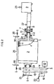
- Figure 2 is a side elevation view, partly in cross section, showing the fundamental construction of a typical recording unit of a drum type image scanning and recording apparatus illustrating another embodiment of this invention; and
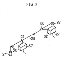
- Figure 3 is a perspective view illustrating another embodiment of a swing detecting means of this invention.
- Several embodiments of this invention are described hereunder with reference to the accompanying drawings.
- Figure 1 is a perspective view showing the fundamental construction of a typical recording unit of a drum type image scanning and recording apparatus illustrating an embodiment of this invention, and Figure 2 is a side elevational view, partly in cross section, showing typical fundamental construction of apparatus illustrating another embodiment of this invention. However, for simplicity of illustration, a typical recording head which projects a light flux on a film for exposing it while travelling reciprocatively along the film surface and in parallel with the recording drum axis direction is omitted in these drawings. Also, in Figure 1, illustration of a vacuum suctioning means is omitted.
- In these drawings, a
film 2 is tensionally attached to the external surface of a recording drum 1. The drum 1 is driven at a high rotational speed by a drum-drivingapparatus 3 which is coupled with it via hollow main shaft 5. Inside main shaft 5, there is provided a connecting channel 6 leading to a cavity 4 of the recording drum 1 along the axis. Connecting channel 6 is fluidly connected to one end of avacuum suction channel 8 by way of a seal, e.g., a labyrinth seal 7. To the other end of thevacuum suction channel 8, there is connected avacuum apparatus 9. This vacuum apparatus, e.g., an exhausting blower, keeps the cavity 4 of drum 1 depressurized by way of the vacuum suction channel-8 and the connecting channel 6. Thus suctioning (by vacuum) causes attachment offilm 2 to the external surface of the drum 1 throughsmall holes 11 which penetrate from the drum external surface to the interior cavity. - There is also provided a check valve 10 at an appropriate position in the connecting channel 6. When the capability of the
vacuum apparatus 9 goes down on account of power failure, blower failure or the like, the check valve 10 blocks off the connection between the cavity 4 of the recording drum 1 and the atmosphere by closing up. This enables the cavity 4 to maintain its already established depressurized state and separation of thefilm 2 from the recording drum 1 is prevented. Further, it is necessary to place the check valve 10 adjacent the recording drum 1 as seen from the labyrinth 7 so as to prevent vacuum breakage through the labyrinth 7. - As shown in Figure 1, an
electric motor 12 is coupled to the main shaft 5 by way of amotor shaft pulley 13, atiming belt 14 and amain shaft pulley 15, and rotates the recording drum 1. Apower brake 16 is also coupled to the main shaft 5 by way of abrake shaft pulley 17, atiming belt 18 and amain shaft pulley 19. Also, as shown in Figure 2, abattery 20 is provided to power the apparatus in the event of a power failure. Further, adisk brake 21 is provided as an additional brake mechanism. The reason for providing two brake systems is to perform the braking securely and quickly. However, either brake should suffice. - When the capability of the
vacuum apparatus 9 goes down on account of power failure, blower failure or the like, apressure sensor 22 detects the abnormality of the pneumatic pressure inside thevacuum suction channel 8 and provides an abnormality detection signal to thebrake mechanisms temperature sensor 23 is also provided, to prevent overheating problems in the event that the fuse for the blower does not function normally.Bearings 24 are provided as shown in Figure 2. - The foregoing describes a structure generally typical of conventional rotating drum type apparatus. However, in the apparatus of Figure 1, based on this invention, there is additionally provided a
string 25 which is tensionally stretched at a slight distance from the external surface of the recording drum 1 and in parallel with the direction of the axis of the drum. In the embodiment shown in Figure 1, the parts near the ends of thestring 25 are tensionally supported byguides 26, with the ends of the string connected by hangingweights 27 so that thestring 25 is always supported with an approximately constant tension. - For the string stretching means, as shown in Figure 2, it is also suitable to connect both ends of the
string 25 to tension springs 28 for subjecting thestring 25 to an approximately constant tension. Other methods can also be considered. In any case, it is necessary for thestring 25 to be able to experience a detectable displacement while receiving quite a light force when part of thefilm 2 comes in contact with it. - There are provided strongly
magnetic substances 29 adjacent both ends ofstring 25. Opposite to themagnetic substances 29 there are providedmagnetic sensors 30 which are out of contact with themagnetic substances 29. Thesemagnetic sensors 30 give abnormality detection signals in case thefilm 2 wrapped on the external surface of the recording drum 1 separates away from the drum surface. When thefilm 2 comes in contact withstring 25 it will makestring 25 swing and an abnormality signal is generated bysensors 30 when the amplitude of the swing exceeds a predetermined set value. The abnormality detection signals are amplified by an amplifier 31 and then inputted to thedrum driving apparatus 3 and thebrake mechanisms brake mechanisms motor 12 and the rotation of the recording drum 1. At that instant,film 2 suddenly becomes subjected to less centrifugal force and is enabled to remain attached to the external surface of the recording drum 1. Further, if the above abnormality detection signal is used for generating an error indication, e.g., a sound or flashing light, it is helpful to the operator. - In another embodiment, for the swing detecting means to detect the swing of the
string 25,actuators 32 whose operation levers 33 are made to contact with part of thestring 25 can also be utilized as shown in Figure 3. Either of such a contacting type and a noncontacting type of the swing detecting means will do but the swing detecting means must be so constructed that the swing of thestring 25 may not be hindered thereby. - Further, the swing detecting means can comprise a mechanism in which a light shielding piece attached to the string may interrupt a path of a light (when the string makes a swing) and thus detect the swing of the string. However, it would be necessary to design this swing detecting means so that the light may not expose the film, e.g., by using an infrared ray as the light.
- In said swing detecting means, the distance between the
string 25 and the external surface of the recording drum 1 conveniently should be about 1-2 mm, e.g., in case of the recording drum of an electronic color separator for photocopying process in which a silver salt film is subjected to scanning and exposing. However, this distance should be determined in accordance with the vacuum suction force and the centrifugal force to be exerted on the film, namely, in accordance with factors such as the speed of revolution and diameter of the recording drum and the weight of the film. Accordingly, said distance is not limited to the above-mentioned values. However, in case a film positioning means using pins aligned on the external surface of the recording drum 1 is used at the same time, the pin projection length should be appropriately shortened in order that the pins may not make contact with the string. Thedisk brake mechanism 21 is advantageous but where the speed of rotation of the drum is low it is not necessary. - The foregoing embodiments of this invention are described with regard to a recording apparatus. However, this invention can also be applicable to a scanning unit of said apparatus to which original pictures are attached to be scanned optically.
Claims (6)
the rotation of the drum (1) is stopped by a brake mechanism (21) coupled directly to the drum (1) and which operates in response to said detection signal from said swing detecting means.
said swing detecting means comprises actuators with operation levers (33) which contact a part of said string (25) when said string (25) is itself contacted by separation of said film (2) from said drum (1).
said string stretching means comprises tension spring (28) connected to at least one end of said string (25).
Applications Claiming Priority (2)
| Application Number | Priority Date | Filing Date | Title |
|---|---|---|---|
| JP59256166A JPS61133768A (en) | 1984-12-03 | 1984-12-03 | Drum type image scanning recorder |
| JP256166/84 | 1984-12-03 |
Publications (3)
| Publication Number | Publication Date |
|---|---|
| EP0184130A2 EP0184130A2 (en) | 1986-06-11 |
| EP0184130A3 EP0184130A3 (en) | 1987-05-27 |
| EP0184130B1 true EP0184130B1 (en) | 1991-01-23 |
Family
ID=17288818
Family Applications (1)
| Application Number | Title | Priority Date | Filing Date |
|---|---|---|---|
| EP85115049A Expired EP0184130B1 (en) | 1984-12-03 | 1985-11-27 | Drum type image scanning and recording apparatus |
Country Status (4)
| Country | Link |
|---|---|
| US (1) | US4637710A (en) |
| EP (1) | EP0184130B1 (en) |
| JP (1) | JPS61133768A (en) |
| DE (1) | DE3581509D1 (en) |
Cited By (1)
| Publication number | Priority date | Publication date | Assignee | Title |
|---|---|---|---|---|
| DE102005045275A1 (en) * | 2005-09-22 | 2007-03-29 | Koenig & Bauer Ag | Printing plate`s holohedral support detecting device for direct imaging printing machine, has sensor device comprising transmitter and receiver that lie outside of area above printing surface of plate, where transmitter emits measuring ray |
Families Citing this family (8)
| Publication number | Priority date | Publication date | Assignee | Title |
|---|---|---|---|---|
| JPS62116937A (en) * | 1985-11-16 | 1987-05-28 | Dainippon Screen Mfg Co Ltd | Film attaching and detaching device for drum type image scanning and recording device |
| US5019860A (en) * | 1988-07-04 | 1991-05-28 | Toyo Ink Manufacturing Co., Ltd. | Apparatus for image formation and method of image formation |
| US5291392A (en) * | 1992-02-19 | 1994-03-01 | Gerber Systems Corporation | Method and apparatus for enhancing the accuracy of scanner systems |
| GB9316355D0 (en) * | 1993-08-06 | 1993-09-22 | Itek Colour Graphics Ltd | Rotary drum scanner |
| JP2928078B2 (en) * | 1994-02-10 | 1999-07-28 | 大日本スクリーン製造株式会社 | Drilling device in cylindrical inner surface scanning device |
| JP2895735B2 (en) * | 1994-02-14 | 1999-05-24 | 大日本スクリーン製造株式会社 | Cylindrical inner surface scanning device |
| US5910651A (en) * | 1997-07-15 | 1999-06-08 | Gerber Systems Corporation | Method and apparatus for image nonlinearity compensation in scanning systems |
| JP4586751B2 (en) * | 2006-03-14 | 2010-11-24 | コニカミノルタエムジー株式会社 | Image recording device |
Family Cites Families (9)
| Publication number | Priority date | Publication date | Assignee | Title |
|---|---|---|---|---|
| CH570335A5 (en) * | 1974-06-20 | 1975-12-15 | Peyer Siegfried | |
| US4054884A (en) * | 1974-12-16 | 1977-10-18 | Exxon Research And Engineering Company | Facsimile copy medium |
| JPS5751255Y2 (en) * | 1977-03-24 | 1982-11-09 | ||
| US4111565A (en) * | 1977-03-28 | 1978-09-05 | Xerox Corporation | Apparatus for sensing when paper utilized in a printer has been depleted |
| US4330798A (en) * | 1978-04-10 | 1982-05-18 | Heyer Arthur J | Electronic stencil cutter |
| JPS564013A (en) * | 1979-06-26 | 1981-01-16 | Ricoh Co Ltd | Device for detecting failure in mounting recording paper in cylinder scanning type recording device |
| JPS5763533A (en) * | 1980-10-02 | 1982-04-17 | Konan Camera Kenkyusho:Kk | Photographic film scanner |
| CH656955A5 (en) * | 1982-05-28 | 1986-07-31 | Contraves Gmbh | METHOD AND DEVICE FOR CLAMPING, HOLDING AND CLAMPING A SHEET-SHAPED RECORDING CARRIER ON A DRUM. |
| JPS6046658A (en) * | 1983-08-24 | 1985-03-13 | Dainippon Screen Mfg Co Ltd | Drum type picture scanning and recording device |
-
1984
- 1984-12-03 JP JP59256166A patent/JPS61133768A/en active Pending
-
1985
- 1985-11-19 US US06/799,727 patent/US4637710A/en not_active Expired - Fee Related
- 1985-11-27 DE DE8585115049T patent/DE3581509D1/en not_active Expired - Lifetime
- 1985-11-27 EP EP85115049A patent/EP0184130B1/en not_active Expired
Cited By (2)
| Publication number | Priority date | Publication date | Assignee | Title |
|---|---|---|---|---|
| DE102005045275A1 (en) * | 2005-09-22 | 2007-03-29 | Koenig & Bauer Ag | Printing plate`s holohedral support detecting device for direct imaging printing machine, has sensor device comprising transmitter and receiver that lie outside of area above printing surface of plate, where transmitter emits measuring ray |
| DE102005045275B4 (en) * | 2005-09-22 | 2016-11-17 | Koenig & Bauer Ag | Method for detecting the entire surface of a flat printing plate |
Also Published As
| Publication number | Publication date |
|---|---|
| US4637710A (en) | 1987-01-20 |
| EP0184130A3 (en) | 1987-05-27 |
| DE3581509D1 (en) | 1991-02-28 |
| JPS61133768A (en) | 1986-06-21 |
| EP0184130A2 (en) | 1986-06-11 |
Similar Documents
| Publication | Publication Date | Title |
|---|---|---|
| US4637710A (en) | Drum type image scanning and recording apparatus | |
| US4770361A (en) | Web takeup apparatus | |
| US20110024020A1 (en) | Tape adhering method and tape adhering device | |
| EP1089547A2 (en) | Media feed apparatus for imaging system | |
| EP0381459A2 (en) | Sheet supplying device having control unit for sheet supplying operation | |
| JP2504539B2 (en) | Label sticking device | |
| US5110062A (en) | Detection apparatus for paper build up on reel bar | |
| US4555076A (en) | Film handling device | |
| EP0762191B1 (en) | Method for forwarding and rewinding photosensitive material | |
| JPH0430779B2 (en) | ||
| JPH0622489Y2 (en) | Coil tip position detector | |
| KR20010085342A (en) | Tape-like member transfer system | |
| JPH1111791A (en) | Detector, and web feed system | |
| JPS6111726Y2 (en) | ||
| EP0381460A3 (en) | Image forming apparatus having sheet feeding condition detecting means | |
| JPH0742014B2 (en) | Journal paper automatic winding device | |
| US5285980A (en) | Device for extracting the end of a negative film from a cartridge | |
| JPS6055369A (en) | Form wind-in preventing mechanism of fuser roll | |
| JPH03139625A (en) | Detection device | |
| EP0270105A2 (en) | Method of and apparatus for recording image | |
| JPS5895061A (en) | Recording paper end detecting method in recording apparatus | |
| KR910004726Y1 (en) | Drum protection device for vtr | |
| JPH04358652A (en) | Medium detecting device | |
| JP3108179B2 (en) | Feeding method of optical fiber | |
| CA1090866A (en) | Sheet removing device for use in electro-photographic copying machine |
Legal Events
| Date | Code | Title | Description |
|---|---|---|---|
| PUAI | Public reference made under article 153(3) epc to a published international application that has entered the european phase |
Free format text: ORIGINAL CODE: 0009012 |
|
| AK | Designated contracting states |
Kind code of ref document: A2 Designated state(s): DE FR GB |
|
| PUAL | Search report despatched |
Free format text: ORIGINAL CODE: 0009013 |
|
| AK | Designated contracting states |
Kind code of ref document: A3 Designated state(s): DE FR GB |
|
| 17P | Request for examination filed |
Effective date: 19870716 |
|
| 17Q | First examination report despatched |
Effective date: 19890821 |
|
| GRAA | (expected) grant |
Free format text: ORIGINAL CODE: 0009210 |
|
| AK | Designated contracting states |
Kind code of ref document: B1 Designated state(s): DE FR GB |
|
| ET | Fr: translation filed | ||
| REF | Corresponds to: |
Ref document number: 3581509 Country of ref document: DE Date of ref document: 19910228 |
|
| PLBE | No opposition filed within time limit |
Free format text: ORIGINAL CODE: 0009261 |
|
| STAA | Information on the status of an ep patent application or granted ep patent |
Free format text: STATUS: NO OPPOSITION FILED WITHIN TIME LIMIT |
|
| 26N | No opposition filed | ||
| PGFP | Annual fee paid to national office [announced via postgrant information from national office to epo] |
Ref country code: FR Payment date: 19941109 Year of fee payment: 10 |
|
| PGFP | Annual fee paid to national office [announced via postgrant information from national office to epo] |
Ref country code: GB Payment date: 19941117 Year of fee payment: 10 |
|
| PGFP | Annual fee paid to national office [announced via postgrant information from national office to epo] |
Ref country code: DE Payment date: 19941123 Year of fee payment: 10 |
|
| PG25 | Lapsed in a contracting state [announced via postgrant information from national office to epo] |
Ref country code: GB Effective date: 19951127 |
|
| GBPC | Gb: european patent ceased through non-payment of renewal fee |
Effective date: 19951127 |
|
| PG25 | Lapsed in a contracting state [announced via postgrant information from national office to epo] |
Ref country code: FR Effective date: 19960731 |
|
| PG25 | Lapsed in a contracting state [announced via postgrant information from national office to epo] |
Ref country code: DE Effective date: 19960801 |
|
| REG | Reference to a national code |
Ref country code: FR Ref legal event code: ST |