EP0183664A2 - Ski holding device - Google Patents
Ski holding device Download PDFInfo
- Publication number
- EP0183664A2 EP0183664A2 EP85850368A EP85850368A EP0183664A2 EP 0183664 A2 EP0183664 A2 EP 0183664A2 EP 85850368 A EP85850368 A EP 85850368A EP 85850368 A EP85850368 A EP 85850368A EP 0183664 A2 EP0183664 A2 EP 0183664A2
- Authority
- EP
- European Patent Office
- Prior art keywords
- box
- skis
- holding device
- boot
- ski holding
- Prior art date
- Legal status (The legal status is an assumption and is not a legal conclusion. Google has not performed a legal analysis and makes no representation as to the accuracy of the status listed.)
- Withdrawn
Links
Images


Classifications
-
- A—HUMAN NECESSITIES
- A63—SPORTS; GAMES; AMUSEMENTS
- A63C—SKATES; SKIS; ROLLER SKATES; DESIGN OR LAYOUT OF COURTS, RINKS OR THE LIKE
- A63C11/00—Accessories for skiing or snowboarding
- A63C11/02—Devices for stretching, clamping or pressing skis or snowboards for transportation or storage
- A63C11/023—Carrying-devices
- A63C11/025—Carrying-devices for skis or ski-sticks
-
- Y—GENERAL TAGGING OF NEW TECHNOLOGICAL DEVELOPMENTS; GENERAL TAGGING OF CROSS-SECTIONAL TECHNOLOGIES SPANNING OVER SEVERAL SECTIONS OF THE IPC; TECHNICAL SUBJECTS COVERED BY FORMER USPC CROSS-REFERENCE ART COLLECTIONS [XRACs] AND DIGESTS
- Y10—TECHNICAL SUBJECTS COVERED BY FORMER USPC
- Y10S—TECHNICAL SUBJECTS COVERED BY FORMER USPC CROSS-REFERENCE ART COLLECTIONS [XRACs] AND DIGESTS
- Y10S224/00—Package and article carriers
- Y10S224/917—Ski carrier
Definitions
- This invention relates to a ski holding device of a kind rendering it for a person easier to carry skis.
- the present invention relates to a ski holding device, which renders the carrying of skis, especially of skis for downhill running, substantially easier.
- the present invention thus, relates to a ski holding device,-which is intended to be utilized at the carrying of skis, especially of downhill running skis.
- the invention is characterized, in that the ski holding device comprises an upwardly open box, which is to be placed on the outside of a boot, and which has a horizontal cross--section, which as to its width and, respectively, length exceeds the thickness and, respectively, width of the rear ends of a pair of skis, and into which box the rear ends of a pair pf skis are intended to be slipped down and be supported by the bottom portion of the box.
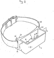
- Figs. 1 and 2 are perspective views of a ski holding device according to a first embodiment
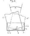
- Fig. 3 is a section along the line A-A in Fig. 2
- Fig. 4 is a perspective view of a ski holding device according to a second embodiment
- Fig. 5 is a perspective view of a ski holding device according to a third embodiment
- Fig. 6 shows a ski holding device according to the invention mounted on a ski boot.
- a ski holding device 1 according to a first embodiment of the invention is shown.
- the ski holding device 1 comprises an upwardly open box 2 to be placed on the outside of a boot 3, see Fig. 3.
- the bpx 2 has a horizontal cross-section, which as to width and, respectively, length exceeds the thickness and, respectively, width of the rear ends 6,7 of a pair of skis 4,5.
- the rear ends of a pair of skis 4,5 are intended to be slipped down into the box 2 and be supported by the bottom portion 8 of the box.
- a ridge 9 is located in the bottom portion 8 of the box 2 and extends in a direction transverse to the longitudinal direction of the box. As illustrated in Fig. 3, the rear ends 6,7 of a pair of skis 4,5 are intended to rest on said ridge. On each side of said ridge apertures 10, 11 are located, each of which has a size permitting the rear corners 12,13 of a pair of skis to be inserted into and through the aperture, as illustrated in Fig. 3.
- ridge 9 and apertures 10,11 imply, that a pair of skis 5 can be angled relative to the box where the rear ends of the pair of skis abut the ridge 9 substantially at the centre of the ends.
- the skis can be angled from the position 5 indicated by fully drawn lines to the position 5' indicated by dashed lines, which corresponds to an angle p( .
- the angle x can be varied.
- a suitable angle p can be of the magnitude 30 0 .
- the skis very easily can be moved forth and back by hand in the directions 14 indicated in Fig. 3.
- the hand and foot can be moved in a normal way when a person carries along the skis in the way illustrated in F ig. 3.
- one or several grooves 15,16 are located in that portion 17 of the box 2 which is intended to be nearest to the boot 3.
- a catching belt 18 extends, which is intended to be clamped about the leg of a boot as illustrated in Fig. 3.
- the grooves preferably extend from the outer edges 19,20 of the box, see Figs. 1 and 2, in order thereby to be able to firmly attach the box to a boot, so that the box only very restrictedly can be turned relative to the boot.
- the bottom 22 of the box 21 is plane or substantially plane.
- a plurality of apertures 23,24 are located to provide sufficient draining and to make it possible to clean the box from snow.
- This object also is achieved by the apertures 10,11 at the embodiment described above. Due to the planeness of the box bottom, however, it is desired so to design the ski holding device that the box can be turned relative to the boot through an angle of about 30°.
- this is achieved in that one 25 or several grooves for a catching belt 18 are provided, which groove or grooves are formed so that the length 26, along which the catching belt 18 is attached relative to the box 21, is substantially shorter than the entire length 27 of the box.
- the catching belt 18 hereby serves as a link. The shorter the length 26, the more the box 21 can be turned for the same temsion in the catching belt 18.
- the box 28 is rotatably connected to an attachment member 29 via a joint 30.
- the attachment member 29 together with the box 28 have about the same shape as the box 21 in Fig. 4.
- the joint 30 is a through pin attached in the attachment member 29 and, respectively, box 28.
- the attachment member is provided with one or several grooves 31 designed in a way corresponding to the grooves 15,16 shown in Fig. 1, viz. so that the attachment member can be clamped on the boot substantially non-rotary by means of the catching belt 18.
- the bottom 32 of the box is designed as a plane bottom with apertures 33,34.
- the box is a part integrated with a boot.
- an attachment member corresponding to the attachment member 29 can be formed in the leg of the boot, while the box-28 is supported by a joint 30 relative to the boot.
- a box can be formed directly in the leg of the boot.
- a box 2 of the design shown in Fig. 1 can be arranged so as to be inserted down into a dovetail groove formed in the boot leg, which groove is capable to enclose the pointed corners 35,36 and adjacent portions of the box 2.
- the inner dimensions of the box are such that the length is 8-10 cm, the width 2-3 cm, and the height 2-3 cm.
- the inner measures of the box are to be adapted to the type of skis to be carried.
- the box preferably is made of a high-quality plastic material, for example so-called ABS-plastic.
- ski holding device according to the invention can be designed in ways different from those described above without abandoning the invention idea, viz. so to arrange a ski holding device on a boot that the rear ends of a pair of skis are supported by the box.
Abstract
A ski holding device to be utilized for carrying skis, especially skis for downhill running. According to the invention, the ski holding device comprises an upwardly open box (2) to be placed on the outside of a boot, which box has a horizontal cross-section, which as to width and, respectively, length exceeds the thickness and, respectively, width of the rear ends of a pair of skis, in which box the rear ends of a pair of skis are intended to be slipped down and supported by the bottom portion (8) of the box (2).
Description
- This invention relates to a ski holding device of a kind rendering it for a person easier to carry skis.
- Skis of all sorts of types, but especially skis for downhill running, are relatively heavy and unwieldy to carry. Normally such skis are carried in such a way, that two skis are laid together and carried on one shoulder. Skis, however, are of angular shape and hard. As, besides, the ski-bindings often comprise many projecting portions and details, e.g. adjusting knobs and ski-brakes, it is generally uncomfortable to carry skis on one shoulder. The skis, moreover, easily tear holes at the shoulder in the clothes. It is, for natural reasons, for children still more difficult than for adults to carry the skis on one shoulder.
- The present invention relates to a ski holding device, which renders the carrying of skis, especially of skis for downhill running, substantially easier.
- The present invention, thus, relates to a ski holding device,-which is intended to be utilized at the carrying of skis, especially of downhill running skis. The invention is characterized, in that the ski holding device comprises an upwardly open box, which is to be placed on the outside of a boot, and which has a horizontal cross--section, which as to its width and, respectively, length exceeds the thickness and, respectively, width of the rear ends of a pair of skis, and into which box the rear ends of a pair pf skis are intended to be slipped down and be supported by the bottom portion of the box.
- The invention is described in greater detail in the following, with reference to embodiments shown in the accompanying drawings, in which Figs. 1 and 2 are perspective views of a ski holding device according to a first embodiment, Fig. 3 is a section along the line A-A in Fig. 2,
- Fig. 4 is a perspective view of a ski holding device according to a second embodiment, Fig. 5 is a perspective view of a ski holding device according to a third embodiment, Fig. 6 shows a ski holding device according to the invention mounted on a ski boot.
- In the Figs. 1,2 and 3 a
ski holding device 1 according to a first embodiment of the invention is shown. - The
ski holding device 1 comprises an upwardlyopen box 2 to be placed on the outside of aboot 3, see Fig. 3. Thebpx 2 has a horizontal cross-section, which as to width and, respectively, length exceeds the thickness and, respectively, width of the rear ends 6,7 of a pair ofskis skis box 2 and be supported by thebottom portion 8 of the box. - According to a first embodiment,a ridge 9 is located in the
bottom portion 8 of thebox 2 and extends in a direction transverse to the longitudinal direction of the box. As illustrated in Fig. 3, the rear ends 6,7 of a pair ofskis said ridge apertures rear corners 12,13 of a pair of skis to be inserted into and through the aperture, as illustrated in Fig. 3. - At an embodiment where the box is attached to a
boot 3 in such a way, that thebox 2 cannot, or to a very limited extent, be turned relative to the boot, said ridge 9 andapertures skis 5 can be angled relative to the box where the rear ends of the pair of skis abut the ridge 9 substantially at the centre of the ends. As illustrated in Fig. 3, the skis can be angled from theposition 5 indicated by fully drawn lines to the position 5' indicated by dashed lines, which corresponds to an angle p( . Depending on the height of the ridge 9 and the length of theapertures - At such an embodiment the skis very easily can be moved forth and back by hand in the
directions 14 indicated in Fig. 3. Hereby the hand and foot can be moved in a normal way when a person carries along the skis in the way illustrated in Fig. 3. - For attaching the
box 2 to aboot 3, according to one embodiment one orseveral grooves portion 17 of thebox 2 which is intended to be nearest to theboot 3. In said groove or grooves acatching belt 18 extends, which is intended to be clamped about the leg of a boot as illustrated in Fig. 3. In cases when the bottom of the box is provided with a ridge 9,,the grooves preferably extend from theouter edges - According to a second embodiment of the invention illustrated in Fig. 4, the
bottom 22 of the box 21 is plane or substantially plane. In the bottom a plurality ofapertures apertures catching belt 18 are provided, which groove or grooves are formed so that thelength 26, along which thecatching belt 18 is attached relative to the box 21, is substantially shorter than the entire length 27 of the box. Thecatching belt 18 hereby serves as a link. The shorter thelength 26, the more the box 21 can be turned for the same temsion in thecatching belt 18. - According to a third embodiment of the invention, the box 28 is rotatably connected to an
attachment member 29 via a joint 30. As appears from Fig. 5, theattachment member 29 together with the box 28 have about the same shape as the box 21 in Fig. 4. The joint 30 is a through pin attached in theattachment member 29 and, respectively, box 28. According to this embodiment, the attachment member is provided with one orseveral grooves 31 designed in a way corresponding to thegrooves catching belt 18. According to this embodiment, thebottom 32 of the box is designed as a plane bottom withapertures - According to a fourth embodiment, which is not illustrated in the accompanying Figures, the box is a part integrated with a boot. In this case, according to one embodiment an attachment member corresponding to the
attachment member 29 can be formed in the leg of the boot, while the box-28 is supported by a joint 30 relative to the boot. According to another embodiment, a box can be formed directly in the leg of the boot. At a further embodiment, abox 2 of the design shown in Fig. 1 can be arranged so as to be inserted down into a dovetail groove formed in the boot leg, which groove is capable to enclose the pointed corners 35,36 and adjacent portions of thebox 2. - The inner dimensions of the box, for example, are such that the length is 8-10 cm, the width 2-3 cm, and the height 2-3 cm. The inner measures of the box, of course, are to be adapted to the type of skis to be carried. The box preferably is made of a high-quality plastic material, for example so-called ABS-plastic.
- It is obvious that the ski holding device according to the invention can be designed in ways different from those described above without abandoning the invention idea, viz. so to arrange a ski holding device on a boot that the rear ends of a pair of skis are supported by the box.
- The present invention, thus, must not be regarded restricted to the embodiments set forth above, but can be varied within the scope defined in the attached claims.
Claims (6)
1. A ski holding device to be utilized for carrying skis, especially skis for downhill running, characterized i n that the ski holding device comprises an upwardly open box (2;21;28) to be placed on the outside of a boot, which box has a horizontal cross-section, which as to the width and, respectively, length exceeds the thickness and, respectively, width of the rear ends of a pair of skis, into which box the rear ends of a pair of skis are intended to be slipped down and supported by the bottom portion (8; 22;32) of the box (2;21;28).
2. A ski holding device as defined in claim 1, characterized i n that the box comprises one or several grooves (15,16;31;25) in that portion (17;29) which is intended to be located nearest to a boot, in which groove or grooves (15,16;31;25) a catching belt (18) extends, which is intended to be clamped about the leg of a boot.
3. A ski holding device as defined in claim 1 or 2, characterized in that a ridge (9) is located in the bottom (8) of the box (2) and extends in a direction transverse to the longitudinal direction of the box (2), on which ridge the rear ends of a pair of skis are intended to rest, and an aperture (10,11) through the bottom (8) is located on both sides of said ridge (9), which openings (10,11) each have a size permitting the rear corners of a pair of skis to be inserted down into and through the aperture.
4. A ski holding device as defined in claim 1, characterized in that the box (28) is rotatably connected to an attachment member (29) via a joint (30), which attachment member (29) is to be attached to the leg of a boot.
5. A ski holding device as defined in claim 4, characterized in that the attachment member (29) comprises one or several grooves (31), in which a catching belt (18) is intended to extend and be clamped about the leg of a boot.
6. A ski holding device as defined in claim 1, characterized in that the box (2) is a part integrated with a boot.
Applications Claiming Priority (2)
| Application Number | Priority Date | Filing Date | Title |
|---|---|---|---|
| SE8405866 | 1984-11-21 | ||
| SE8405866A SE8405866L (en) | 1984-11-21 | 1984-11-21 | SKIDHALLARE |
Publications (2)
| Publication Number | Publication Date |
|---|---|
| EP0183664A2 true EP0183664A2 (en) | 1986-06-04 |
| EP0183664A3 EP0183664A3 (en) | 1988-06-01 |
Family
ID=20357852
Family Applications (1)
| Application Number | Title | Priority Date | Filing Date |
|---|---|---|---|
| EP85850368A Withdrawn EP0183664A3 (en) | 1984-11-21 | 1985-11-15 | Ski holding device |
Country Status (3)
| Country | Link |
|---|---|
| US (1) | US4681246A (en) |
| EP (1) | EP0183664A3 (en) |
| SE (1) | SE8405866L (en) |
Families Citing this family (13)
| Publication number | Priority date | Publication date | Assignee | Title |
|---|---|---|---|---|
| US4871102A (en) * | 1988-11-09 | 1989-10-03 | Wickersham John M | Ski retaining device |
| US5941435A (en) * | 1996-03-25 | 1999-08-24 | Stephen James Smith | Collapsible, quick-release snowboarding pole with leg mounting system |
| US6217072B1 (en) | 1998-04-15 | 2001-04-17 | Jeffrey G. Gregg | Snowboard pole system |
| US6789555B1 (en) | 2002-07-25 | 2004-09-14 | Clarence Thomas | Umbrella and article holder |
| US7527182B1 (en) * | 2003-11-20 | 2009-05-05 | Get Outdoors Hunting L.L.C. | Lower leg archery bow support |
| DK176011B1 (en) * | 2004-04-14 | 2005-11-28 | Jesper Erichsen | ski Rack |
| US7658413B2 (en) * | 2004-07-02 | 2010-02-09 | Andon Malone | Retractable snow pole and snowboard binding combination |
| DE202005014506U1 (en) * | 2005-05-31 | 2006-10-12 | Wolff, Regina | Skitragevorrichtung |
| US20070209107A1 (en) * | 2006-03-09 | 2007-09-13 | Nassif Claude L | Bathing support and entertainment apparatus |
| US20090288327A1 (en) * | 2008-05-23 | 2009-11-26 | Donald John Roden | Barrel Rest |
| ES2343827B1 (en) * | 2008-09-05 | 2011-06-16 | Sabina Francisc Estrugo Mari | DEVICE FOR THE TRANSPORT OF SKIS. |
| ES2372219B8 (en) * | 2010-04-19 | 2013-04-12 | Sabina Francisca Estrugo Marí | IMPROVEMENTS INTRODUCED IN THE PATENT OF INVENTION NUM. P-200802560/8 BY: DEVICE FOR THE TRANSPORT OF SKIS. |
| GB2528475B (en) * | 2014-07-23 | 2017-02-08 | Reid Paul | Carrying ski equipment |
Citations (2)
| Publication number | Priority date | Publication date | Assignee | Title |
|---|---|---|---|---|
| US3718242A (en) * | 1970-06-04 | 1973-02-27 | R Larson | Ski carrier |
| DE8234988U1 (en) * | 1983-06-16 | Wurm, Helmut, Dipl.-Ing.(FH), 7800 Freiburg | Ski carrying device |
Family Cites Families (8)
| Publication number | Priority date | Publication date | Assignee | Title |
|---|---|---|---|---|
| US2822116A (en) * | 1955-10-24 | 1958-02-04 | Edward W Smalley | Combination bait box and carrier |
| US3232501A (en) * | 1963-11-06 | 1966-02-01 | Merenda James | Archery bow holsters |
| US3208653A (en) * | 1964-02-04 | 1965-09-28 | Robert W Wallace | Support for an archery bow |
| US3294298A (en) * | 1964-12-07 | 1966-12-27 | Richard E Danielson | Hammer holder |
| US3322311A (en) * | 1965-11-22 | 1967-05-30 | John H Homer | Article holder |
| US4103807A (en) * | 1977-03-07 | 1978-08-01 | Lyon John A | Compound bow holsters |
| US4363433A (en) * | 1978-03-31 | 1982-12-14 | Dean Jaques | Painter's holster |
| US4588116A (en) * | 1983-11-29 | 1986-05-13 | Smith & Wesson Chemical Company, Inc. | Holster for a chemical tear gas projector |
-
1984
- 1984-11-21 SE SE8405866A patent/SE8405866L/en not_active Application Discontinuation
-
1985
- 1985-11-15 EP EP85850368A patent/EP0183664A3/en not_active Withdrawn
- 1985-11-21 US US06/800,210 patent/US4681246A/en not_active Expired - Fee Related
Patent Citations (2)
| Publication number | Priority date | Publication date | Assignee | Title |
|---|---|---|---|---|
| DE8234988U1 (en) * | 1983-06-16 | Wurm, Helmut, Dipl.-Ing.(FH), 7800 Freiburg | Ski carrying device | |
| US3718242A (en) * | 1970-06-04 | 1973-02-27 | R Larson | Ski carrier |
Also Published As
| Publication number | Publication date |
|---|---|
| EP0183664A3 (en) | 1988-06-01 |
| SE8405866L (en) | 1986-05-22 |
| SE8405866D0 (en) | 1984-11-21 |
| US4681246A (en) | 1987-07-21 |
Similar Documents
| Publication | Publication Date | Title |
|---|---|---|
| EP0183664A2 (en) | Ski holding device | |
| DE69201630T2 (en) | Non-rectangular cut skis. | |
| DE69101217D1 (en) | Ski with tread part, upper body and support for bindings. | |
| DE69201341D1 (en) | Skis with a non-rectangular average. | |
| FR2648721B1 (en) | SKI COMPRISING A LAMINATED BAND INTEGRATED IN THE TOP BAND | |
| IT8322945A0 (en) | AGRICULTURAL TRACTOR WITH SEVERAL FRONT AND REAR WHEELS HAVING DISTINCT FOOTPRINTS ON THE GROUND WHILE RUNNING. | |
| US20010013157A1 (en) | Device to close footwear and clamp footwear to sports equipment | |
| IT8420676V0 (en) | FOOTWEAR CLOSED WITH SEAT FOR THE HALL ON THE TOE. | |
| FR2740982B1 (en) | SNOW SNOWBOARD | |
| EP0281051A3 (en) | Device for adjusting the flexibility in a ski boot | |
| EP0320464B1 (en) | Fitting for skiers, mountain climbers and sports uses in general | |
| EP0406179B1 (en) | Skicarrier | |
| USD395686S (en) | Hand and wrist weight | |
| USD357296S (en) | Snowboard binding | |
| FR2699373B3 (en) | Ski clothing for sports use in particular, with integrated shin guards. | |
| USD480332S1 (en) | Snowmobile ski | |
| USD377564S (en) | Shoulder pad for carrying skis | |
| FR2675390B1 (en) | WINTER SPORTS SKI COMPRISING A BASE, A STRAINER AND A SUPPORT FOR BINDINGS. | |
| Cunningham | Paradigmatic change in voluntary sport organizations | |
| EP0748246A1 (en) | Device for the individual transport of skis and ski-sticks | |
| Nighswonger | Criteria for autonomy in sport participation | |
| FR2675882B1 (en) | DEVICE FOR ADJUSTING LENGTH AND SIMULTANEOUS LOCKING OF A SUPPORT FOOT FOLLOWING TWO PERPENDICULAR ORIENTATIONS IN RELATION TO THE OTHER. | |
| DE20020868U1 (en) | Roller board | |
| Giudice | Flavor changing neutral currents in N= 1 supergravity models | |
| Yip | On Carmichael type problems for the Schemmel totients and some related questions |
Legal Events
| Date | Code | Title | Description |
|---|---|---|---|
| PUAI | Public reference made under article 153(3) epc to a published international application that has entered the european phase |
Free format text: ORIGINAL CODE: 0009012 |
|
| AK | Designated contracting states |
Kind code of ref document: A2 Designated state(s): AT CH DE FR GB IT LI |
|
| PUAL | Search report despatched |
Free format text: ORIGINAL CODE: 0009013 |
|
| AK | Designated contracting states |
Kind code of ref document: A3 Designated state(s): AT CH DE FR GB IT LI |
|
| STAA | Information on the status of an ep patent application or granted ep patent |
Free format text: STATUS: THE APPLICATION IS DEEMED TO BE WITHDRAWN |
|
| 18D | Application deemed to be withdrawn |
Effective date: 19871201 |