EP0183543A2 - Apparatus for cutting elongated material into shorter lengths - Google Patents
Apparatus for cutting elongated material into shorter lengths Download PDFInfo
- Publication number
- EP0183543A2 EP0183543A2 EP85308629A EP85308629A EP0183543A2 EP 0183543 A2 EP0183543 A2 EP 0183543A2 EP 85308629 A EP85308629 A EP 85308629A EP 85308629 A EP85308629 A EP 85308629A EP 0183543 A2 EP0183543 A2 EP 0183543A2
- Authority
- EP
- European Patent Office
- Prior art keywords
- outer ring
- tow
- cutter
- reel
- inner plate
- Prior art date
- Legal status (The legal status is an assumption and is not a legal conclusion. Google has not performed a legal analysis and makes no representation as to the accuracy of the status listed.)
- Granted
Links
Images

Classifications
-
- D—TEXTILES; PAPER
- D01—NATURAL OR MAN-MADE THREADS OR FIBRES; SPINNING
- D01G—PRELIMINARY TREATMENT OF FIBRES, e.g. FOR SPINNING
- D01G1/00—Severing continuous filaments or long fibres, e.g. stapling
- D01G1/02—Severing continuous filaments or long fibres, e.g. stapling to form staple fibres not delivered in strand form
- D01G1/04—Severing continuous filaments or long fibres, e.g. stapling to form staple fibres not delivered in strand form by cutting
-
- Y—GENERAL TAGGING OF NEW TECHNOLOGICAL DEVELOPMENTS; GENERAL TAGGING OF CROSS-SECTIONAL TECHNOLOGIES SPANNING OVER SEVERAL SECTIONS OF THE IPC; TECHNICAL SUBJECTS COVERED BY FORMER USPC CROSS-REFERENCE ART COLLECTIONS [XRACs] AND DIGESTS
- Y10—TECHNICAL SUBJECTS COVERED BY FORMER USPC
- Y10S—TECHNICAL SUBJECTS COVERED BY FORMER USPC CROSS-REFERENCE ART COLLECTIONS [XRACs] AND DIGESTS
- Y10S83/00—Cutting
- Y10S83/913—Filament to staple fiber cutting
-
- Y—GENERAL TAGGING OF NEW TECHNOLOGICAL DEVELOPMENTS; GENERAL TAGGING OF CROSS-SECTIONAL TECHNOLOGIES SPANNING OVER SEVERAL SECTIONS OF THE IPC; TECHNICAL SUBJECTS COVERED BY FORMER USPC CROSS-REFERENCE ART COLLECTIONS [XRACs] AND DIGESTS
- Y10—TECHNICAL SUBJECTS COVERED BY FORMER USPC
- Y10T—TECHNICAL SUBJECTS COVERED BY FORMER US CLASSIFICATION
- Y10T83/00—Cutting
- Y10T83/202—With product handling means
- Y10T83/2066—By fluid current
- Y10T83/207—By suction means
-
- Y—GENERAL TAGGING OF NEW TECHNOLOGICAL DEVELOPMENTS; GENERAL TAGGING OF CROSS-SECTIONAL TECHNOLOGIES SPANNING OVER SEVERAL SECTIONS OF THE IPC; TECHNICAL SUBJECTS COVERED BY FORMER USPC CROSS-REFERENCE ART COLLECTIONS [XRACs] AND DIGESTS
- Y10—TECHNICAL SUBJECTS COVERED BY FORMER USPC
- Y10T—TECHNICAL SUBJECTS COVERED BY FORMER US CLASSIFICATION
- Y10T83/00—Cutting
- Y10T83/465—Cutting motion of tool has component in direction of moving work
- Y10T83/4766—Orbital motion of cutting blade
- Y10T83/4795—Rotary tool
- Y10T83/483—With cooperating rotary cutter or backup
- Y10T83/4838—With anvil backup
-
- Y—GENERAL TAGGING OF NEW TECHNOLOGICAL DEVELOPMENTS; GENERAL TAGGING OF CROSS-SECTIONAL TECHNOLOGIES SPANNING OVER SEVERAL SECTIONS OF THE IPC; TECHNICAL SUBJECTS COVERED BY FORMER USPC CROSS-REFERENCE ART COLLECTIONS [XRACs] AND DIGESTS
- Y10—TECHNICAL SUBJECTS COVERED BY FORMER USPC
- Y10T—TECHNICAL SUBJECTS COVERED BY FORMER US CLASSIFICATION
- Y10T83/00—Cutting
- Y10T83/647—With means to convey work relative to tool station
- Y10T83/6472—By fluid current
Definitions
- This invention relates to an outside-in tow cutter for cutting fibrous material into shorter lengths for use in the textile industry.
- Modern devices for cutting fibrous material tow are usually of the outside-in cutter type shown in U.S. Patent 3,485,120.
- Such apparatus are designed so that a number of layers of uncut tow are wrapped spirally on the radially out-turned cutting edges of a plurality of blades whose edges are uniformly spaced from the centre of rotation of the reel upon which the blades are mounted.
- Such reels comprise an inner circular plate connected to a central drive shaft for rotation therewith, an outer ring axially spaced from the inner plate and a plurality of circumferentially spaced, generally radially extending cutter blades mounted between said inner plate and outer ring, with their cutting edges outermost.
- the disc and ring thus form flanges between which the tow wound on the reel is held.
- a cylindrical pressure roller fits snugly between the flanges and its periphery is held at a uniform distance from the cutting edges of the blades, thereby forcing the tow radially inward to the cutting blades.
- Such machines were initially used for process speeds up to as high as 500 meters per minute; however, with the development of higher speed spin-draw lines in the man-made fibre industry, speeds have increased substantially above 500 metres per minute. Centrifugal force has become a major factor in the function of known cutters, since with higher rotational speeds the mass of uncut tow plus the mass of cut staple inside the cutting edges is very significant.
- the inner surface of the outer ring should have a diameter which is only equal to or only slightly less than the diameter of the cylindrical surface along which said cutting edges move.
- the mass of cut fibrous material carried by the reel during operation can be reduced thereby reducing the centrifugal forces and consequent stress placed on the uncut tow, so that the tow cutter is capable of operating at speeds in excess of 2,000 metres per minute.
- the outer ring diameter is less than 15 mm smaller than the diameter of the cylindrical surface along which the cutting edges move.
- the invention also provides an apparatus for cutting fibre into short lengths, the apparatus comprising a cutter of the invention, feed means for introducing cut fibre into said reel between said inner plate and said outer ring, a pressure roller having a periphery positioned between the inner plate and the outer ring to urge said fibre introduced into said reel towards the cutting blades, a housing including a portion closely adjacent the outer ring and means for sustaining a sub-atmospheric pressure within said housing and said reel such that air is drawn into the housing via the feed means.
- an input housing Disposed in close proximity to said reel advantageously is an input housing which is cooperatively position to introduce tow into the reel so that the air currents generated by the sub-atmospheric pressure carry the tow onto the reel until successive layers are accumulated thereon.
- the diameter of the pressure roller is preferably increased to exceed one-half the diameter of the cutter reel.
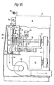
- FIGS 1A and 1B provide an overall view of the tow cutter assembly 10, in which the tow cutter is horizontally oriented rather than vertically oriented, as has been conventional.
- a drive motor 12 drives a timing belt 14 which is operatively connected to a drive shaft 16 which is mounted in bearings 17 and is connected to a cutter reel assembly 18.
- Cooperatively positioned for normal interaction with the cutter reel assembly 18 is a pressure roller 20, mounted on arms 24, which may be adjusted in a conventional manner by a pressure roller adjustment assembly 22.
- the space between inner plate 38 and the outer ring 40 is decreased, thereby decreasing the transit distance from the innermost edges of the cutter blades 44 to the outermost restricted diameter of ring 40.
- This narrowing of the spaces between inner plate 38 and the outer ring 40 is practical because the higher the speed of spinning and drawing, the smaller the tows may be to accomplish the desired production rate.
- the diameter of Dl, the inner cylindrical surface 48 is equal to or only slightly less than the diameter D2 of the circle defined by the path of movement of the cutting edges 45 of cutting blades 44. A difference in diameter of less than 15 mm is deemed satisfactory.
- the blade support posts 46 can be machined from larger sections of either round or rectangular material, so as to fit accurately against the cylindrical inner surface 48 of outer ring 40, against which they are held by fasteners 54.
- Blade support posts 46 With reference to Figures 2 and 4, it can be seen that the portion of blade support posts 46 intermediate inner plate 38 and outer ring 40 are bevelled so that they flare outwardly away from the portion of cutting blade 44 intermediate inner disc 38 and outer ring 40, to facilitate the smooth transfer of cut staple from the blade edges to the inside of reel assembly 18.
- Blade support posts 46 have a longitudinal blade slot 58 within which cutter blade 44 is seated.
- the outer ring has an inner conical surface 52 which terminates in the outer lip 50 which projects axially beyond the distance required for structural support for outer ring 40.
- Outer ring 40 thus provides a conventional radial flange 55 for retaining uncut tow within the reel assembly 18 and the axially extending lip 50, said flange and lip joining on the outer surface of ring 40 to form a shoulder 51.
- a staple receiving hopper 28 is provided which fits closely adjacent to shoulder 51, such that lip 50 extends within the opening 53 in the hopper 28, which is desirable for two reasons.
- the conical surface 52 supports the fibres as they flow out of the reel assembly 18 and directs them into hopper 28. Therefore the conical surface 52 must extend inside hopper 28 so that the cut fibres are guided into hopper 28 without the possibility of being thrown out through the space between outer ring 40 and hopper 28.
- the conical surface 52 supports the fibres that may be cut at one end only, i.e. by only one blade.
- Such fibres would be lying against the conical surface 52 under the influence of centrifugal force and if such fibres extended into the airstream within hopper 28 whereby there exists very high turbulence they would entangle cut staple passing thereby in close proximity and would also pull their uncut ends circumferentially across the adjacent blade resulting in unequal staple lengths. Therefore the distance from the cutting edge of the cutter blade 44 to the outer portion of the conical surface 52 is designed to exceed the circumferential spacing between the cutter blades of the reel assembly 18.
- Hopper 28 fits snugly about the shoulder 51 formed by lip 50, to produce, in effect, a labyrinth seal, which not only causes proper discharge of the cut fibre into hopper 28, but also allows the development of sub-atmospheric pressure inside the reel assembly 18.
- Discharge hopper 28 has a lower discharge outlet to a lower discharge section 30 which in turn communicates with a fan or air pump 32 which induces a sub-atmospheric pressure that reaches into the blade area of the reel assembly 18.
- Hopper 28 has a cover section 25 and a mounting plate 27 and is mounted on hinges 29, which are aligned in a plane which extends through the labyrinth seal formed between the outer ring 40 and discharge hopper 28, to allow the discharge hopper 28 to be swung away from the reel assembly 18, thereby allowing inspection of reel assembly 18 or removal and reinstallation of reel assembly 18 in a rapid and efficient manner.
- a seal 31 which is preferably formed of a resilient flexible material to provide a substantially uniform and long-life seal.
- Hopper 28 will provide the outer seal for the reel assembly 18, and an intermediate panel 26 positioned behind reel assembly 18 and pressure roller 20 separates these mechanisms from the power driving section of the tow cutter 10 and provides a substantially sealed area about the reel assembly 18.
- the sub-atmospheric pressure induced inside the reel assembly 18 allows the tow cutter 19 to be self-threading at the high speed at which the tow is being fed into cutter 10.
- the spinning and drawing operations cannot be stopped without a costly restart process. Therefore, the cutter must be threaded up "on the fly", i.e. while rotaing. Conventionally this is accomplished with the use of aspirator guns that use the injector principle to collect the tow into the gun barrel and deposit it through a connecting pipe system into a waste collector while switching from one cutting machine to another or while a relatively short shutdown occurs during rethreading when only a single cutter is being used.
- sub-atmospheric pressure within reel assembly 18 great enough to overcome the centrifugal fan action of the fast rotating cutter blades 44, air is introduced inwardly through the spaces between blades 44, so that a tow introduced into the space between the outer ring 40 and the inner plate 38 outside cutter blades 44 is indeed pulled toward blades 44 and wraps itself around the cutting edges of blades 44, thus the cutting operation automatically commences when the speed of the tow being fed into the cutter is coordinated with the speed of rotation of the cutter reel assembly 18.
- the sub-atmospheric pressure within reel assembly 18 and hopper 28 induces air currents through the labyrinth seal between the reel assembly 18 and hopper 28 after the cutter blades 44 have been covered by the wrapped tow. These air currents tend to lift the cut fibre off the conical surface 52 and cause the fibres to follow the airstream out of hopper 28 into lower discharge section 30.
- a tubular tow inlet housing 36 may be provided which is open to the outside of the cabinet 11 of tow cutter 18 to define an inlet 60.
- the discharge end 62 of the inlet housing 36 is located in close proximity to the reel assembly 18, such that tow directed therethrough is directed between the flanges of the reel assembly 18.
- This outlet 62 has an arcuate terminus 64 which fits in close relation to the flanges of reel 18, so that on the initial thread-up, when the reel 18 has no tow wrapped around cutter blades 44, the sub-atmospheric pressure within reel 18 will create an airstream flowing through tow inlet housing 36, which will enable the tow to be threaded up at high speeds with the use of an aspirator gun.
- the aspirator gun must be placed in close proximity to inlet 60 so that the air currents through tow inlet housing 36 may take the tow away from the gun and into the housing.
- the discharge opening of arcuate terminus 64 must be smaller than the distance between the inner plate 38 and outer ring 40 in order for the tow to be properly fed onto reel assembly 18.
- the seal 31, the labyrinth seal between outer ring 40 and hopper 28, and the seal provided by intermediate panel 26 provides a housing which is sufficiently airtight that the sub-atmospheric pressure within this assembly will force air to be taken in through tow inlet housing 36.
- Tow inlet housing 36 is mounted on a hinge 65 and urged into close proximity at the arcuate terminus 64 thereof to reel assembly 18 by a spring 66, to allow housing 36 to pivot away from reel assembly 18 when an occasional tow wrap-up on the reel occurs, thereby avoiding damage to the housing.
- tow inlet housing 36 may also be manually pivoted away from reel assembly 18 for convenience in removing and reinstalling the cutter reel assembly 18.
- hinged tow inlet housing 36 is designed and positioned relative to the tow inlet guides 34 and tow guide wheel 35 that a second tow may be brought in close proximity with inlet 60 to tow inlet housing 36 by means of an aspirator gun. The air pressure of the aspirator gun may then be reduced so that the second tow will be mechanically entrained by the first tow as it enters tow inlet housing 36.
- tow inlet housing 36 The converging surfaces of tow inlet housing 36 will force the second tow to be entrapped between the first tow and the tow wrapped around reel assembly 18, so that the second tow will be positively pulled onto reel assembly 16.
- the discharge opening of the tow inlet housing should be slightly narrower than the distance between the flanges of the reel.
- the overall configuration of tow inlet housing 36 is such that inlet end 60 is larger than discharge end 62 with the body of tow inlet housing 36 tapering from inlet 60 to discharge end 62 at its arcuate terminus 64.
- guides 34 and a guide wheel 35 are properly positioned to prevent the two tows hereinabove described from touching each other until the moment that the second tow is released by the aspirator gun into inlet 60.
- pressure roller 20 has a diameter which is greater than one-half the diameter of reel assembly 18. At the very high speeds utilized by the cutter of the invention, the cutting action takes place very quickly, and fibre fusing can result unless the impact forces can be reduced.
- the function of the larger diameter of pressure roller 20 is to provide a more gradual cutting action as the convergence between the periphery of pressure roller 20 and the locus of the cutting edges of the cutting blades 44 becomes more gradual as the pressure roller diameter increases.
- Cutter reel assembly 18 is rotated by drive motor 12, through timing belt 14 and drive shaft 16.
- the cutter reel assembly 18 is brought up to the desired rotational speed as fan 32 induces a sub-atmospheric pressure inwardly of the blades 44 of reel assembly 18, which induces an airflow through tow inlet housing 36.
- This airflow is utilized to introduce the free end of a tow into the reel assembly adjacent the arcuate terminus 64 of tow inlet housing 36.
- the sub-atmospheric pressure and the rotating cutter blades entrain the tow and wrap it around the reel assembly 18 thereby drawing the tow over guide wheel 35, past tow guide 34, and through tow inlet housing 36.
- the tow is wrapped around reel assembly 18 to a sufficient depth as to engage pressure roller 20 which forces the wrapped tow inward, cutting the innermost tow at the locus of the periphery of pressure roller 20 and cutter blades 44.
- the cut tow or staple then flows inward of reel assembly 18 over the bevelled blade support surfaces 56 to the conical surface 52 of axially extending lip 50, whereby said cut staple is discharged into discharge hopper 28.
- Air currents entering via the labyrinth seal between outer ring 40 and discharge hopper 28 lift the cut staple from the conical surface 52 and assist in directing it into the air pathway from ring 40 through discharge hopper 28 into lower discharge section 30. It is then transported to a suitable location for the next step in the processing of the fibres into a finished textile.
- To introduce a second tow to the cutter reel assembly 18 the second tow is discharged into inlet 60 of tow inlet housing 36 so as to be mechanically entrained by the first tow about cutter reel assembly 18 and is thereby positively drawn onto reel
- Centrifugal loading on both the tow cutter reel assembly and the uncut tow thereon is achieved by reducing the distance within the reel that the cut tow is required to traverse, and by reducing the accumulation of cut staple within the reel assembly through the use of advantageously bevelled blade support posts and an outer ring having an inner diameter only slightly smaller than the diameter of the cutting edges of the cutting blades.
- the ring 40 also has a conically shaped outer lip which effects the transfer of cut staple from the reel assembly into a discharge hopper.
- the tow cutter provides an improvement in introducing tow into the tow cutter such that the tow cutter may be threaded up while rotating at initial start-up due to the advantageous utilization of sub-atmospheric pressure within the reel assembly or may be automatically threaded during operation by a second tow mechanically entrained to a first tow previously wrapped about reel assembly 18.
- the invention also improves the cutting action of previously known tow cutters by providing for a more gradual cutting action at high operating speeds thereby reducing fibre fusing which results from high impact forces between the pressure roller and the cutter blades.
Abstract

Description
- This invention relates to an outside-in tow cutter for cutting fibrous material into shorter lengths for use in the textile industry.
- Modern devices for cutting fibrous material tow, in the textile industry, are usually of the outside-in cutter type shown in U.S. Patent 3,485,120. Such apparatus are designed so that a number of layers of uncut tow are wrapped spirally on the radially out-turned cutting edges of a plurality of blades whose edges are uniformly spaced from the centre of rotation of the reel upon which the blades are mounted. Such reels comprise an inner circular plate connected to a central drive shaft for rotation therewith, an outer ring axially spaced from the inner plate and a plurality of circumferentially spaced, generally radially extending cutter blades mounted between said inner plate and outer ring, with their cutting edges outermost.
- The disc and ring thus form flanges between which the tow wound on the reel is held. A cylindrical pressure roller fits snugly between the flanges and its periphery is held at a uniform distance from the cutting edges of the blades, thereby forcing the tow radially inward to the cutting blades. Such machines were initially used for process speeds up to as high as 500 meters per minute; however, with the development of higher speed spin-draw lines in the man-made fibre industry, speeds have increased substantially above 500 metres per minute. Centrifugal force has become a major factor in the function of known cutters, since with higher rotational speeds the mass of uncut tow plus the mass of cut staple inside the cutting edges is very significant.
- It is now proposed, according to the invention, that the inner surface of the outer ring should have a diameter which is only equal to or only slightly less than the diameter of the cylindrical surface along which said cutting edges move.
- With such a construction the mass of cut fibrous material carried by the reel during operation can be reduced thereby reducing the centrifugal forces and consequent stress placed on the uncut tow, so that the tow cutter is capable of operating at speeds in excess of 2,000 metres per minute.
- Advantageously, the outer ring diameter is less than 15 mm smaller than the diameter of the cylindrical surface along which the cutting edges move.
- The invention also provides an apparatus for cutting fibre into short lengths, the apparatus comprising a cutter of the invention, feed means for introducing cut fibre into said reel between said inner plate and said outer ring, a pressure roller having a periphery positioned between the inner plate and the outer ring to urge said fibre introduced into said reel towards the cutting blades, a housing including a portion closely adjacent the outer ring and means for sustaining a sub-atmospheric pressure within said housing and said reel such that air is drawn into the housing via the feed means.
- Disposed in close proximity to said reel advantageously is an input housing which is cooperatively position to introduce tow into the reel so that the air currents generated by the sub-atmospheric pressure carry the tow onto the reel until successive layers are accumulated thereon. In order to minimize impact forces heretofore encountered, the diameter of the pressure roller is preferably increased to exceed one-half the diameter of the cutter reel.
- In order that the invention may more readily be understood, the following description is given, merely by way of example, reference being made to the accompanying drawings, in which:-
- Fig. 1A is a front elevational view of one embodiment of tow cutter apparatus according to the invention, with its housing broken away and in section;
- Fig. 1B is a side elevational view of the apparatus of Figure lA, with parts being broken away and in section;
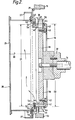
- Fig. 2 is an enlarged section of the reel assembly of the apparatus and taken along the line 2-2 of Figure lA, with parts being omitted for the sake of clarity;
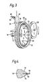
- Fig. 3 is a perspective view depicting the tow inlet housing in conjunction with the reel assembly and pressure roller; and
- Fig. 4 is a sectional view through the cutter blade and its support post.
- Figures 1A and 1B provide an overall view of the
tow cutter assembly 10, in which the tow cutter is horizontally oriented rather than vertically oriented, as has been conventional. Adrive motor 12 drives atiming belt 14 which is operatively connected to adrive shaft 16 which is mounted inbearings 17 and is connected to acutter reel assembly 18. Cooperatively positioned for normal interaction with thecutter reel assembly 18 is apressure roller 20, mounted onarms 24, which may be adjusted in a conventional manner by a pressureroller adjustment assembly 22. - In order to overcome the centrifugal loading inherent in a cutter reel of a tow cutter it is necessary to reduce the mass of fibrous material being carried by the reel. As seen in Figure 2, this can be achieved by reducing the distance between the components of the
cutter reel assembly 18, which includes aninner plate 38 which is connected by amounting flange 39 to adrive shaft 16. Theinner plate 38 and anouter ring 40 have positioned therebetween a plurality of circumferentially spacedcutter blades 44, each mounted in ablade support post 46 and held in place by anannular blade retainer 42, which is attached to theinner plate 38 bybolts 43. Theblade support posts 46 are secured tightly in holes in theinner plate 38 and are bolted or otherwise attached to the cylindricalinner surface 48 of theouter ring 40 byradial fasteners 54 or other attaching means. - To reduce the centrifugal loading on the cutter reel assembly, the space between
inner plate 38 and theouter ring 40 is decreased, thereby decreasing the transit distance from the innermost edges of thecutter blades 44 to the outermost restricted diameter ofring 40. This narrowing of the spaces betweeninner plate 38 and theouter ring 40 is practical because the higher the speed of spinning and drawing, the smaller the tows may be to accomplish the desired production rate. - It is common in conventional tow cutters of this type for an accummulation of staple to build up in a somewhat triangular shape inwardly of the blades as the staple slides past the inner
cylindrical surface 48 of thering 40. According to the invention, the diameter of Dl, the innercylindrical surface 48 is equal to or only slightly less than the diameter D2 of the circle defined by the path of movement of thecutting edges 45 ofcutting blades 44. A difference in diameter of less than 15 mm is deemed satisfactory. With this construction theblade support posts 46 can be machined from larger sections of either round or rectangular material, so as to fit accurately against the cylindricalinner surface 48 ofouter ring 40, against which they are held byfasteners 54. With reference to Figures 2 and 4, it can be seen that the portion ofblade support posts 46 intermediateinner plate 38 andouter ring 40 are bevelled so that they flare outwardly away from the portion ofcutting blade 44 intermediateinner disc 38 andouter ring 40, to facilitate the smooth transfer of cut staple from the blade edges to the inside ofreel assembly 18.Blade support posts 46 have alongitudinal blade slot 58 within whichcutter blade 44 is seated. - As seen in Figure 2, the outer ring has an inner
conical surface 52 which terminates in theouter lip 50 which projects axially beyond the distance required for structural support forouter ring 40.Outer ring 40 thus provides a conventionalradial flange 55 for retaining uncut tow within thereel assembly 18 and the axially extendinglip 50, said flange and lip joining on the outer surface ofring 40 to form ashoulder 51. - A staple receiving
hopper 28 is provided which fits closely adjacent toshoulder 51, such thatlip 50 extends within theopening 53 in thehopper 28, which is desirable for two reasons. Firstly, theconical surface 52 supports the fibres as they flow out of thereel assembly 18 and directs them intohopper 28. Therefore theconical surface 52 must extend insidehopper 28 so that the cut fibres are guided intohopper 28 without the possibility of being thrown out through the space betweenouter ring 40 and hopper 28. Secondly, theconical surface 52 supports the fibres that may be cut at one end only, i.e. by only one blade. Such fibres would be lying against theconical surface 52 under the influence of centrifugal force and if such fibres extended into the airstream withinhopper 28 whereby there exists very high turbulence they would entangle cut staple passing thereby in close proximity and would also pull their uncut ends circumferentially across the adjacent blade resulting in unequal staple lengths. Therefore the distance from the cutting edge of thecutter blade 44 to the outer portion of theconical surface 52 is designed to exceed the circumferential spacing between the cutter blades of thereel assembly 18. - Hopper 28 fits snugly about the
shoulder 51 formed bylip 50, to produce, in effect, a labyrinth seal, which not only causes proper discharge of the cut fibre intohopper 28, but also allows the development of sub-atmospheric pressure inside thereel assembly 18.Discharge hopper 28 has a lower discharge outlet to alower discharge section 30 which in turn communicates with a fan orair pump 32 which induces a sub-atmospheric pressure that reaches into the blade area of thereel assembly 18. Hopper 28 has acover section 25 and amounting plate 27 and is mounted onhinges 29, which are aligned in a plane which extends through the labyrinth seal formed between theouter ring 40 anddischarge hopper 28, to allow thedischarge hopper 28 to be swung away from thereel assembly 18, thereby allowing inspection ofreel assembly 18 or removal and reinstallation ofreel assembly 18 in a rapid and efficient manner. In order to maintain the sub-atmospheric pressure within thereel assembly 18, there is provided, between the bottom ofhopper 28 and thelower discharge section 30, aseal 31, which is preferably formed of a resilient flexible material to provide a substantially uniform and long-life seal. Hopper 28 will provide the outer seal for thereel assembly 18, and anintermediate panel 26 positioned behindreel assembly 18 andpressure roller 20 separates these mechanisms from the power driving section of thetow cutter 10 and provides a substantially sealed area about thereel assembly 18. - The sub-atmospheric pressure induced inside the
reel assembly 18 allows the tow cutter 19 to be self-threading at the high speed at which the tow is being fed intocutter 10. In the spin-draw processes producing the high speed tows, the spinning and drawing operations cannot be stopped without a costly restart process. Therefore, the cutter must be threaded up "on the fly", i.e. while rotaing. Conventionally this is accomplished with the use of aspirator guns that use the injector principle to collect the tow into the gun barrel and deposit it through a connecting pipe system into a waste collector while switching from one cutting machine to another or while a relatively short shutdown occurs during rethreading when only a single cutter is being used. By providing sub-atmospheric pressure withinreel assembly 18 great enough to overcome the centrifugal fan action of the fast rotatingcutter blades 44, air is introduced inwardly through the spaces betweenblades 44, so that a tow introduced into the space between theouter ring 40 and theinner plate 38 outsidecutter blades 44 is indeed pulled towardblades 44 and wraps itself around the cutting edges ofblades 44, thus the cutting operation automatically commences when the speed of the tow being fed into the cutter is coordinated with the speed of rotation of thecutter reel assembly 18. Secondly, the sub-atmospheric pressure withinreel assembly 18 and hopper 28 induces air currents through the labyrinth seal between thereel assembly 18 and hopper 28 after thecutter blades 44 have been covered by the wrapped tow. These air currents tend to lift the cut fibre off theconical surface 52 and cause the fibres to follow the airstream out ofhopper 28 intolower discharge section 30. - A tubular
tow inlet housing 36, shown in Figure 3, may be provided which is open to the outside of thecabinet 11 oftow cutter 18 to define aninlet 60. The discharge end 62 of theinlet housing 36 is located in close proximity to thereel assembly 18, such that tow directed therethrough is directed between the flanges of thereel assembly 18. This outlet 62 has anarcuate terminus 64 which fits in close relation to the flanges ofreel 18, so that on the initial thread-up, when thereel 18 has no tow wrapped aroundcutter blades 44, the sub-atmospheric pressure withinreel 18 will create an airstream flowing throughtow inlet housing 36, which will enable the tow to be threaded up at high speeds with the use of an aspirator gun. The aspirator gun must be placed in close proximity toinlet 60 so that the air currents throughtow inlet housing 36 may take the tow away from the gun and into the housing. - The discharge opening of
arcuate terminus 64 must be smaller than the distance between theinner plate 38 andouter ring 40 in order for the tow to be properly fed ontoreel assembly 18. Theseal 31, the labyrinth seal betweenouter ring 40 andhopper 28, and the seal provided byintermediate panel 26 provides a housing which is sufficiently airtight that the sub-atmospheric pressure within this assembly will force air to be taken in throughtow inlet housing 36. Towinlet housing 36 is mounted on ahinge 65 and urged into close proximity at thearcuate terminus 64 thereof to reelassembly 18 by aspring 66, to allowhousing 36 to pivot away fromreel assembly 18 when an occasional tow wrap-up on the reel occurs, thereby avoiding damage to the housing. Of course,tow inlet housing 36 may also be manually pivoted away fromreel assembly 18 for convenience in removing and reinstalling thecutter reel assembly 18. - It is sometimes necessary to thread up a second tow while a first tow is already running on
reel assembly 18. Under such conditions, the first tow will have blocked off the air movement betweenblades 44 of thereel assembly 18 and therefore the sub-atmospheric pressure used to thread up the first tow is not available for threading up the second tow. However, hingedtow inlet housing 36 is designed and positioned relative to the tow inlet guides 34 andtow guide wheel 35 that a second tow may be brought in close proximity withinlet 60 to towinlet housing 36 by means of an aspirator gun. The air pressure of the aspirator gun may then be reduced so that the second tow will be mechanically entrained by the first tow as it enterstow inlet housing 36. The converging surfaces oftow inlet housing 36 will force the second tow to be entrapped between the first tow and the tow wrapped aroundreel assembly 18, so that the second tow will be positively pulled ontoreel assembly 16. To accomplish this, the discharge opening of the tow inlet housing should be slightly narrower than the distance between the flanges of the reel. Of course, the overall configuration oftow inlet housing 36 is such thatinlet end 60 is larger than discharge end 62 with the body oftow inlet housing 36 tapering frominlet 60 to discharge end 62 at itsarcuate terminus 64. In addition guides 34 and aguide wheel 35 are properly positioned to prevent the two tows hereinabove described from touching each other until the moment that the second tow is released by the aspirator gun intoinlet 60. - With reference to Figure 1A it can be seen that
pressure roller 20 has a diameter which is greater than one-half the diameter ofreel assembly 18. At the very high speeds utilized by the cutter of the invention, the cutting action takes place very quickly, and fibre fusing can result unless the impact forces can be reduced. The function of the larger diameter ofpressure roller 20 is to provide a more gradual cutting action as the convergence between the periphery ofpressure roller 20 and the locus of the cutting edges of thecutting blades 44 becomes more gradual as the pressure roller diameter increases. - In operation the device is controlled from a
control panel 70 mounted oncabinet 11 which encloses all of the hereinabove described mechanical linkages.Cutter reel assembly 18 is rotated bydrive motor 12, throughtiming belt 14 and driveshaft 16. To initiate operation, thecutter reel assembly 18 is brought up to the desired rotational speed asfan 32 induces a sub-atmospheric pressure inwardly of theblades 44 ofreel assembly 18, which induces an airflow throughtow inlet housing 36. This airflow is utilized to introduce the free end of a tow into the reel assembly adjacent thearcuate terminus 64 oftow inlet housing 36. The sub-atmospheric pressure and the rotating cutter blades entrain the tow and wrap it around thereel assembly 18 thereby drawing the tow overguide wheel 35,past tow guide 34, and throughtow inlet housing 36. - The tow is wrapped around
reel assembly 18 to a sufficient depth as to engagepressure roller 20 which forces the wrapped tow inward, cutting the innermost tow at the locus of the periphery ofpressure roller 20 andcutter blades 44. The cut tow or staple then flows inward ofreel assembly 18 over the bevelled blade support surfaces 56 to theconical surface 52 of axially extendinglip 50, whereby said cut staple is discharged intodischarge hopper 28. Air currents entering via the labyrinth seal betweenouter ring 40 anddischarge hopper 28 lift the cut staple from theconical surface 52 and assist in directing it into the air pathway fromring 40 throughdischarge hopper 28 intolower discharge section 30. It is then transported to a suitable location for the next step in the processing of the fibres into a finished textile. To introduce a second tow to thecutter reel assembly 18 the second tow is discharged intoinlet 60 oftow inlet housing 36 so as to be mechanically entrained by the first tow aboutcutter reel assembly 18 and is thereby positively drawn ontoreel assembly 18. - Centrifugal loading on both the tow cutter reel assembly and the uncut tow thereon is achieved by reducing the distance within the reel that the cut tow is required to traverse, and by reducing the accumulation of cut staple within the reel assembly through the use of advantageously bevelled blade support posts and an outer ring having an inner diameter only slightly smaller than the diameter of the cutting edges of the cutting blades. The
ring 40 also has a conically shaped outer lip which effects the transfer of cut staple from the reel assembly into a discharge hopper. Further, the tow cutter provides an improvement in introducing tow into the tow cutter such that the tow cutter may be threaded up while rotating at initial start-up due to the advantageous utilization of sub-atmospheric pressure within the reel assembly or may be automatically threaded during operation by a second tow mechanically entrained to a first tow previously wrapped aboutreel assembly 18. The invention also improves the cutting action of previously known tow cutters by providing for a more gradual cutting action at high operating speeds thereby reducing fibre fusing which results from high impact forces between the pressure roller and the cutter blades.
Claims (10)
Applications Claiming Priority (2)
| Application Number | Priority Date | Filing Date | Title |
|---|---|---|---|
| US06/676,521 US4569264A (en) | 1984-11-29 | 1984-11-29 | Apparatus for cutting elongated material into shorter lengths |
| US676521 | 1984-11-29 |
Publications (3)
| Publication Number | Publication Date |
|---|---|
| EP0183543A2 true EP0183543A2 (en) | 1986-06-04 |
| EP0183543A3 EP0183543A3 (en) | 1987-05-20 |
| EP0183543B1 EP0183543B1 (en) | 1990-01-31 |
Family
ID=24714872
Family Applications (1)
| Application Number | Title | Priority Date | Filing Date |
|---|---|---|---|
| EP85308629A Expired - Lifetime EP0183543B1 (en) | 1984-11-29 | 1985-11-27 | Apparatus for cutting elongated material into shorter lengths |
Country Status (7)
| Country | Link |
|---|---|
| US (1) | US4569264A (en) |
| EP (1) | EP0183543B1 (en) |
| JP (1) | JPS61160424A (en) |
| CN (1) | CN1008453B (en) |
| CA (1) | CA1252037A (en) |
| DE (1) | DE3575745D1 (en) |
| MX (1) | MX162424A (en) |
Families Citing this family (15)
| Publication number | Priority date | Publication date | Assignee | Title |
|---|---|---|---|---|
| US4612842A (en) * | 1985-08-14 | 1986-09-23 | E. I. Du Pont De Nemours And Company | Apparatus for cutting filamentary material |
| US4771665A (en) * | 1987-08-28 | 1988-09-20 | Lummus Industries, Inc. | Blade quality monitor |
| US5003855A (en) * | 1989-01-23 | 1991-04-02 | Ciupak Lawrence F | Chopper with auto feed |
| ES2092706T3 (en) * | 1992-02-08 | 1996-12-01 | Hoechst Ag | PROCEDURE AND DEVICE FOR CONTINUOUSLY CUTTING BAND OR ROPE MATERIAL. |
| US6029552A (en) * | 1997-06-05 | 2000-02-29 | Harris; Lowell D. | Method and apparatus for cutting fiber tow inside-out |
| US6299097B1 (en) | 1999-12-20 | 2001-10-09 | Corning Incorporated | Anti-whip fiber cutter |
| CN1329155C (en) * | 2004-03-19 | 2007-08-01 | 宁波韵升股份有限公司 | Multicutter technique for cutting inner circle and device |
| US20080210066A1 (en) * | 2007-03-02 | 2008-09-04 | Russell Donovan Arterburn | Method for chopping unwound items and coated chopper blades |
| CN202114746U (en) * | 2011-04-08 | 2012-01-18 | 福建海源自动化机械股份有限公司 | Continuously and accurately measured continuous fiber fixed length cutting device |
| US20190233982A1 (en) * | 2018-01-31 | 2019-08-01 | Parkdale Incorporated | Multi-length, multi-denier, multi-cross section fiber blend yarn |
| CN109094150B (en) * | 2018-06-15 | 2020-08-25 | 阿斯福特纺织(漳州)有限公司 | Forming process of high-performance knitted fabric with good uniformity |
| CN108909134B (en) * | 2018-06-15 | 2020-06-23 | 阿斯福特纺织(漳州)有限公司 | Forming process of chemical fiber blanket |
| US11788210B1 (en) | 2018-09-10 | 2023-10-17 | Under Armour, Inc. | Athletic apparel |
| CN112047189B (en) * | 2020-08-29 | 2022-06-24 | 河南交通职业技术学院 | Rotary basalt fiber automatic cutting machine |
| CN112481743A (en) * | 2020-12-01 | 2021-03-12 | 安徽同光邦飞生物科技有限公司 | Short fiber cutting machine |
Citations (4)
| Publication number | Priority date | Publication date | Assignee | Title |
|---|---|---|---|---|
| FR2141657A1 (en) * | 1971-06-14 | 1973-01-26 | Lummus Industries | |
| FR2242491A1 (en) * | 1973-08-30 | 1975-03-28 | Neumuenster Masch App | |
| FR2494167A1 (en) * | 1980-11-19 | 1982-05-21 | Lummus Industries | INTERNAL-OUTSIDE CUTTING DEVICE FOR EXTENDED MATERIALS SUCH AS THE CUTTER |
| US4391169A (en) * | 1980-08-11 | 1983-07-05 | Hartford Fibres, Ltd. | Cutter with angular blades and method for cutting rope therewith |
Family Cites Families (5)
| Publication number | Priority date | Publication date | Assignee | Title |
|---|---|---|---|---|
| US3485120A (en) * | 1966-09-08 | 1969-12-23 | Eastman Kodak Co | Method and apparatus for cutting elongated material |
| NL7415905A (en) * | 1974-12-06 | 1976-06-09 | Akzo Nv | METHOD AND DEVICE FOR CUTTING FIBERS. |
| US4169398A (en) * | 1975-09-18 | 1979-10-02 | Imperial Chemical Industries, Inc. | Filament cutting |
| US4300422A (en) * | 1980-05-27 | 1981-11-17 | E. I. Du Pont De Nemours And Company | Apparatus for cutting filamentary material |
| US4515054A (en) * | 1983-03-07 | 1985-05-07 | Celanese Corporation | Cutter wheel for cutting continuous tow |
-
1984
- 1984-11-29 US US06/676,521 patent/US4569264A/en not_active Expired - Fee Related
-
1985
- 1985-11-26 MX MX726A patent/MX162424A/en unknown
- 1985-11-27 DE DE8585308629T patent/DE3575745D1/en not_active Expired - Fee Related
- 1985-11-27 CA CA000496309A patent/CA1252037A/en not_active Expired
- 1985-11-27 JP JP60267034A patent/JPS61160424A/en active Pending
- 1985-11-27 EP EP85308629A patent/EP0183543B1/en not_active Expired - Lifetime
- 1985-11-29 CN CN85108652.7A patent/CN1008453B/en not_active Expired
Patent Citations (4)
| Publication number | Priority date | Publication date | Assignee | Title |
|---|---|---|---|---|
| FR2141657A1 (en) * | 1971-06-14 | 1973-01-26 | Lummus Industries | |
| FR2242491A1 (en) * | 1973-08-30 | 1975-03-28 | Neumuenster Masch App | |
| US4391169A (en) * | 1980-08-11 | 1983-07-05 | Hartford Fibres, Ltd. | Cutter with angular blades and method for cutting rope therewith |
| FR2494167A1 (en) * | 1980-11-19 | 1982-05-21 | Lummus Industries | INTERNAL-OUTSIDE CUTTING DEVICE FOR EXTENDED MATERIALS SUCH AS THE CUTTER |
Also Published As
| Publication number | Publication date |
|---|---|
| EP0183543A3 (en) | 1987-05-20 |
| MX162424A (en) | 1991-05-10 |
| CN1008453B (en) | 1990-06-20 |
| CA1252037A (en) | 1989-04-04 |
| US4569264A (en) | 1986-02-11 |
| JPS61160424A (en) | 1986-07-21 |
| CN85108652A (en) | 1986-09-24 |
| DE3575745D1 (en) | 1990-03-08 |
| EP0183543B1 (en) | 1990-01-31 |
Similar Documents
| Publication | Publication Date | Title |
|---|---|---|
| EP0183543B1 (en) | Apparatus for cutting elongated material into shorter lengths | |
| US3834145A (en) | Open-end spinning of textile yarns | |
| US4516396A (en) | Open end yarn spinning apparatus | |
| EP2799380B1 (en) | Winder | |
| US3141201A (en) | Method and means for laying out slivers and the like | |
| CN102808248B (en) | Open-end spinning device | |
| US3845612A (en) | Spinning apparatus | |
| US4976099A (en) | Sliver feeding and opening device of an open end spinning machine | |
| US5465567A (en) | Fiber opening device for separating individual fibers from a fiber sliver | |
| JPH0372725B2 (en) | ||
| US5626011A (en) | Method for joining a thread in a device for manufacturing a twisted yarn by an integrated spinning and twisting process as well as a device for performing the method | |
| US4237758A (en) | Process and apparatus for shredding fibre tows into staple fibres | |
| US4784344A (en) | Yarn withdrawal apparatus and method | |
| JPS63203827A (en) | Open end rotor fine spinning frame | |
| JPS5988932A (en) | Jet spinning apparatus | |
| US5187930A (en) | Arrangement for spinning staple fibers into a yarn | |
| US3882666A (en) | Method of spinning yarns in spinning turbines | |
| US3778990A (en) | Device for open end spinning | |
| US5628177A (en) | Method and device for manufacturing a twisted yarn in an integrated spin-twisting process according to the two-for-one twisting method from dissolved fiber material | |
| US5222352A (en) | Process and an arrangement for spinning staple fibers into a yarn | |
| US5481862A (en) | Pneumatically operated debris removal device for an open-end spinning device | |
| US4535663A (en) | Apparatus for removing cut staple | |
| JPH07508315A (en) | Open-end spinning method and device | |
| US6311468B1 (en) | Device for producing a twisted yarn by an integrated spinning and twisting process as well as fiber feed tube | |
| CS244401B2 (en) | Staple fibres spinning device |
Legal Events
| Date | Code | Title | Description |
|---|---|---|---|
| PUAI | Public reference made under article 153(3) epc to a published international application that has entered the european phase |
Free format text: ORIGINAL CODE: 0009012 |
|
| AK | Designated contracting states |
Kind code of ref document: A2 Designated state(s): BE DE FR GB IT |
|
| PUAL | Search report despatched |
Free format text: ORIGINAL CODE: 0009013 |
|
| AK | Designated contracting states |
Kind code of ref document: A3 Designated state(s): BE DE FR GB IT |
|
| 17P | Request for examination filed |
Effective date: 19871104 |
|
| 17Q | First examination report despatched |
Effective date: 19881207 |
|
| GRAA | (expected) grant |
Free format text: ORIGINAL CODE: 0009210 |
|
| AK | Designated contracting states |
Kind code of ref document: B1 Designated state(s): BE DE FR GB IT |
|
| ITF | It: translation for a ep patent filed |
Owner name: PROPRIA PROTEZIONE PROPR. IND. |
|
| ET | Fr: translation filed | ||
| REF | Corresponds to: |
Ref document number: 3575745 Country of ref document: DE Date of ref document: 19900308 |
|
| PLBE | No opposition filed within time limit |
Free format text: ORIGINAL CODE: 0009261 |
|
| STAA | Information on the status of an ep patent application or granted ep patent |
Free format text: STATUS: NO OPPOSITION FILED WITHIN TIME LIMIT |
|
| 26N | No opposition filed | ||
| ITTA | It: last paid annual fee | ||
| PGFP | Annual fee paid to national office [announced via postgrant information from national office to epo] |
Ref country code: FR Payment date: 19931110 Year of fee payment: 9 |
|
| PGFP | Annual fee paid to national office [announced via postgrant information from national office to epo] |
Ref country code: GB Payment date: 19931117 Year of fee payment: 9 |
|
| PGFP | Annual fee paid to national office [announced via postgrant information from national office to epo] |
Ref country code: DE Payment date: 19931123 Year of fee payment: 9 |
|
| PGFP | Annual fee paid to national office [announced via postgrant information from national office to epo] |
Ref country code: BE Payment date: 19940105 Year of fee payment: 9 |
|
| PG25 | Lapsed in a contracting state [announced via postgrant information from national office to epo] |
Ref country code: GB Effective date: 19941127 |
|
| PG25 | Lapsed in a contracting state [announced via postgrant information from national office to epo] |
Ref country code: BE Effective date: 19941130 |
|
| BERE | Be: lapsed |
Owner name: LUMMUS INDUSTRIES INC. Effective date: 19941130 |
|
| GBPC | Gb: european patent ceased through non-payment of renewal fee |
Effective date: 19941127 |
|
| PG25 | Lapsed in a contracting state [announced via postgrant information from national office to epo] |
Ref country code: FR Effective date: 19950731 |
|
| PG25 | Lapsed in a contracting state [announced via postgrant information from national office to epo] |
Ref country code: DE Effective date: 19950801 |
|
| REG | Reference to a national code |
Ref country code: FR Ref legal event code: ST |