EP0183522B1 - Automobile antenna device - Google Patents
Automobile antenna device Download PDFInfo
- Publication number
- EP0183522B1 EP0183522B1 EP85308573A EP85308573A EP0183522B1 EP 0183522 B1 EP0183522 B1 EP 0183522B1 EP 85308573 A EP85308573 A EP 85308573A EP 85308573 A EP85308573 A EP 85308573A EP 0183522 B1 EP0183522 B1 EP 0183522B1
- Authority
- EP
- European Patent Office
- Prior art keywords
- antenna
- loop antenna
- automobile
- opening
- loops
- Prior art date
- Legal status (The legal status is an assumption and is not a legal conclusion. Google has not performed a legal analysis and makes no representation as to the accuracy of the status listed.)
- Expired - Lifetime
Links
- 239000002184 metal Substances 0.000 claims abstract description 19
- 239000004020 conductor Substances 0.000 claims description 6
- 230000005672 electromagnetic field Effects 0.000 claims description 6
- 238000001514 detection method Methods 0.000 description 8
- 230000035945 sensitivity Effects 0.000 description 4
- 239000000523 sample Substances 0.000 description 3
- 230000004907 flux Effects 0.000 description 2
- 238000004804 winding Methods 0.000 description 2
- 230000005540 biological transmission Effects 0.000 description 1
- 239000003990 capacitor Substances 0.000 description 1
- 238000009434 installation Methods 0.000 description 1
- 238000011835 investigation Methods 0.000 description 1
- 238000011896 sensitive detection Methods 0.000 description 1
- 238000003466 welding Methods 0.000 description 1
Images

Classifications
-
- H—ELECTRICITY
- H01—ELECTRIC ELEMENTS
- H01Q—ANTENNAS, i.e. RADIO AERIALS
- H01Q1/00—Details of, or arrangements associated with, antennas
- H01Q1/27—Adaptation for use in or on movable bodies
- H01Q1/32—Adaptation for use in or on road or rail vehicles
- H01Q1/325—Adaptation for use in or on road or rail vehicles characterised by the location of the antenna on the vehicle
- H01Q1/3283—Adaptation for use in or on road or rail vehicles characterised by the location of the antenna on the vehicle side-mounted antennas, e.g. bumper-mounted, door-mounted
Definitions
- the present invention relates to automobile antenna devices.
- an automobile In order to receive the various kinds of broadcast wave signals, for example broadcast communications by radio, television and telephone, with high accuracy, an automobile needs to be equipped with an antenna device. It is also necessary to install an antenna device for transmission and reception of citizen's band communications between the automobile and other stations. It is understood that antenna devices have an important role in the communicating functions which will be standard equipment in automobiles in the future.
- a rod or pole antenna is well known in the art as an automobile antenna device. It projects from the automobile body and is preferred for the quality of its reception characteristics.
- the pole antenna has problems in that it is easily damaged by being snapped or bent by accident or vandals, is easily stolen, and causes wind noise, and it has been a long felt want to solve these problems.
- the frequency bands of broadcast wave signals and communication wave signals to be received in the automobile have increased in number and width, thereby necessitating a corresponding increase in the number of antennas to be installed in accordance with the respective frequency bands.
- the appearance of the automobile is ruined by so many antennas, and mutual electric interference among the antenna lowers their reception capability.
- DE-A-1949828 describes an automobile antenna device comprising a pick-up mounted on a metal portion of an automobile body to detect radio frequency surface currents induced in said body portion by broadcast radio frequency signals; said pick-up comprising an elongate loop antenna.
- said pick-up includes a casing of electrically conductive material having an elongate opening; said loop antenna is disposed within said casing with a portion exposed through said opening and the remainder of said loop antenna is shielded from external electro-magnetic fields by said casing; said loop antenna comprises a plurality of serially connected generally rectangular loops extending in a corresponding plurality of planes, said planes disposed in a sectorial array so that they intersect one another along a common line along said opening and lie at substantially uniform angles to one another about said common line; and said exposed portion of said loop antenna comprises one longer side of each said loop which is exposed through said opening to extend lengthwise of and closely adjacent to a marginal edge portion of said automobile body.
- the loop antenna intersects the magnetic field created by the radio frequency surface currents induced in the marginal edge portion of the metallic portion of the automobile body. Because the loop antenna is formed with a plurality of loops, the output voltage from the loop antenna is equal to the voltage generated across each loop multiplied by the number of serially connected loops. Tuning resonance can thereby be strengthened so that disturbance from adjacent broadcasting stations can be more easily eliminated to increase the ability to separate adjacent stations and increase reception sensitivity.
- the loops are sectorially arranged with one longer side of each loop lying concentrated together in the vicinity of the opening of the casing and the other longer sides spaced widely apart at substantially uniform distances, the stray capacitance generated between the respective loops is extremely low. Furthermore, in view of the range of angular orientation of the loops in the sectorial array, at least one of the individual loops is likely to be at an angle at which the surface current can be detected most efficiently from the metal portion of the automobile body. This mitigates the problem of low sensitivity which might result from incorrect angular installation of the automobile antenna device and reception of broadcast wave signals is thereby improved.
- Fig. 3 shows that surface currents I are induced in various parts of an automobile body, specifically in their marginal edge portions, in accordance with the strength of an electromagnetic wave, such as a broadcast wave signal W, when the signal intersects the automobile body B consisting of metal conductor.
- an electromagnetic wave such as a broadcast wave signal W
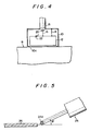
- the inventors made experiments to pick up the surface currents induced in the body by such broadcast waves by means of automobile antenna device as illustrated in Fig. 4.
- a generally rectangular loop antenna 12 is internally fixed in a casing 10 made of electrically conductive material to shield the loop antenna from unwanted external electromagnetic fields.
- a portion of this loop antenna 12 is exposed to the outside through an opening 10a which is provided in the casing 10 and this exposed portion is placed closely adjacent to the surface of the body B so that the magnetic flux produced by the surface current can be easily picked up by the loop antenna 12.
- Another part of the loop antenna 12 is connected to the casing 10 by a lead 14, and the output end 16 is connected to a center lead 20 of a coaxial cable 18.
- a capacitor 22 is connected to another part of the loop antenna 12 in order to increase the pick-up efficiency of the antenna by resonance of the frequency of the loop antenna 12 to the desired reception frequency.
- the magnetic flux created by the high frequency surface current which is induced by the broadcast waves is acquired by the loop antenna 12, and the casing 10 shields the antenna from unwanted external electromagnetic fields thereby enabling sensitive detection of the surface current induced in the automobile body by the broadcast waves.
- the detected signal obtained in this way is fed out through the coaxial cable 18 and supplied to the various receivers by way of voltage amplifiers, not illustrated.
- the loop antenna of the automobile antenna device is installed with one longer side 24a of a pick-up 24, similar to the loop antenna 12 shown in Fig. 4, closely adjacent to the marginal edge of a metal plate 26.
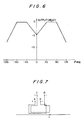
- Fig. 6 The measured result of this investigation is shown in Fig. 6. As is evident from this figure, the detection efficiency of the surface current is greatest in the ranges 45 to 90 degrees and -45 to -90 degrees in the angle ⁇ made between the plane of the loop of the pick-up probe 24 and the extended center line of the metal plate 26, and the detection efficiency is lower at any other angle.
- the loop antenna 12 can detect the surface current of the automobile body with high efficiency by arranging the plane of its loop at an angle in the range of 45 to 90 degrees or -45 to -90 degrees to the extended center line of the metal plate of the body.
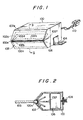
- An automobile antenna device in accordance with the present invention is based on the above described principles and findings, and an embodiment will be hereinafter described with reference to Figs. 1 and 2.
- Fig. 1 is a perspective illustration of an automobile antenna device in accordance with the present invention
- Fig. 2 is a sectional view taken on line II-II of Fig. 1.
- the automobile antenna device in Fig. 1 includes a loop antenna 102 which is internally fixed in a casing 100 of electrically conductive material to shield the loop antenna from unwanted external electromagnetic fields.
- the casing 100 has an elongate opening 100a to expose one longer side of each of a plurality of generally rectangular loops of the loop antenna 102.
- the longer sides of the loop antenna 102 exposed through the opening 100a extend lengthwise of and closely adjacent to a marginal edge portion of a metal plate of the automobile body, for example a roof rim member.
- the automobile antenna device is attached to the automobile body by the attachments 104 fixed to the casing 100 by bolts and nuts, spot welding or the like.
- the embodiment is characterized in that the loop antenna 102 is composed of five serially connected generally rectangular loops 102a, 102b, 102c, 102d, and 102e extending in a corresponding plurality of planes, the planes being disposed in sectorial array so that they intersect one another along a common line along the opening 100a and lie at uniform angles to one another about the common line.
- the sectorial array has an included angle at the common line of substantially 45° on each side of the centre line of plate 105.
- one loop at least among the loops 102a to 102e can be positioned at an efficient detection angle for the surface currents, that is, at 45 to 90 degrees or -45 to -90 degrees, as is shown in Fig. 6, and the surface currents can be detected with high efficiency, despite the casing being attached at any angle.
- the output voltage can theoretically be five times higher than that of an antenna with just one loop.
- the respective loops are sectorially arranged, the incidental capacitance between the respective loops is extremely small in comparison with that which arises in a simple densely packed winding.
- the practical problems of a shift of the resonant frequency and a decrease of acuteness (Q) and sensitivity caused by the shift do not occur.
- the metal plate 105 of the automobile body be inserted and arranged into the opening 100a to have the distance between the exposed longer sides of the loops of the loop antenna 102 and the metal plate 105 as short as possible. Consequently, the detection efficiency of the surface current is increased.
- the surface currents detected as described above are fed to a circuit 106 housed in the casing 100 by way of output terminals 102f and 102g of the loop antennas to be matched and amplified by circuit 106. Furthermore, the detected signal obtained in such a way is fed out by a coaxial cable not illustrated, by way of a connector 108 to be supplied to the various receivers through voltage amplifiers.
- the power source and a control signal source are connected and supplied to control the circuit 106 through a control signal wire 110.
- the automobile antenna device permits broadcast waves to be received with high efficiency and reliability without undue restriction of installing angles, and without externally exposing the automobile antenna device.
- the automobile antenna device can be installed closely adjacent the marginal edge portion of any part of the metal plate of the automobile body where the surface currents can be produced by broadcast waves, for example a roof rim member, engine hood, or trunk lid, and preferably where the surface current flows strongly.
Landscapes
- Engineering & Computer Science (AREA)
- Remote Sensing (AREA)
- Details Of Aerials (AREA)
- Input Circuits Of Receivers And Coupling Of Receivers And Audio Equipment (AREA)
- Support Of Aerials (AREA)
Priority Applications (1)
| Application Number | Priority Date | Filing Date | Title |
|---|---|---|---|
| AT85308573T ATE74472T1 (de) | 1984-11-27 | 1985-11-26 | Fahrzeugantennenvorrichtung. |
Applications Claiming Priority (2)
| Application Number | Priority Date | Filing Date | Title |
|---|---|---|---|
| JP251244/84 | 1984-11-27 | ||
| JP59251244A JPS61128609A (ja) | 1984-11-27 | 1984-11-27 | 自動車用アンテナ装置 |
Publications (3)
| Publication Number | Publication Date |
|---|---|
| EP0183522A2 EP0183522A2 (en) | 1986-06-04 |
| EP0183522A3 EP0183522A3 (en) | 1988-04-20 |
| EP0183522B1 true EP0183522B1 (en) | 1992-04-01 |
Family
ID=17219873
Family Applications (1)
| Application Number | Title | Priority Date | Filing Date |
|---|---|---|---|
| EP85308573A Expired - Lifetime EP0183522B1 (en) | 1984-11-27 | 1985-11-26 | Automobile antenna device |
Country Status (7)
| Country | Link |
|---|---|
| US (1) | US4679052A (da) |
| EP (1) | EP0183522B1 (da) |
| JP (1) | JPS61128609A (da) |
| AT (1) | ATE74472T1 (da) |
| CA (1) | CA1239694A (da) |
| DE (1) | DE3585775D1 (da) |
| DK (1) | DK545785A (da) |
Families Citing this family (4)
| Publication number | Priority date | Publication date | Assignee | Title |
|---|---|---|---|---|
| JPS61136304A (ja) * | 1984-12-06 | 1986-06-24 | Toyota Motor Corp | 自動車用アンテナ装置 |
| DE10107319A1 (de) * | 2000-02-18 | 2002-01-31 | Aisin Seiki | Rahmenantennenvorrichtung |
| JP4037703B2 (ja) * | 2002-06-28 | 2008-01-23 | 日本電気株式会社 | 内蔵アンテナ及び無線機 |
| US20120218068A1 (en) * | 2011-02-28 | 2012-08-30 | Equos Research Co., Ltd. | Antenna |
Family Cites Families (7)
| Publication number | Priority date | Publication date | Assignee | Title |
|---|---|---|---|---|
| CH226579A (de) * | 1942-01-28 | 1943-04-15 | E Herzer Alfred | Empfangsrahmen. |
| US2520986A (en) * | 1947-10-22 | 1950-09-05 | Motorola Inc | Vehicular antenna system |
| US3495264A (en) * | 1966-12-09 | 1970-02-10 | Continental Electronics Mfg | Loop antenna comprising plural helical coils on closed magnetic core |
| US3573830A (en) * | 1968-02-08 | 1971-04-06 | Sony Corp | Loop antenna |
| US3872455A (en) * | 1971-11-17 | 1975-03-18 | Monitron Ind | Physiological measurement display system |
| US3993998A (en) * | 1975-06-06 | 1976-11-23 | Kimmett James P | Directional loop antenna with plural dielectric coverings |
| FR2534692A1 (fr) * | 1982-10-15 | 1984-04-20 | Thomson Csf | Dispositif capteur de champ magnetique alternatif a haute sensibilite et a large bande, et appareil de mesure l'utilisant |
-
1984
- 1984-11-27 JP JP59251244A patent/JPS61128609A/ja active Pending
-
1985
- 1985-11-21 CA CA000495866A patent/CA1239694A/en not_active Expired
- 1985-11-26 AT AT85308573T patent/ATE74472T1/de not_active IP Right Cessation
- 1985-11-26 DK DK545785A patent/DK545785A/da not_active Application Discontinuation
- 1985-11-26 DE DE8585308573T patent/DE3585775D1/de not_active Expired - Lifetime
- 1985-11-26 EP EP85308573A patent/EP0183522B1/en not_active Expired - Lifetime
- 1985-11-26 US US06/801,771 patent/US4679052A/en not_active Expired - Fee Related
Also Published As
| Publication number | Publication date |
|---|---|
| EP0183522A2 (en) | 1986-06-04 |
| DE3585775D1 (de) | 1992-05-07 |
| US4679052A (en) | 1987-07-07 |
| DK545785A (da) | 1986-05-28 |
| DK545785D0 (da) | 1985-11-26 |
| JPS61128609A (ja) | 1986-06-16 |
| ATE74472T1 (de) | 1992-04-15 |
| EP0183522A3 (en) | 1988-04-20 |
| CA1239694A (en) | 1988-07-26 |
Similar Documents
| Publication | Publication Date | Title |
|---|---|---|
| EP0183523B1 (en) | Automobile antenna system | |
| EP0187446A1 (en) | Automobile antenna | |
| US4879570A (en) | Broadcasting wave reception antenna | |
| EP0181200A2 (en) | Automobile signal receiving apparatus | |
| US4811024A (en) | Automobile antenna | |
| EP0181765B1 (en) | Automobile antenna system | |
| EP0181120A2 (en) | Automobile antenna system | |
| US4717921A (en) | Automobile antenna system | |
| US4717920A (en) | Automobile antenna system | |
| EP0221694A2 (en) | Vehicle antenna system | |
| US4823141A (en) | Vehicle antenna system | |
| EP0183522B1 (en) | Automobile antenna device | |
| US4816837A (en) | Automobile antenna system | |
| EP0223398B1 (en) | Vehicle antenna system | |
| EP0180462B1 (en) | Automobile antenna system | |
| JPH0251083A (ja) | Gps受信用アンテナ | |
| EP0182614B1 (en) | Automobile antenna system | |
| US4792807A (en) | Automobile antenna system | |
| WO2006103820A1 (ja) | 車載用アンテナ | |
| EP0213743B1 (en) | Automobile antenna system | |
| US6115001A (en) | Antenna device | |
| CA1097756A (en) | Multiport cable choke |
Legal Events
| Date | Code | Title | Description |
|---|---|---|---|
| PUAI | Public reference made under article 153(3) epc to a published international application that has entered the european phase |
Free format text: ORIGINAL CODE: 0009012 |
|
| AK | Designated contracting states |
Kind code of ref document: A2 Designated state(s): AT CH DE FR GB LI SE |
|
| PUAL | Search report despatched |
Free format text: ORIGINAL CODE: 0009013 |
|
| AK | Designated contracting states |
Kind code of ref document: A3 Designated state(s): AT CH DE FR GB LI SE |
|
| 17P | Request for examination filed |
Effective date: 19880530 |
|
| 17Q | First examination report despatched |
Effective date: 19891017 |
|
| GRAA | (expected) grant |
Free format text: ORIGINAL CODE: 0009210 |
|
| AK | Designated contracting states |
Kind code of ref document: B1 Designated state(s): AT CH DE FR GB LI SE |
|
| REF | Corresponds to: |
Ref document number: 74472 Country of ref document: AT Date of ref document: 19920415 Kind code of ref document: T |
|
| ET | Fr: translation filed | ||
| REF | Corresponds to: |
Ref document number: 3585775 Country of ref document: DE Date of ref document: 19920507 |
|
| PLBE | No opposition filed within time limit |
Free format text: ORIGINAL CODE: 0009261 |
|
| STAA | Information on the status of an ep patent application or granted ep patent |
Free format text: STATUS: NO OPPOSITION FILED WITHIN TIME LIMIT |
|
| 26N | No opposition filed | ||
| PGFP | Annual fee paid to national office [announced via postgrant information from national office to epo] |
Ref country code: FR Payment date: 19941109 Year of fee payment: 10 |
|
| PGFP | Annual fee paid to national office [announced via postgrant information from national office to epo] |
Ref country code: AT Payment date: 19941111 Year of fee payment: 10 |
|
| PGFP | Annual fee paid to national office [announced via postgrant information from national office to epo] |
Ref country code: SE Payment date: 19941116 Year of fee payment: 10 Ref country code: GB Payment date: 19941116 Year of fee payment: 10 |
|
| PGFP | Annual fee paid to national office [announced via postgrant information from national office to epo] |
Ref country code: DE Payment date: 19941123 Year of fee payment: 10 Ref country code: CH Payment date: 19941123 Year of fee payment: 10 |
|
| EAL | Se: european patent in force in sweden |
Ref document number: 85308573.6 |
|
| PG25 | Lapsed in a contracting state [announced via postgrant information from national office to epo] |
Ref country code: GB Effective date: 19951126 Ref country code: AT Effective date: 19951126 |
|
| PG25 | Lapsed in a contracting state [announced via postgrant information from national office to epo] |
Ref country code: SE Effective date: 19951127 |
|
| PG25 | Lapsed in a contracting state [announced via postgrant information from national office to epo] |
Ref country code: LI Effective date: 19951130 Ref country code: CH Effective date: 19951130 |
|
| REG | Reference to a national code |
Ref country code: CH Ref legal event code: PL |
|
| GBPC | Gb: european patent ceased through non-payment of renewal fee |
Effective date: 19951126 |
|
| PG25 | Lapsed in a contracting state [announced via postgrant information from national office to epo] |
Ref country code: FR Effective date: 19960731 |
|
| PG25 | Lapsed in a contracting state [announced via postgrant information from national office to epo] |
Ref country code: DE Effective date: 19960801 |
|
| EUG | Se: european patent has lapsed |
Ref document number: 85308573.6 |
|
| REG | Reference to a national code |
Ref country code: FR Ref legal event code: ST |