EP0183452A2 - Opening roof for motor vehicles - Google Patents
Opening roof for motor vehicles Download PDFInfo
- Publication number
- EP0183452A2 EP0183452A2 EP85308343A EP85308343A EP0183452A2 EP 0183452 A2 EP0183452 A2 EP 0183452A2 EP 85308343 A EP85308343 A EP 85308343A EP 85308343 A EP85308343 A EP 85308343A EP 0183452 A2 EP0183452 A2 EP 0183452A2
- Authority
- EP
- European Patent Office
- Prior art keywords
- opening
- support member
- panel
- cam surface
- support
- Prior art date
- Legal status (The legal status is an assumption and is not a legal conclusion. Google has not performed a legal analysis and makes no representation as to the accuracy of the status listed.)
- Granted
Links
Images


Classifications
-
- B—PERFORMING OPERATIONS; TRANSPORTING
- B60—VEHICLES IN GENERAL
- B60J—WINDOWS, WINDSCREENS, NON-FIXED ROOFS, DOORS, OR SIMILAR DEVICES FOR VEHICLES; REMOVABLE EXTERNAL PROTECTIVE COVERINGS SPECIALLY ADAPTED FOR VEHICLES
- B60J7/00—Non-fixed roofs; Roofs with movable panels, e.g. rotary sunroofs
- B60J7/08—Non-fixed roofs; Roofs with movable panels, e.g. rotary sunroofs of non-sliding type, i.e. movable or removable roofs or panels, e.g. let-down tops or roofs capable of being easily detached or of assuming a collapsed or inoperative position
- B60J7/085—Non-fixed roofs; Roofs with movable panels, e.g. rotary sunroofs of non-sliding type, i.e. movable or removable roofs or panels, e.g. let-down tops or roofs capable of being easily detached or of assuming a collapsed or inoperative position winding up, e.g. for utility vehicles
-
- B—PERFORMING OPERATIONS; TRANSPORTING
- B60—VEHICLES IN GENERAL
- B60J—WINDOWS, WINDSCREENS, NON-FIXED ROOFS, DOORS, OR SIMILAR DEVICES FOR VEHICLES; REMOVABLE EXTERNAL PROTECTIVE COVERINGS SPECIALLY ADAPTED FOR VEHICLES
- B60J7/00—Non-fixed roofs; Roofs with movable panels, e.g. rotary sunroofs
- B60J7/02—Non-fixed roofs; Roofs with movable panels, e.g. rotary sunroofs of sliding type, e.g. comprising guide shoes
- B60J7/04—Non-fixed roofs; Roofs with movable panels, e.g. rotary sunroofs of sliding type, e.g. comprising guide shoes with rigid plate-like element or elements, e.g. open roofs with harmonica-type folding rigid panels
- B60J7/05—Non-fixed roofs; Roofs with movable panels, e.g. rotary sunroofs of sliding type, e.g. comprising guide shoes with rigid plate-like element or elements, e.g. open roofs with harmonica-type folding rigid panels pivoting upwardly to vent mode and moving downward before sliding to fully open mode
Definitions
- This invention relates to an opening roof assembly for a motor vehicle of the type having a rigid panel closing an opening in the vehicle roof and which can be opened by pivoting the panel upwardly about a transverse horizontal axis adjacent to its front edge so that the rear edge of the panel is above the vehicle roof.
- the panel is supported at each side on respective guide rails extending along each side of the opening in the vehicle roof.
- the invention can be applied to a roof of this type which can also be opened by sliding the panel rearwardly below the vehicle roof behind the opening.
- an opening roof assembly for a motor vehicle comprises a rigid panel adapted to close an opening in a vehicle roof, respective guide tracks arranged to be secured to the vehicle roof on each side of the opening below the level of the vehicle roof, and respective support means for each side of the panel, each support means comprising a first support member having thereon a cam surface of arcuate shape with its concave side upwards and its front end lower than its rear end, a second support member having cam follower means engaging with the cam surface, and coupling means for retaining the cam follower means in engagement with the cam surface, one of the support members being slidably mounted on the corresponding guide track and the other support member being secured to the underside of the panel, whereby relative movement between the two support members causes the first support member to pivot relative to the second support member to raise the rear edge of the panel.
- the arcuate shape is circular.
- the guide tracks extend below the vehicle roof behind the opening so that the roof can be opened in this way by simultaneous movement of the two support members along the track.
- the cam surface comprises one side of a flange and the coupling means comprises second cam follower means on the second support member adapted to engage with the other side of the flange.
- the first and second cam follower means may comprise at least two abutment members engaging with one side of the flange and at least one abutment member 'engaging with the other side of the flange.
- the first and second cam follower means may comprise respective side walls of an arcuate groove of the same radius as that of the cam surface.
- the cam surface comprises one wall of a slot in the first support member, the opposite wall of the slot forming the coupling means and the cam follower means comprising two spaced projections on the second support member engaging in the slot
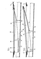
- Figure 1 shows the upper part of the body of a saloon motor car comprising a bonnet 10, a windscreen 12, a roof 1 4 , a rear window 16 and a boot 18.
- a movable glass roof panel 20 is located in a frame 22 bounding an opening in the vehicle roof.
- the frame 22 includes a drain tray 24 forming the bottom of a chamber into which the roof panel 20 can be slid below the vehicle roof 14.
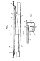
- Figures 2 and 3 show the track 26 on the car driver's right-hand side of the opening in the vehicle roof 14, in longitudinal cross-section.
- a guide shoe 28 is mounted in the track 26 and drive means (not shown) are provided for moving it along the track 26 in synchronism with the corresponding guide shoe in the track on the other side of the opening in the vehicle roof 14.
- a support member 30 is secured to the underside of the panel 20 so as to project downwardly, adjacent to the guide shoe 28.
- the support member 30 extends along substantially the whole of the corresponding side of the panel 20 and has a laterally projecting flange 32 on its bottom edge.
- the flange 32 is of part-cylindrical shape, the cylinder axis being located parallel to and above the front edge of the panel 20.
- a first pair of rollers 34, 36 is mounted on the guide shoe 28 near its front end.
- a second pair of rollers 38, 40 is mounted on the guide shoe 28 near its rear end.
- the lower rollers 34, 38 of each pair engage with the lower surface of the flange 32 and serve to support the panel 20.
- the upper rollers 36 and 40 engage with the upper sjrface of the flange 32, thus serving as -Quoting means to maintain the lower rollers 34 and 38 in engagement with the lower surface thereof.
- Figure 2 shows the rear edge of the panel 20 below the level of the vehicle roof 14.
- the shoe 28 is in its rearmost position relative to the support member 30, with the upper roller 4 0 abutting the underside of the panel 20. Rearward movement of the shoe 28 from this position causes the panel 20 to slide below the vehicle roof 14 behind the opening therein.
- Figures 6 and 7 illustrate an alternative embodiment of the invention in which the shoe 28 of Figures 2 to 5 is replaced by a shoe 50 having an arcuate slot 52 in the side wall facing the support member 30.
- the slot 52 is of the same radius as the flange 32, its upper wall replacing the upper rollers 36 and 40 and its lower wall replacing the lower rollers 34 and 38.
- FIGS 8 and 9 illustrate a further embodiment of the invention in which both the shoe and the support member differ from those described above.
- a support member 60 which is secured to the panel in the same position as the support member 30 of Figures 2 to 7, has an arcuate slot 62 therein of the same curvature as that of the flange 32.
- a shoe 64 which is slidably mounted in the track 26, carries front and rear pegs 66 and 68 which engage in the slot 62.
Landscapes
- Engineering & Computer Science (AREA)
- Mechanical Engineering (AREA)
- Body Structure For Vehicles (AREA)
- Vehicle Interior And Exterior Ornaments, Soundproofing, And Insulation (AREA)
- Automatic Cycles, And Cycles In General (AREA)
Abstract
Description
- This invention relates to an opening roof assembly for a motor vehicle of the type having a rigid panel closing an opening in the vehicle roof and which can be opened by pivoting the panel upwardly about a transverse horizontal axis adjacent to its front edge so that the rear edge of the panel is above the vehicle roof. The panel is supported at each side on respective guide rails extending along each side of the opening in the vehicle roof. The invention can be applied to a roof of this type which can also be opened by sliding the panel rearwardly below the vehicle roof behind the opening.
- According to the invention, an opening roof assembly for a motor vehicle comprises a rigid panel adapted to close an opening in a vehicle roof, respective guide tracks arranged to be secured to the vehicle roof on each side of the opening below the level of the vehicle roof, and respective support means for each side of the panel, each support means comprising a first support member having thereon a cam surface of arcuate shape with its concave side upwards and its front end lower than its rear end, a second support member having cam follower means engaging with the cam surface, and coupling means for retaining the cam follower means in engagement with the cam surface, one of the support members being slidably mounted on the corresponding guide track and the other support member being secured to the underside of the panel, whereby relative movement between the two support members causes the first support member to pivot relative to the second support member to raise the rear edge of the panel.
- Preferably, the arcuate shape is circular.
- When the invention is to be applied to a roof which can also be opened by sliding the panel rearwardly below the vehicle roof behind the opening, the guide tracks extend below the vehicle roof behind the opening so that the roof can be opened in this way by simultaneous movement of the two support members along the track.
- In one form of the invention, the cam surface comprises one side of a flange and the coupling means comprises second cam follower means on the second support member adapted to engage with the other side of the flange. The first and second cam follower means may comprise at least two abutment members engaging with one side of the flange and at least one abutment member 'engaging with the other side of the flange. Alternatively, if the arc forming the cam surface is circular, the first and second cam follower means may comprise respective side walls of an arcuate groove of the same radius as that of the cam surface.
- In another form of the invention, the cam surface comprises one wall of a slot in the first support member, the opposite wall of the slot forming the coupling means and the cam follower means comprising two spaced projections on the second support member engaging in the slot
- Embodiments of the invention will now be described, by way of example, with reference to the accompanying drawings, in which:
- Figure 1 is a fragmentary perspective sectional view of a motor car fitted with an opening roof assembly of the first kind to which the invention relates, showing the panel in its closed position and each of its two alternative open poitions;
- Figure 2 is a longitudinal sectional view of an opening roof assembly, of the kind shown in Figure 1, in accordance with a first embodiment of the invention, with the rear edge of the panel lowered prior to sliding below the vehicle roof;
- Figure 3 is a cross-sectional view taken on the line 3 - 3 in Figure 2;
- Figure 4 is a cross-sectional view, similar to Figure 2 but with the panel closed;
- Figure 5 is a cross-sectional view, similar to Figure 2 but with the rear edge of the panel raised;
- Figure 6 is a longitudinal sectional view, similar to Figure 2, of an opening roof assembly in accordance with a second embodiment of the invention;
- Figure 7 is a cross-sectional view taken on the line 7 - 7 in Figure 6;
- Figure 8 is a longitudinal sectional view, similar to Figure 2, of an opening roof assembly in accordance with a third embodiment of the invention; and
- Figure 9 is a cross-sectional view taken on the line 9 - 9 in Figure 8.
- Figure 1 shows the upper part of the body of a saloon motor car comprising a
bonnet 10, a windscreen 12, a roof 14, arear window 16 and aboot 18. A movableglass roof panel 20 is located in aframe 22 bounding an opening in the vehicle roof. Theframe 22 includes adrain tray 24 forming the bottom of a chamber into which theroof panel 20 can be slid below thevehicle roof 14. - A respective guide track, on which the
panel 20 is slidable, extends along each side of the opening in thevehicle roof 14 and into the space above thedrain tray 24. Figures 2 and 3 show thetrack 26 on the car driver's right-hand side of the opening in thevehicle roof 14, in longitudinal cross-section. Aguide shoe 28 is mounted in thetrack 26 and drive means (not shown) are provided for moving it along thetrack 26 in synchronism with the corresponding guide shoe in the track on the other side of the opening in thevehicle roof 14. - A
support member 30 is secured to the underside of thepanel 20 so as to project downwardly, adjacent to theguide shoe 28. Thesupport member 30 extends along substantially the whole of the corresponding side of thepanel 20 and has a laterally projectingflange 32 on its bottom edge. Theflange 32 is of part-cylindrical shape, the cylinder axis being located parallel to and above the front edge of thepanel 20. A first pair ofrollers guide shoe 28 near its front end. A second pair ofrollers guide shoe 28 near its rear end. Thelower rollers flange 32 and serve to support thepanel 20. Theupper rollers flange 32, thus serving as -Quoting means to maintain thelower rollers - Figure 2 shows the rear edge of the
panel 20 below the level of thevehicle roof 14. Theshoe 28 is in its rearmost position relative to thesupport member 30, with the upper roller 40 abutting the underside of thepanel 20. Rearward movement of theshoe 28 from this position causes thepanel 20 to slide below the vehicle roof 14 behind the opening therein. - If the
panel 20 is then returned to the position shown in Figure 2 by sliding theshoe 28 forwardly, aseal 42 on the front edge of thepanel 20 comes into abutment with the front edge of the roof opening, preventing further forward movement of thepanel 20 and thesupport member 30. Continued forward movement of theshoe 28 causes therollers flange 32, thereby raising the rear edge of thepanel 20 to the level of thevehicle roof 14 so as to close the opening therein, as shown in Figure 4. If forward movement of theshoe 28 continues, the rear edge of thepanel 20 is raised above the level of the vehicle roof, as shown in Figure 5. - Figures 6 and 7 illustrate an alternative embodiment of the invention in which the
shoe 28 of Figures 2 to 5 is replaced by ashoe 50 having anarcuate slot 52 in the side wall facing thesupport member 30. Theslot 52 is of the same radius as theflange 32, its upper wall replacing theupper rollers lower rollers - Figures 8 and 9 illustrate a further embodiment of the invention in which both the shoe and the support member differ from those described above. A support member 60, which is secured to the panel in the same position as the
support member 30 of Figures 2 to 7, has anarcuate slot 62 therein of the same curvature as that of theflange 32. Ashoe 64, which is slidably mounted in thetrack 26, carries front and rear pegs 66 and 68 which engage in theslot 62. - Both the embodiment of Figures 6 and 7 and the embodiment of Figures 8 and 9 operate in a similar manner to that described above with reference to Figures 2 to 5.
Claims (7)
Applications Claiming Priority (2)
| Application Number | Priority Date | Filing Date | Title |
|---|---|---|---|
| GB8430292 | 1984-11-30 | ||
| GB848430292A GB8430292D0 (en) | 1984-11-30 | 1984-11-30 | Opening roof for motor vehicles |
Publications (3)
| Publication Number | Publication Date |
|---|---|
| EP0183452A2 true EP0183452A2 (en) | 1986-06-04 |
| EP0183452A3 EP0183452A3 (en) | 1988-04-06 |
| EP0183452B1 EP0183452B1 (en) | 1990-02-07 |
Family
ID=10570510
Family Applications (1)
| Application Number | Title | Priority Date | Filing Date |
|---|---|---|---|
| EP85308343A Expired - Lifetime EP0183452B1 (en) | 1984-11-30 | 1985-11-15 | Opening roof for motor vehicles |
Country Status (6)
| Country | Link |
|---|---|
| US (1) | US4655500A (en) |
| EP (1) | EP0183452B1 (en) |
| JP (1) | JPS61132416A (en) |
| DE (1) | DE3575891D1 (en) |
| ES (1) | ES290534Y (en) |
| GB (1) | GB8430292D0 (en) |
Cited By (1)
| Publication number | Priority date | Publication date | Assignee | Title |
|---|---|---|---|---|
| EP0370250A2 (en) * | 1988-11-22 | 1990-05-30 | Gabel Gmbh | Swing-out roof part for motor vehicles |
Families Citing this family (2)
| Publication number | Priority date | Publication date | Assignee | Title |
|---|---|---|---|---|
| JPS61175121A (en) * | 1985-01-29 | 1986-08-06 | Oi Seisakusho Co Ltd | Sliding roof device for automobile |
| US7425033B2 (en) * | 2003-09-03 | 2008-09-16 | Intier Automotive Closures Inc. | Vehicle sunroof assembly |
Citations (2)
| Publication number | Priority date | Publication date | Assignee | Title |
|---|---|---|---|---|
| DE2648664A1 (en) * | 1976-10-27 | 1978-05-03 | Volkswagenwerk Ag | CLADDING FOR A VEHICLE SUNROOF WITH EXTENDING FUNCTION |
| DE3205445A1 (en) * | 1982-02-16 | 1983-08-25 | Fa. Wilhelm Schade, 5970 Plettenberg | Vehicle roof with a tilt and slide cover arranged in the area of a roof opening |
Family Cites Families (3)
| Publication number | Priority date | Publication date | Assignee | Title |
|---|---|---|---|---|
| US28346A (en) * | 1860-05-22 | Flush bolt | ||
| DE3045364C2 (en) * | 1980-12-02 | 1982-10-14 | Karosseriewerke Weinsberg Gmbh, 7102 Weinsberg | Lifting device for a vehicle roof |
| US4403805A (en) * | 1982-01-06 | 1983-09-13 | General Motors Corporation | Sliding sunroof with power operated ventilator |
-
1984
- 1984-11-30 GB GB848430292A patent/GB8430292D0/en active Pending
-
1985
- 1985-11-05 US US06/795,095 patent/US4655500A/en not_active Expired - Fee Related
- 1985-11-15 DE DE8585308343T patent/DE3575891D1/en not_active Expired - Lifetime
- 1985-11-15 EP EP85308343A patent/EP0183452B1/en not_active Expired - Lifetime
- 1985-11-26 ES ES1985290534U patent/ES290534Y/en not_active Expired
- 1985-11-30 JP JP60270579A patent/JPS61132416A/en active Pending
Patent Citations (2)
| Publication number | Priority date | Publication date | Assignee | Title |
|---|---|---|---|---|
| DE2648664A1 (en) * | 1976-10-27 | 1978-05-03 | Volkswagenwerk Ag | CLADDING FOR A VEHICLE SUNROOF WITH EXTENDING FUNCTION |
| DE3205445A1 (en) * | 1982-02-16 | 1983-08-25 | Fa. Wilhelm Schade, 5970 Plettenberg | Vehicle roof with a tilt and slide cover arranged in the area of a roof opening |
Cited By (2)
| Publication number | Priority date | Publication date | Assignee | Title |
|---|---|---|---|---|
| EP0370250A2 (en) * | 1988-11-22 | 1990-05-30 | Gabel Gmbh | Swing-out roof part for motor vehicles |
| EP0370250A3 (en) * | 1988-11-22 | 1990-10-03 | Gabel Gmbh | Swing-out roof part for motor vehicles |
Also Published As
| Publication number | Publication date |
|---|---|
| ES290534U (en) | 1986-04-01 |
| JPS61132416A (en) | 1986-06-19 |
| ES290534Y (en) | 1986-11-16 |
| DE3575891D1 (en) | 1990-03-15 |
| US4655500A (en) | 1987-04-07 |
| GB8430292D0 (en) | 1985-01-09 |
| EP0183452A3 (en) | 1988-04-06 |
| EP0183452B1 (en) | 1990-02-07 |
Similar Documents
| Publication | Publication Date | Title |
|---|---|---|
| EP0194804B1 (en) | Opening roof for a motor vehicle | |
| US7810879B2 (en) | Vehicle sun roof system | |
| EP1070614B1 (en) | Open roof construction for a vehicle | |
| EP0143589B1 (en) | Opening roof for a motor vehicle | |
| US5845959A (en) | Slide tilt roof apparatus | |
| GB2161439A (en) | Vehicle roofs | |
| US7591500B2 (en) | Motor vehicle comprising a fully opening roof part | |
| US5046779A (en) | Sunroof structure for automotive vehicle | |
| EP1314599A1 (en) | Vehicle | |
| EP1070616B1 (en) | Open roof construction for a vehicle | |
| US5358303A (en) | Roof panel for a motor vehicle | |
| EP0183452A2 (en) | Opening roof for motor vehicles | |
| EP1084881A1 (en) | Open roof construction for a vehicle | |
| NL9200165A (en) | SPOILER ROOF. | |
| EP0244110A2 (en) | Opening roof for a motor vehicle | |
| CA1326693C (en) | Sliding-lifting roof for an automobile | |
| EP1331119A1 (en) | Vehicle with sliding and venting sunroof | |
| EP0106611B1 (en) | Sliding roof for motor vehicles | |
| EP0369680B1 (en) | Window regulator mechanism with kick-out feature | |
| EP0521589A2 (en) | Opening roof for a motor vehicle | |
| EP0106610B1 (en) | Sliding roof for motor vehicles | |
| JP3000636B2 (en) | Car sunroof structure | |
| JPH0139220Y2 (en) | ||
| JP2597086Y2 (en) | Drain channel interlocking device for vehicle sunroof | |
| GB2209795A (en) | Opening roof for motor vehicle |
Legal Events
| Date | Code | Title | Description |
|---|---|---|---|
| PUAI | Public reference made under article 153(3) epc to a published international application that has entered the european phase |
Free format text: ORIGINAL CODE: 0009012 |
|
| AK | Designated contracting states |
Kind code of ref document: A2 Designated state(s): DE FR GB IT |
|
| PUAL | Search report despatched |
Free format text: ORIGINAL CODE: 0009013 |
|
| AK | Designated contracting states |
Kind code of ref document: A3 Designated state(s): DE FR GB IT |
|
| 17P | Request for examination filed |
Effective date: 19880318 |
|
| 17Q | First examination report despatched |
Effective date: 19881229 |
|
| GRAA | (expected) grant |
Free format text: ORIGINAL CODE: 0009210 |
|
| AK | Designated contracting states |
Kind code of ref document: B1 Designated state(s): DE FR GB |
|
| REF | Corresponds to: |
Ref document number: 3575891 Country of ref document: DE Date of ref document: 19900315 |
|
| ET | Fr: translation filed | ||
| PGFP | Annual fee paid to national office [announced via postgrant information from national office to epo] |
Ref country code: FR Payment date: 19901114 Year of fee payment: 6 |
|
| PLBE | No opposition filed within time limit |
Free format text: ORIGINAL CODE: 0009261 |
|
| STAA | Information on the status of an ep patent application or granted ep patent |
Free format text: STATUS: NO OPPOSITION FILED WITHIN TIME LIMIT |
|
| 26N | No opposition filed | ||
| PG25 | Lapsed in a contracting state [announced via postgrant information from national office to epo] |
Ref country code: FR Effective date: 19920731 |
|
| REG | Reference to a national code |
Ref country code: FR Ref legal event code: ST |
|
| PGFP | Annual fee paid to national office [announced via postgrant information from national office to epo] |
Ref country code: DE Payment date: 19921123 Year of fee payment: 8 |
|
| PG25 | Lapsed in a contracting state [announced via postgrant information from national office to epo] |
Ref country code: DE Effective date: 19931001 |
|
| PGFP | Annual fee paid to national office [announced via postgrant information from national office to epo] |
Ref country code: GB Payment date: 19931108 Year of fee payment: 9 |
|
| PG25 | Lapsed in a contracting state [announced via postgrant information from national office to epo] |
Ref country code: GB Effective date: 19941115 |
|
| GBPC | Gb: european patent ceased through non-payment of renewal fee |
Effective date: 19941115 |