EP0183359A2 - Impact attenuating body - Google Patents
Impact attenuating body Download PDFInfo
- Publication number
- EP0183359A2 EP0183359A2 EP85307179A EP85307179A EP0183359A2 EP 0183359 A2 EP0183359 A2 EP 0183359A2 EP 85307179 A EP85307179 A EP 85307179A EP 85307179 A EP85307179 A EP 85307179A EP 0183359 A2 EP0183359 A2 EP 0183359A2
- Authority
- EP
- European Patent Office
- Prior art keywords
- impact attenuating
- cells
- impact
- attenuating body
- compartments
- Prior art date
- Legal status (The legal status is an assumption and is not a legal conclusion. Google has not performed a legal analysis and makes no representation as to the accuracy of the status listed.)
- Granted
Links
Images

Classifications
-
- E—FIXED CONSTRUCTIONS
- E01—CONSTRUCTION OF ROADS, RAILWAYS, OR BRIDGES
- E01F—ADDITIONAL WORK, SUCH AS EQUIPPING ROADS OR THE CONSTRUCTION OF PLATFORMS, HELICOPTER LANDING STAGES, SIGNS, SNOW FENCES, OR THE LIKE
- E01F15/00—Safety arrangements for slowing, redirecting or stopping errant vehicles, e.g. guard posts or bollards; Arrangements for reducing damage to roadside structures due to vehicular impact
- E01F15/14—Safety arrangements for slowing, redirecting or stopping errant vehicles, e.g. guard posts or bollards; Arrangements for reducing damage to roadside structures due to vehicular impact specially adapted for local protection, e.g. for bridge piers, for traffic islands
- E01F15/145—Means for vehicle stopping using impact energy absorbers
- E01F15/148—Means for vehicle stopping using impact energy absorbers mobile arrangements
-
- B—PERFORMING OPERATIONS; TRANSPORTING
- B60—VEHICLES IN GENERAL
- B60R—VEHICLES, VEHICLE FITTINGS, OR VEHICLE PARTS, NOT OTHERWISE PROVIDED FOR
- B60R19/00—Wheel guards; Radiator guards, e.g. grilles; Obstruction removers; Fittings damping bouncing force in collisions
-
- B—PERFORMING OPERATIONS; TRANSPORTING
- B60—VEHICLES IN GENERAL
- B60R—VEHICLES, VEHICLE FITTINGS, OR VEHICLE PARTS, NOT OTHERWISE PROVIDED FOR
- B60R19/00—Wheel guards; Radiator guards, e.g. grilles; Obstruction removers; Fittings damping bouncing force in collisions
- B60R2019/005—Crash attenuators, i.e. means added to highway service vehicles for softening high speed impacts
Landscapes
- Engineering & Computer Science (AREA)
- Mechanical Engineering (AREA)
- Architecture (AREA)
- Civil Engineering (AREA)
- Structural Engineering (AREA)
- Body Structure For Vehicles (AREA)
- Vibration Dampers (AREA)
Abstract

Description
- The present invention relates to impact attenuating bodies and more particularly to such impact attenuating bodies employed in applications contemplated for engagement by vehicles or other objects moving in a generally predetermined travel direction.
- Impact attenuating bodies of the type referred to above have commonly been employed in the prior art in a number of different applications. For example, they are commonly employed in connection with maintenance and surveillance vehicles used, for example, in transit areas such as highways, freeways and bridges. In such situations, even though the vehicles are highly visible and are provided with extra warning lights or other devices, they are commonly subject to collission or impact by overtaking vehicles.
- Customary protective devices such as bumpers and the like do not provide sufficient protection for the maintenance vehicles in such situations. At the same time, the overtaking vehicles may also be subject to substantial damage. Impact attenuating bodies have been developed for use in such maintenance vehicles in order to provide greater protection for the vehicles and their occupants during collisions.
- Generally impact attenuating bodies are elongated and are mounted, for example, on the rear of the maintenance vehicles so that an overtaking vehicle impacts the body instead of the truck. Shock absorbing material within the body not only protects the truck and its occupants during the collision but also tends to provide protection for occupants of the overtaking vehicle. In particular, it is desirable for such impact attenuating bodies to be able to gradually arrest movement of the vehicle over a selected distance of travel, for example, along one dimension of the impact body. After initial engagement of the overtaking vehicle with the body and during the selected distance of travel thereafter, the impact attenuating body is designed to dissipate the impact energy of the vehicle.
- A number of such impact attenuating bodies have been provided in the prior art as indicated, for example, in U.S. Patenty 3,907,353 issued September 23,1975 to Dinitz and U.S. Patent 4,008,915 issued February 22, 1977 to Walker. These references are typical of prior art impact attenuating bodies in that they employ a plurality of similarly formed and oriented elements or cells filled with shock absorbing material in order to accomplish the purposes referred to above.
- However, because of the generally substantial impact forces developed during such collisions, there has been found to remain an increasing demand for even more effective impact attenuating bodies.
- This invention provides an impact attenuating body adapted to be engaged by vehicles or other objects moving in generally a selected direction of travel, the impact attenuating body being further adapted for gradually arresting motion of the moving object and dissipating its impact energy, comprising frame means being collapsible along the travel direction and forming multiple rows of vertically arranged cells, said rows of cells being formed in transverse relation to the travel direction, said cells in each row providing differing effective degrees of shock absorption whereby movement of the object is arrested as it travels a selected distance after initial engagement with the body, said arrangement and cross-sectional shape of said cells causing the object to continue along substantially the same travel direction after its initial engagement with the body and while the impact energy of the object is being dissipated by the body.
- In a preferred construction of the present invention, an impact attenuating body is formed with multiple rows of vertically arranged compartments, with selected compartments spaced laterally apart from each other in transverse relation to the travel direction being generally void, intermediate compartments between the void compartments containing shock absorbing material selected for arresting movement of vehicles or other objects impacting the body.
- More preferably, the above impact attenuating bodv is formed with each void compartment and more preferably all of said compartments having a cross-sectional dimension parallel with the travel direction substantially greater than its width extending transverse to the travel direction. This configuration of the compartments, particularly the void compartments, serves in particular to assure that the vehicle or body continues to travel along the same travel direction after initial engagement with the body.
- The following is a description of some specific embodiments of the present invention
- having references to the accompanying drawings.in which:
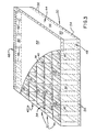
- Fig. 1 is a side view in elevation of an impact attenuating body constructed according to the present invention mounted on the back of a maintenance truck or the like.
- Fig. 2 is a rear view of Fig. 1.
- Fig. 3 is a perspective view with portions being broken away, of a collapsible frame assembly for an impact attenuating body according to the present invention.
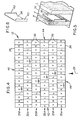
- Fig. 4 is a schematic illustration of preferred configurations for compartments within the impact attenuating body and a preferred arrangement of difference shock absorbing densities for said compartment.
- Fig. 5 is a fragmentary perspective view of a single void compartment within the impact attenuating body and compartments of different density shock absorbing materials on opposite sides thereof.
- Fig. 6 is an enlarged fragmentary view of one of a large number of brackets interconnected between laterally extending members for forming the compartments in the impact attenuating body.
- Referring now to the drawings and particularly to Figs. 1 and 2, an impact attenuating body of the type contemplated by the present invention is generally indicated at 12 for use with a maintenance truck or the like generally indicated at 14.
- Since most collisions of the type contemplated by the present invention involve vehicles or objects approaching the
maintenance truck 14 from the rear, theimpact attenuating body 12 is preferably mounted to extend rearwardly from the truck so that it will first be engaged by an overtaking vehicle. - As illustrated in Figs. 1 and 2, the
impact attenuating body 12 may be connected by hinges as indicated at 16 tostructural elements 18 of thetruck 14. Theimpact attenuating body 12 may be further interconnected with the truck, for example by means of lines orcables 20. Thecables 20 may further comprise adjusting means (not shown) for raising the impact attenuating body as generally indicated in phantom at 12'. The impact attenuating body may be raised into the position 12' for example when thetruck 14 is moving between different sites and is not subject to collision from overtaking vehicles as contemplated by the present invention. - The
impact attenuating body 12 may be provided with lights or signals means 22 and 24 visible when the impact attenuating body is in either its operating position shown in solid lines in Fig. 1 or in the transport position illustrated at 12'. Similarly, the impact attenuating body may be provided withadjustable rollers 26 or the like to facilitate handling and movement of the impact attenuating body when it is not mounted upon thetruck 14. However, these components are not particularly contemplated as being within the scope of the present invention. - Continuing with momentary reference to Fig. 1, the
impact attenuating body 12 is particularly contemplated for providing protection to thetruck 14 and also to an overtaking vehicle or other object commonly anticipated to travel along a direction generally indicated at 28. The manner in which theimpact attenuating body 12 accomplishes this object of the invention is described in greater detail below with reference to Figs. 3-6. - Referring to Figs. 3 and 4, the
impact attenuating body 12 is formed with acollapsible frame assembly 30 forming multiplelateral rows 32 ofcompartments 34. Thecompartments 34 contain different effective densities of shock absorbing material for purposes described in greater detail below. Referring particularly to Fig. 4 a large number of the compartments generally indicate a V are void. Of the remaining compartments, a portion of the indicated at H are filled with relatively high density shock absorbing material. The remaining compartments indicated at L are filled with relatively low density shock absorbing material. The corresponding effective shock absorbing values for the compartments V, H and L are generally proportional to their densities. - Note that the direction of travel contemplated for a vehicle or object impacting the
body 12 is also indicated at 28 in Fig. 4. Referring in combination to Figs. 3 and 4, all of the compartments, particularly the void compartments V, are formed with a cross-sectional dimension parallel to thetravel direction 28 substantially greater than their laterally extending dimension. - In a typical configuration disclosed here only for purposes of example, the
impact attenuating body 12 may be formed with each of the compartments V, H and L having a vertical length of about two feet. The elongated dimension of each compartment parallel to thetravel direction 28 is about one foot. The width of the void compartments may be in the range of 7 to 8 inches while the lateral dimension of both the high density and the low density compartments H and L is about 4 inches. Referring particularly to Fig. 4, it may be seen that different numbers of compartments are formed in alternatinglateral rows - One of the void compartments V is also illustrated in Fig. 5 with a high density compartment H on its left side and a low density compartment on its right side. Preferably, the high density compartments contain expanded rigid plastic foam having an effective shock absorbing density for example of about 2.5 pounds per cubic foot. The low density compartments L similarly contain expanded rigid plastic foam having a density for example of 1.7 pounds per cubic foot. Here again, these values are set forth by way of illustration and are not intended to be limiting in connection with the present invention.
- Before describing the
collapsible frame assembly 30, it is further noted with particular reference to Fig. 4 that each of thelateral rows - The arrangement of high density and low density compartments H and L is selected for providing a predetermined overall shock absorbing value for the
entire body 12 capable of arresting movement of vehicles or objects traveling along thedirection 28. Motion of the vehicle traveling within the national speed limit is preferably arrested after traveling a distance generally corresponding to a little less than the longitudinal dimension of the impact attenuating body parallel to thetravel direction 28. In this manner, impact forces within the overtaking vehicle are minimized while assuring protection for the truck 24 (see Figs. land 2). - The alternating arrangement of the void compartments V in each of the
lateral rows 32 and along the longitudinal dimension of thebody 12 serve to better assure that the vehicle or other object will continue traveling in substantially the same direction as indicated at 28 after initial impact with thebody 12. This object is accomplished because of the elongated configurations and arrangement of the compartments, particularly the void compartments V as best seen in Fig. 4. - Continuing with reference to Fig. 4, it may be seen that, because of the offset arrangement of
lateral rows 32 and the different numbers of compartments formed in each row, an increased number of low density compartments L is formed generally through a longitudinally central portion of the body parallel with thetravel direction 28. - In
alternating rows 32A, the arrangement of compartments between the void compartments V alternates between a high density compartment H and a low density compartment L. However, in the alternatelateral rows 32B, each centrally arranged void compartment V sub C has low density compartments L on each side thereof. The arrangement of low density compartments through the center of the body further serves to assure the continued travel of an overtaking vehicle or other body along the same direction oftravel 28 after it comes into impacting engagement with thebody 12. - Referring particularly to Fig. 3, the
collapsible frame assembly 30 is formed by a plurality of laterally extendingmembers 36 extending transversely across the attenuatingbody 12. Thelateral members 36 have a vertical dimension generally the same as the vertical lengths of thecompartments 34.Brackets 38 are interconnected in spaced apart relation between thelateral members 36 in order to form thecompartments 34 as are also illustrated in Fig. 4. Thebrackets 38 preferably have a vertical dimension about half that of thelateral members 36. Referring particularly to Fig. 6, the longitudinal ends of thebrackets 38 are formed withflanges 40 to facilitate their attachment to themembers 36. With thelateral members 36 and thebrackets 38 being formed from metal of sheet steel, the brackets are preferably interconnected between the lateral members by spot welding of theflanges 40 to the lateral members. - Continuing with reference to Fig. 3, a shell encompassing the
lateral sides integral sheet 50 of metal or the like. 'Preferably, opposite ends of thesheet 50 are substantially overlapped along the forwardlongitudinal end 46. Top and bottomflexible panels sheet 50 for example byrivets 56 in order to entirely close theimpact attenuating body 12. - In order to facilitate the attachment of the
impact attenuating body 12 to a vehicle such as thetruck 14 of Figs. 1 and 2, a mounting assembly is arranged on the forwardlongitudinal end 46. The mounting assembly is generally indicated at 58 and includes an additional sheet formed for example from plywood as indicated at 60 (Fig. 3) spanning the forwardlongitudinal end 46 of the impact attenuating body. Framed angle iron is attached to thesheet 50 and the plywood panel 60 at the forward longitudinal end of thebody 12. The framed angle iron is generally indicated at 62 and provides a means for attachment to the hinges 16 (see Figs. 1 and 2). - For purposes of illustration and not to limit the scope of the present invention, various components of the
collapsible frame assembly 30, in addition to those specified above, are formed from galvanized sheet steel or the like. For example, the shell orouter sheet 50 is formed from 18 gauge galvanized sheet steel. The cell dividers orlateral members 36 are formed from 20 gauge galvanized sheet steel while thebrackets 38 are formed from 22 gauge galvanized sheet steel. In the mountingassembly 58, the framing angle iron has a thickness of 1/8 inch and a width along its angled sides of 1-1/2 inch. The plywood panel 60 is 5/8 inch thick with the top andbottom panels - There has thus been described an embodiment of an impact attenuating body for providing improved protection for maintenance trucks and other vehicles as well as being useful in other related applications. Various modifications and additions will be apparent in addition to those specifically set forth above. Accordingly, the scope of the present invention is defined only by the following appended claims.
Claims (13)
Applications Claiming Priority (2)
| Application Number | Priority Date | Filing Date | Title |
|---|---|---|---|
| US665721 | 1984-10-29 | ||
| US06/665,721 US4635981A (en) | 1984-10-29 | 1984-10-29 | Impact attenuating body |
Publications (3)
| Publication Number | Publication Date |
|---|---|
| EP0183359A2 true EP0183359A2 (en) | 1986-06-04 |
| EP0183359A3 EP0183359A3 (en) | 1987-05-20 |
| EP0183359B1 EP0183359B1 (en) | 1990-05-30 |
Family
ID=24671312
Family Applications (1)
| Application Number | Title | Priority Date | Filing Date |
|---|---|---|---|
| EP85307179A Expired - Lifetime EP0183359B1 (en) | 1984-10-29 | 1985-10-08 | Impact attenuating body |
Country Status (6)
| Country | Link |
|---|---|
| US (1) | US4635981A (en) |
| EP (1) | EP0183359B1 (en) |
| JP (1) | JPS61113536A (en) |
| AU (1) | AU581689B2 (en) |
| CA (1) | CA1240345A (en) |
| DE (1) | DE3577983D1 (en) |
Cited By (1)
| Publication number | Priority date | Publication date | Assignee | Title |
|---|---|---|---|---|
| FR2602191A1 (en) * | 1986-08-04 | 1988-02-05 | Rafini Jean Pierre | Safety and signalling device for movable lorry tailgates |
Families Citing this family (81)
| Publication number | Priority date | Publication date | Assignee | Title |
|---|---|---|---|---|
| US4770420A (en) * | 1985-01-14 | 1988-09-13 | United Research And Manufacturing, Inc. | Vehicle mounting system for impact absorption apparatus |
| US4658941A (en) * | 1985-01-14 | 1987-04-21 | Hexcel Corporation | Vehicle mounting system for impact absorption apparatus |
| JPS61196846A (en) * | 1985-02-27 | 1986-09-01 | Showa Aircraft Ind Co Ltd | Rear-end collision accident preventive device of vehicle |
| US4711481A (en) * | 1985-10-25 | 1987-12-08 | Energy Absorption Systems, Inc. | Vehicle impact attenuating device |
| NL8503352A (en) * | 1985-12-05 | 1987-07-01 | Stamicarbon | BUMPER. |
| JPS6389445U (en) * | 1986-12-02 | 1988-06-10 | ||
| JPH0544204Y2 (en) * | 1987-07-08 | 1993-11-09 | ||
| US4928928A (en) * | 1988-01-12 | 1990-05-29 | The Texas A&M University System | Guardrail extruder terminal |
| US5052732A (en) * | 1990-04-02 | 1991-10-01 | Renco Supply, Inc. | Crash attenuator utilizing fibrous honeycomb material |
| US5199755A (en) * | 1991-04-03 | 1993-04-06 | Energy Absorption Systems, Inc. | Vehicle impact attenuating device |
| US5192157A (en) | 1991-06-05 | 1993-03-09 | Energy Absorption Systems, Inc. | Vehicle crash barrier |
| US5248129A (en) * | 1992-08-12 | 1993-09-28 | Energy Absorption Systems, Inc. | Energy absorbing roadside crash barrier |
| US6220575B1 (en) | 1995-01-18 | 2001-04-24 | Trn Business Trust | Anchor assembly for highway guardrail end terminal |
| US5700545A (en) | 1995-05-31 | 1997-12-23 | The Oakwood Group | Energy absorbing structure |
| US5697657A (en) * | 1996-01-11 | 1997-12-16 | Albert W. Unrath, Inc. | Vehicle mounted crash attenuation system |
| US5934737A (en) * | 1996-04-15 | 1999-08-10 | Chrysler Corporation | Dynamic impact energy absorbing assembly |
| US5947452A (en) * | 1996-06-10 | 1999-09-07 | Exodyne Technologies, Inc. | Energy absorbing crash cushion |
| US5746419A (en) * | 1996-10-16 | 1998-05-05 | General Motors Corporation | Energy absorbing device |
| US5927896A (en) | 1996-12-13 | 1999-07-27 | Gertz; David C. | Inertial barrier module |
| US6293727B1 (en) | 1997-06-05 | 2001-09-25 | Exodyne Technologies, Inc. | Energy absorbing system for fixed roadside hazards |
| US5957435A (en) * | 1997-07-11 | 1999-09-28 | Trn Business Trust | Energy-absorbing guardrail end terminal and method |
| US6129342A (en) * | 1997-07-11 | 2000-10-10 | Trn Business Trust | Guardrail end terminal for side or front impact and method |
| US6343821B2 (en) | 1997-11-24 | 2002-02-05 | Automotive Technologies International, Inc. | Damped crash attenuator |
| US6523872B2 (en) | 1997-11-24 | 2003-02-25 | Automotive Technologies International, Inc. | Damped crash attenuator |
| US6203079B1 (en) | 1997-11-24 | 2001-03-20 | Automotive Technologies International, Inc. | Damped crash attenuator |
| US7360822B2 (en) * | 1998-02-04 | 2008-04-22 | Oakwood Energy Management, Inc. | Modular energy absorber and method for configuring same |
| US6679967B1 (en) | 1998-02-04 | 2004-01-20 | Oakwood Energy Management, Inc. | Method for making a modular energy-absorbing assembly |
| US6017084A (en) * | 1998-02-04 | 2000-01-25 | Oakwood Energy Management Inc. | Energy absorbing assembly |
| US6682128B2 (en) | 1998-02-04 | 2004-01-27 | Oakwood Energy Management, Inc. | Composite energy absorber |
| US6199942B1 (en) | 1998-02-04 | 2001-03-13 | Oakwood Energy Management, Inc. | Modular energy absorbing assembly |
| US6062632A (en) * | 1998-03-20 | 2000-05-16 | Solectria Corporation | Vehicle body collision energy absorption system |
| US6092959A (en) * | 1998-11-16 | 2000-07-25 | Energy Absorption Systems, Inc. | Method for decelerating a vehicle, highway crash cushion, and energy absorbing element therefor |
| US7101111B2 (en) * | 1999-07-19 | 2006-09-05 | Exodyne Technologies Inc. | Flared energy absorbing system and method |
| US7306397B2 (en) * | 2002-07-22 | 2007-12-11 | Exodyne Technologies, Inc. | Energy attenuating safety system |
| US6835024B1 (en) | 2000-01-10 | 2004-12-28 | Traffix Devices, Inc. | Inertial barrier module array and methods |
| US7175361B1 (en) | 2000-01-10 | 2007-02-13 | Traffix Devices, Inc. | Inertial barrier module array and methods |
| US6491470B1 (en) | 2000-01-10 | 2002-12-10 | Traffix Devices, Inc. | Inertial barrier module |
| DE10005223C1 (en) * | 2000-02-05 | 2001-08-23 | Michael Rossmann | Device for the mechanical coupling of mutual movement dependencies of a crash cushion and a barrier panel |
| AU754339B2 (en) * | 2000-02-24 | 2002-11-14 | Evans Deakin Pty Limited | Energy absorbing apparatus |
| US6244637B1 (en) | 2000-03-02 | 2001-06-12 | Energy Absorption Systems, Inc. | Adjustable tailgate mount for truck mounted attenuator |
| SE522192C2 (en) * | 2000-05-17 | 2004-01-20 | Vaegverket Produktion | Anti-theft device for vehicles and method |
| US6461076B1 (en) | 2001-01-03 | 2002-10-08 | Energy Absorption Systems, Inc. | Vehicle impact attenuator |
| US20030077119A1 (en) * | 2001-09-28 | 2003-04-24 | Energy Absorption System, Inc. | Vehicle mounted crash attenuator |
| US6773201B2 (en) * | 2001-11-20 | 2004-08-10 | Safety Systems, Inc. | Soft wall for race tracks |
| FR2833055B1 (en) * | 2001-12-05 | 2004-07-02 | Peugeot Citroen Automobiles Sa | MECHANICAL DEVICE WITH CROSS SPRINGS, AND APPLICATION TO KINETIC ENERGY ABSORPTION |
| US6579034B1 (en) | 2001-12-19 | 2003-06-17 | Energy Absorption Systems, Inc. | Highway crash attenuator frame |
| US6863467B2 (en) * | 2002-02-27 | 2005-03-08 | Energy Absorption Systems, Inc. | Crash cushion with deflector skin |
| US20040025451A1 (en) * | 2002-08-05 | 2004-02-12 | Douglas Barton | Energy absorbing wall system and method of use |
| SE525249C2 (en) * | 2002-12-20 | 2005-01-11 | Vaegverket | Anti-theft device for vehicles |
| US20060193688A1 (en) * | 2003-03-05 | 2006-08-31 | Albritton James R | Flared Energy Absorbing System and Method |
| US7494165B2 (en) * | 2003-07-03 | 2009-02-24 | Netshape Energy Management Llc | Method of making bumper system using thermoformed component |
| US20050097004A1 (en) * | 2003-10-29 | 2005-05-05 | Eduardo Masse Blume | Method of advertising and related products |
| US7228723B2 (en) * | 2004-07-01 | 2007-06-12 | Netshape Energy Management Llc | Bumper impact-testing device |
| EP1614810B1 (en) * | 2004-07-06 | 2010-07-28 | Triopan Dähler AG | Impact attenuation device |
| US7874572B2 (en) * | 2005-01-10 | 2011-01-25 | Energy Absorption Systems, Inc. | Towable impact attenuator |
| EP1695874A1 (en) * | 2005-02-25 | 2006-08-30 | Albert W. Unrath, Inc. | Cushion for crash attenuation system |
| JP4743774B2 (en) * | 2006-06-07 | 2011-08-10 | イワブチ株式会社 | Clamp-type cable detention method and its equipment |
| DK2115221T3 (en) * | 2007-01-30 | 2015-12-21 | Traffix Devices Inc | Trailer mounted collision front |
| US7441817B1 (en) | 2007-04-23 | 2008-10-28 | Tma Acquisition, Llc | Trailer mounted crash attenuation system |
| US7533912B2 (en) * | 2007-06-12 | 2009-05-19 | Ford Global Technologies, Llc | Hybrid energy absorber for automobile bumper |
| US8726424B2 (en) | 2010-06-03 | 2014-05-20 | Intellectual Property Holdings, Llc | Energy management structure |
| US8974142B2 (en) | 2010-11-15 | 2015-03-10 | Energy Absorption Systems, Inc. | Crash cushion |
| US9516910B2 (en) | 2011-07-01 | 2016-12-13 | Intellectual Property Holdings, Llc | Helmet impact liner system |
| USD679058S1 (en) | 2011-07-01 | 2013-03-26 | Intellectual Property Holdings, Llc | Helmet liner |
| USD683079S1 (en) | 2011-10-10 | 2013-05-21 | Intellectual Property Holdings, Llc | Helmet liner |
| US9320311B2 (en) | 2012-05-02 | 2016-04-26 | Intellectual Property Holdings, Llc | Helmet impact liner system |
| US9894953B2 (en) | 2012-10-04 | 2018-02-20 | Intellectual Property Holdings, Llc | Helmet retention system |
| KR101428243B1 (en) * | 2012-12-05 | 2014-08-08 | 현대자동차주식회사 | External air bag apparatus |
| WO2015038395A1 (en) | 2013-09-11 | 2015-03-19 | Energy Absorption Systems, Inc. | Crash attenuator |
| USD733972S1 (en) | 2013-09-12 | 2015-07-07 | Intellectual Property Holdings, Llc | Helmet |
| AU2014342635B2 (en) | 2013-10-28 | 2019-07-11 | Team Wendy, Llc | Helmet retention system |
| US20150132056A1 (en) * | 2013-11-08 | 2015-05-14 | Tyson Silva | Soft crash-barrier impact-attenuation system, device, and method |
| US9381879B2 (en) | 2014-11-12 | 2016-07-05 | GM Global Technology Operations LLC | Local energy absorber |
| US10319227B2 (en) | 2015-06-29 | 2019-06-11 | Royal Truck & Equipment, Inc. | Roadway work area safety truck |
| US11008717B2 (en) | 2015-06-29 | 2021-05-18 | Royal Truck & Equipment, Inc. | Safety truck attachments, and methods of safety truck use |
| CN105539334B (en) * | 2015-12-11 | 2018-01-16 | 中交华安科技(天津)有限公司 | A kind of collision prevention of vehicle equipment energy absorber |
| US10092055B2 (en) | 2016-01-06 | 2018-10-09 | GM Global Technology Operations LLC | Local energy absorber |
| US10788091B2 (en) | 2017-08-22 | 2020-09-29 | Oakwood Energy Management, Inc. | Mass-optimized force attenuation system and method |
| US10982451B2 (en) | 2018-11-07 | 2021-04-20 | Viconic Sporting Llc | Progressive stage load distribution and absorption underlayment system |
| US11585102B2 (en) | 2018-11-07 | 2023-02-21 | Viconic Sporting Llc | Load distribution and absorption underpayment system |
| CA3135253C (en) | 2019-05-15 | 2024-01-09 | Trinity Highway Products Llc | Crash attenuator with release plate hinge assembly, release plate hinge assembly and method for the use thereof |
Citations (4)
| Publication number | Priority date | Publication date | Assignee | Title |
|---|---|---|---|---|
| US4008915A (en) * | 1975-06-04 | 1977-02-22 | Dynamics Research And Manufacturing, Inc. | Impact barrier for vehicles |
| US4070052A (en) * | 1976-11-15 | 1978-01-24 | Chun Wing Ng | Resilient vehicle bumper |
| FR2410184A2 (en) * | 1977-11-23 | 1979-06-22 | Paulstra Sa | Impact absorbing car bumper strip - has cellular structure in two zones for initial low and final high resistance to deformation |
| DE3106694A1 (en) * | 1981-02-23 | 1982-09-09 | Hermann Hans 8750 Aschaffenburg Urlberger | Shock-absorbing device and use of the same in a protective plank system |
Family Cites Families (20)
| Publication number | Priority date | Publication date | Assignee | Title |
|---|---|---|---|---|
| US3058738A (en) * | 1959-01-19 | 1962-10-16 | William G Corson | Bumper unit for truck loading docks or the like |
| AT293112B (en) * | 1968-06-18 | 1971-09-27 | Steirische Gussstahlwerke | Friction spring |
| US3721433A (en) * | 1969-11-21 | 1973-03-20 | Collision Devices Inc | Deformable shock-absorbing guard |
| US3693940A (en) * | 1970-12-08 | 1972-09-26 | Menasco Mfg Co | Energy absorbing barrier post assembly |
| US3888531A (en) * | 1973-03-21 | 1975-06-10 | Straza Enterprises Ltd | Frangible shock absorbing bumper |
| US3845936A (en) * | 1973-05-25 | 1974-11-05 | Steel Corp | Modular crash cushion |
| FR2288648A1 (en) * | 1974-03-05 | 1976-05-21 | Peugeot & Renault | ENERGY ABSORBING COMPOSITE BUMPER |
| US3907353A (en) * | 1974-05-13 | 1975-09-23 | Arthur M Dinitz | Adjustable bumper including protection against under-ride |
| US3944187A (en) * | 1974-09-13 | 1976-03-16 | Dynamics Research And Manufacturing, Inc. | Roadway impact attenuator |
| US3982734A (en) * | 1975-06-30 | 1976-09-28 | Dynamics Research And Manufacturing, Inc. | Impact barrier and restraint |
| US4072334A (en) * | 1975-07-21 | 1978-02-07 | Energy Absorption Systems, Inc. | Energy absorbing bumper |
| FR2364788A2 (en) * | 1976-09-21 | 1978-04-14 | Peugeot & Renault | ENERGY ABSORBING COMPOSITE BUMPER |
| US4227593A (en) * | 1976-10-04 | 1980-10-14 | H. H. Robertson Company | Kinetic energy absorbing pad |
| US4118014A (en) * | 1977-08-19 | 1978-10-03 | Nasa | Vehicular impact absorption system |
| DE2755888A1 (en) * | 1977-12-15 | 1979-06-21 | Porsche Ag | Motor vehicle bumper bar impact absorber - has elastic plastics rings with air pockets and telescopic clamping rod |
| JPS56160149U (en) * | 1980-04-30 | 1981-11-28 | ||
| NL8003653A (en) * | 1980-06-24 | 1982-01-18 | Nederlanden Staat | OBSTACLE SAVER. |
| US4352484A (en) * | 1980-09-05 | 1982-10-05 | Energy Absorption Systems, Inc. | Shear action and compression energy absorber |
| US4413856A (en) * | 1981-08-07 | 1983-11-08 | General Motors Corporation | Hardbar energy absorbing bumper system for vehicles |
| US4452431A (en) * | 1982-05-19 | 1984-06-05 | Energy Absorption Systems, Inc. | Restorable fender panel |
-
1984
- 1984-10-29 US US06/665,721 patent/US4635981A/en not_active Expired - Lifetime
-
1985
- 1985-10-08 EP EP85307179A patent/EP0183359B1/en not_active Expired - Lifetime
- 1985-10-08 DE DE8585307179T patent/DE3577983D1/en not_active Expired - Fee Related
- 1985-10-11 AU AU48505/85A patent/AU581689B2/en not_active Ceased
- 1985-10-25 CA CA000493860A patent/CA1240345A/en not_active Expired
- 1985-10-25 JP JP60239254A patent/JPS61113536A/en active Granted
Patent Citations (4)
| Publication number | Priority date | Publication date | Assignee | Title |
|---|---|---|---|---|
| US4008915A (en) * | 1975-06-04 | 1977-02-22 | Dynamics Research And Manufacturing, Inc. | Impact barrier for vehicles |
| US4070052A (en) * | 1976-11-15 | 1978-01-24 | Chun Wing Ng | Resilient vehicle bumper |
| FR2410184A2 (en) * | 1977-11-23 | 1979-06-22 | Paulstra Sa | Impact absorbing car bumper strip - has cellular structure in two zones for initial low and final high resistance to deformation |
| DE3106694A1 (en) * | 1981-02-23 | 1982-09-09 | Hermann Hans 8750 Aschaffenburg Urlberger | Shock-absorbing device and use of the same in a protective plank system |
Cited By (1)
| Publication number | Priority date | Publication date | Assignee | Title |
|---|---|---|---|---|
| FR2602191A1 (en) * | 1986-08-04 | 1988-02-05 | Rafini Jean Pierre | Safety and signalling device for movable lorry tailgates |
Also Published As
| Publication number | Publication date |
|---|---|
| JPH0554460B2 (en) | 1993-08-12 |
| EP0183359A3 (en) | 1987-05-20 |
| AU581689B2 (en) | 1989-03-02 |
| AU4850585A (en) | 1986-05-08 |
| CA1240345A (en) | 1988-08-09 |
| US4635981A (en) | 1987-01-13 |
| JPS61113536A (en) | 1986-05-31 |
| DE3577983D1 (en) | 1990-07-05 |
| EP0183359B1 (en) | 1990-05-30 |
Similar Documents
| Publication | Publication Date | Title |
|---|---|---|
| EP0183359B1 (en) | Impact attenuating body | |
| US4431221A (en) | Bumper beam for an automobile | |
| US5385375A (en) | Reinforced impact beam for a bumper assembly and method of manufacture | |
| US5496067A (en) | Chassis for vehicles notably for motor vehicles | |
| US6179353B1 (en) | High flex bumper with reinforced corner end sections | |
| JP2745387B2 (en) | Passenger cars with rigid floor structures | |
| US7407219B2 (en) | Energy management beam | |
| EP0209567B1 (en) | Vehicle mounting system for impact absorption apparatus | |
| US5425594A (en) | Roadside barrier | |
| JPS606410B2 (en) | protective equipment | |
| US7954866B2 (en) | Bumper beam with gussets to prevent underride | |
| US4770420A (en) | Vehicle mounting system for impact absorption apparatus | |
| US6076871A (en) | Resilient buffer | |
| WO2016148635A1 (en) | Progressive crash box member and its arrangement | |
| US20050077739A1 (en) | Protective structure for vehicles | |
| JPS5914375B2 (en) | energy absorption bumper | |
| US20060191758A1 (en) | Cushion for crash attenuation system | |
| JPH0820297A (en) | Bumper reinforcement | |
| US3726556A (en) | Safety bumper for vehicles | |
| CN217804642U (en) | Automobile body and car | |
| KR200151619Y1 (en) | A structure of bumper stay | |
| KR830000537Y1 (en) | shock | |
| JPH0543537B2 (en) | ||
| JPH04112143U (en) | vehicle bumper device | |
| JPH07277113A (en) | Energy absorbing member |
Legal Events
| Date | Code | Title | Description |
|---|---|---|---|
| PUAI | Public reference made under article 153(3) epc to a published international application that has entered the european phase |
Free format text: ORIGINAL CODE: 0009012 |
|
| AK | Designated contracting states |
Kind code of ref document: A2 Designated state(s): BE CH DE GB IT LI NL SE |
|
| PUAL | Search report despatched |
Free format text: ORIGINAL CODE: 0009013 |
|
| AK | Designated contracting states |
Kind code of ref document: A3 Designated state(s): BE CH DE GB IT LI NL SE |
|
| 17P | Request for examination filed |
Effective date: 19870706 |
|
| 17Q | First examination report despatched |
Effective date: 19881229 |
|
| GRAA | (expected) grant |
Free format text: ORIGINAL CODE: 0009210 |
|
| AK | Designated contracting states |
Kind code of ref document: B1 Designated state(s): BE CH DE GB IT LI NL SE |
|
| REF | Corresponds to: |
Ref document number: 3577983 Country of ref document: DE Date of ref document: 19900705 |
|
| ITF | It: translation for a ep patent filed |
Owner name: STUDIO TORTA SOCIETA' SEMPLICE |
|
| PLBE | No opposition filed within time limit |
Free format text: ORIGINAL CODE: 0009261 |
|
| STAA | Information on the status of an ep patent application or granted ep patent |
Free format text: STATUS: NO OPPOSITION FILED WITHIN TIME LIMIT |
|
| 26N | No opposition filed | ||
| ITTA | It: last paid annual fee | ||
| EAL | Se: european patent in force in sweden |
Ref document number: 85307179.3 |
|
| PGFP | Annual fee paid to national office [announced via postgrant information from national office to epo] |
Ref country code: DE Payment date: 19980921 Year of fee payment: 14 |
|
| PGFP | Annual fee paid to national office [announced via postgrant information from national office to epo] |
Ref country code: CH Payment date: 19981026 Year of fee payment: 14 |
|
| PG25 | Lapsed in a contracting state [announced via postgrant information from national office to epo] |
Ref country code: LI Free format text: LAPSE BECAUSE OF NON-PAYMENT OF DUE FEES Effective date: 19991031 Ref country code: CH Free format text: LAPSE BECAUSE OF NON-PAYMENT OF DUE FEES Effective date: 19991031 |
|
| REG | Reference to a national code |
Ref country code: CH Ref legal event code: PL |
|
| PG25 | Lapsed in a contracting state [announced via postgrant information from national office to epo] |
Ref country code: DE Free format text: LAPSE BECAUSE OF NON-PAYMENT OF DUE FEES Effective date: 20000801 |
|
| PGFP | Annual fee paid to national office [announced via postgrant information from national office to epo] |
Ref country code: SE Payment date: 20010920 Year of fee payment: 17 |
|
| PGFP | Annual fee paid to national office [announced via postgrant information from national office to epo] |
Ref country code: GB Payment date: 20010921 Year of fee payment: 17 |
|
| PGFP | Annual fee paid to national office [announced via postgrant information from national office to epo] |
Ref country code: NL Payment date: 20010925 Year of fee payment: 17 |
|
| PGFP | Annual fee paid to national office [announced via postgrant information from national office to epo] |
Ref country code: BE Payment date: 20011010 Year of fee payment: 17 |
|
| REG | Reference to a national code |
Ref country code: GB Ref legal event code: IF02 |
|
| PG25 | Lapsed in a contracting state [announced via postgrant information from national office to epo] |
Ref country code: GB Free format text: LAPSE BECAUSE OF NON-PAYMENT OF DUE FEES Effective date: 20021008 |
|
| PG25 | Lapsed in a contracting state [announced via postgrant information from national office to epo] |
Ref country code: SE Free format text: LAPSE BECAUSE OF NON-PAYMENT OF DUE FEES Effective date: 20021009 |
|
| PG25 | Lapsed in a contracting state [announced via postgrant information from national office to epo] |
Ref country code: BE Free format text: LAPSE BECAUSE OF NON-PAYMENT OF DUE FEES Effective date: 20021031 |
|
| BERE | Be: lapsed |
Owner name: *ENERGY ABSORPTION SYSTEMS INC. Effective date: 20021031 |
|
| PG25 | Lapsed in a contracting state [announced via postgrant information from national office to epo] |
Ref country code: NL Free format text: LAPSE BECAUSE OF NON-PAYMENT OF DUE FEES Effective date: 20030501 |
|
| GBPC | Gb: european patent ceased through non-payment of renewal fee |
Effective date: 20021008 |
|
| EUG | Se: european patent has lapsed | ||
| NLV4 | Nl: lapsed or anulled due to non-payment of the annual fee |
Effective date: 20030501 |