EP0183337B1 - Siphon assembly for flushing cisterns - Google Patents
Siphon assembly for flushing cisterns Download PDFInfo
- Publication number
- EP0183337B1 EP0183337B1 EP85305337A EP85305337A EP0183337B1 EP 0183337 B1 EP0183337 B1 EP 0183337B1 EP 85305337 A EP85305337 A EP 85305337A EP 85305337 A EP85305337 A EP 85305337A EP 0183337 B1 EP0183337 B1 EP 0183337B1
- Authority
- EP
- European Patent Office
- Prior art keywords
- legs
- assembly
- formations
- duct
- portions
- Prior art date
- Legal status (The legal status is an assumption and is not a legal conclusion. Google has not performed a legal analysis and makes no representation as to the accuracy of the status listed.)
- Expired
Links
- 238000011010 flushing procedure Methods 0.000 title abstract description 8
- 230000015572 biosynthetic process Effects 0.000 claims abstract description 24
- 238000005755 formation reaction Methods 0.000 claims abstract description 24
- 239000012530 fluid Substances 0.000 claims description 14
- 238000006073 displacement reaction Methods 0.000 claims description 8
- 229920003023 plastic Polymers 0.000 claims description 5
- 239000004033 plastic Substances 0.000 claims description 5
- 238000004519 manufacturing process Methods 0.000 claims description 4
- 230000013011 mating Effects 0.000 claims description 4
- 238000000465 moulding Methods 0.000 claims description 4
- 239000000463 material Substances 0.000 claims description 3
- 239000002131 composite material Substances 0.000 claims description 2
- 238000012423 maintenance Methods 0.000 description 3
- 241000194370 Cyclocephala pan Species 0.000 description 2
- 230000000712 assembly Effects 0.000 description 2
- 238000000429 assembly Methods 0.000 description 2
- XLYOFNOQVPJJNP-UHFFFAOYSA-N water Substances O XLYOFNOQVPJJNP-UHFFFAOYSA-N 0.000 description 2
- 230000006978 adaptation Effects 0.000 description 1
- 230000005540 biological transmission Effects 0.000 description 1
- 230000000694 effects Effects 0.000 description 1
- 229920002457 flexible plastic Polymers 0.000 description 1
- 238000007789 sealing Methods 0.000 description 1
- 239000007787 solid Substances 0.000 description 1
- 238000013022 venting Methods 0.000 description 1
Images

Classifications
-
- E—FIXED CONSTRUCTIONS
- E03—WATER SUPPLY; SEWERAGE
- E03D—WATER-CLOSETS OR URINALS WITH FLUSHING DEVICES; FLUSHING VALVES THEREFOR
- E03D1/00—Water flushing devices with cisterns ; Setting up a range of flushing devices or water-closets; Combinations of several flushing devices
- E03D1/02—High-level flushing systems
- E03D1/06—Cisterns with tube siphons
-
- Y—GENERAL TAGGING OF NEW TECHNOLOGICAL DEVELOPMENTS; GENERAL TAGGING OF CROSS-SECTIONAL TECHNOLOGIES SPANNING OVER SEVERAL SECTIONS OF THE IPC; TECHNICAL SUBJECTS COVERED BY FORMER USPC CROSS-REFERENCE ART COLLECTIONS [XRACs] AND DIGESTS
- Y10—TECHNICAL SUBJECTS COVERED BY FORMER USPC
- Y10T—TECHNICAL SUBJECTS COVERED BY FORMER US CLASSIFICATION
- Y10T137/00—Fluid handling
- Y10T137/2713—Siphons
- Y10T137/2842—With flow starting, stopping or maintaining means
- Y10T137/2877—Pump or liquid displacement device for flow passage
- Y10T137/2883—Piston
-
- Y—GENERAL TAGGING OF NEW TECHNOLOGICAL DEVELOPMENTS; GENERAL TAGGING OF CROSS-SECTIONAL TECHNOLOGIES SPANNING OVER SEVERAL SECTIONS OF THE IPC; TECHNICAL SUBJECTS COVERED BY FORMER USPC CROSS-REFERENCE ART COLLECTIONS [XRACs] AND DIGESTS
- Y10—TECHNICAL SUBJECTS COVERED BY FORMER USPC
- Y10T—TECHNICAL SUBJECTS COVERED BY FORMER US CLASSIFICATION
- Y10T137/00—Fluid handling
- Y10T137/2713—Siphons
- Y10T137/2842—With flow starting, stopping or maintaining means
- Y10T137/2911—With valve or closure in-flow passage
-
- Y—GENERAL TAGGING OF NEW TECHNOLOGICAL DEVELOPMENTS; GENERAL TAGGING OF CROSS-SECTIONAL TECHNOLOGIES SPANNING OVER SEVERAL SECTIONS OF THE IPC; TECHNICAL SUBJECTS COVERED BY FORMER USPC CROSS-REFERENCE ART COLLECTIONS [XRACs] AND DIGESTS
- Y10—TECHNICAL SUBJECTS COVERED BY FORMER USPC
- Y10T—TECHNICAL SUBJECTS COVERED BY FORMER US CLASSIFICATION
- Y10T137/00—Fluid handling
- Y10T137/2713—Siphons
- Y10T137/2924—Elements
Definitions
- This invention relates to siphon assemblies for flushing cisterns of the kind comprising an inverted generally U-shape duct having an up leg and a down leg, the up leg being provided with an enlarged chamber at its open lower end which receives a vertically displaceable piston by means of which, in use, a siphonic action is initiated in a well known manner, the down leg of said duct forming an outlet at a position offset laterally with respect to the chamber.
- Siphon assemblies of this kind may comprise major components which are manufactured as plastics mouldings, and the piston commonly incorporates a flexible diaphragm of, for example, rubber or plastics material acting as a oneway valve.
- a siphon assembly is hereinafter referred to as "a siphon assembly of the kind referred to”.
- the assembly is mounted within the cistern in use, usually by the outlet end of the duct down leg being provided with a screw connection enabling it to be secured in the base of the cistern in registry with a flush pipe or passage leading to a W.C. pan and, when the assembly is so mounted, a downwardly presented open mouth of the cistern chamber needs to be spaced a short distance above the floor of the cistern to admit water into the assembly.
- the piston may require maintenance from time to time, particularly for replacement of the diaphragm and, where the main body of the assembly is formed in one-piece or permanently bonded together, this can be a time consuming task particularly in the case of close coupled W.C. suites because it may be necessary to dismount the cistern from the pan and then remove the siphon assembly from the cistern before access to the piston can be obtained.
- the object of the present invention is to provide a siphon assembly of the kind referred to which is in two or more dismantleable portions to provide the facility for maintenance referred to in our said patent, and which is particularly convenient to manufacture and assemble, which utilises certain components of common design for a range of types of assembly, and which is durable and reliable in use.
- a siphon assembly comprises a first portion including a duct down leg having a lower end formation adapted to be mounted in the base of the cistern to locate the assembly operatively therein, a second portion including a duct up leg provided with a siphonic piston chamber at the lower end, and securing means releasably locating said portions in operative relationship with fluid tight connection between the legs of the duct, characterised in that the second portion includes an integral or permanently attached inverted U section of the duct forming the fluid connection between the up leg and down leg thereof; the fluid tight connection is a push-in fluid tight spigot and socket joint between an upper end of the down leg and said U section; and said securing means comprises a releasable connection between first formations on each portion adjacent to the operatively upper ends of the legs which are brought into alignment with each other when said fluid tight connection is fully made, said releasable connection inter-engaging said formations in use to prevent relative displacement of the duct portions in a direction which
- Said releasable connection may comprise a removable pin received in aligned bores of the first formations and/or the second formations may be slidingly engaged longitudinally of the legs.
- the axis of engagement of said spigot and socket joint is operatively vertical so that the fluid tight engagement will be unaffected by any slight relative vertical displacement of the portions in use e.g. due to pull on the piston during flushing or any slight relative angular displacement thereof about the connecting pin or other said releasable connection due to play and manufacturing tolerances in the securing means.
- Said portions may be formed as integral or composite mouldings of plastics material and the sliding or other mutual engagement of the second formations is such as to enable the assembly together of first and second portions selected from a range of sizes enabling up legs and down legs of differing effective lengths to be combined together e.g. to suit various types or styles of cistern with substantial economies in tooling costs and component stocking requirements.
- the siphon assembly is formed from plastics mouldings, the major components being first and second portions 10, 11.
- First portion 10 constitutes the down leg of the assembled siphon U-shaped duct and is generally tubular, being provided with an externally threaded screw connection 10a at its lower end which will be secured in the base of the cistern in use to mount the assembly therein and also form an outlet connection to a flush pipe or passage leading into a W.C. pan.
- the upper end of portion 10 is formed as an increased diameter socket 12.
- Second portion 11 comprises a cylindrical up leg duct 15 leading to an inverted U top section 16, the other limb of the U being a cylindrical spigot 17 which is operatively received in the socket 12 of the first portion, fluid tight sealing thereof being assured by an "0" ring 18.
- the lower part of the up leg of portion 11 is a generally rectangular chamber 20 having a downwardly directed open mouth 21 within which is positioned a piston and flexible diaphragm (not shown) of known kind operated by a vertical pull rod 22 and link 23 which will be connected to a flushing lever of the cistern in use.
- up leg and down leg are aligned in spaced parallel relationship with the mouth 21 of chamber 20 adjacent to the lower end of portion 10 and positioned just above the floor of the cistern.
- the two portions are releasably secured together by securing means now described in detail.
- Each portion is provided with first formations in the form of respective lugs 25, 26 which project laterally towards each other from one side of the upper end of portion 10 and one side of the upper end of the up leg 15 of portion 11 respectively.
- the securing means further comprises mating second formations adjacent the lower ends of the two portions.
- Portion 10 is provided with a vertical longitudinally extending rib 30 along approximately the lower half of its length projecting towards the side wall of chamber 20 on assembly.
- This rib is shaped to a male profile by having, in cross section, an enlarged circular head portion connected to the main body of the down leg duct by a reduced cross section web.
- a mating female formation 31 is provided on the lower edge portion of a wall of chamber 20 having a central keyhole section slot 32 forming a female profile which is slidingly engageable with rib 30 but which prevents relative lateral displacement of the two portions.
- formation 31 extends laterally to each side of slot 32 to provide a concave face 33 which abuts the cylindrical outer surface of portion 10 between location ribs 34 thereof.
- the two portions can be readily assembled and disassembled without dismantling the cistern or disconnecting first portion 10 therefrom by withdrawing pin 27 and then sliding portion 11 upwards so that spigot 17 is drawn clear of socket 12, the upward movement being continued until slot 32 of formation 31 clears the upper end of the rib 30.
- the entire second portion can then be removed from the cistern together with the piston and diaphragm for maintenance or replacement.
- Portions 10 may be formed in various sizes i.e. of lengths to suit various patterns of cistern, and can be assembled together with second portions 11 having up legs of different lengths, the variations in length being accommodated by the sliding engagement of formation 31 with the rib 30.
- the spacing of the mouth 21 from the floor of the cistern may be varied according to the components used and/or the effective length of the down ieg duct can be varied using a range of standard components and without special adaptation.
- any upward or downward forces causing slight relative displacement will act along that axis and will not cause any damage or breaking of the fluid seal as the spigot 17 can ride inside socket 12.
- any slight pivotal movement about pin 27 due to clearance or manufacturing tolerances in the interengageable formations will generally be by way of anticlockwise movement of second portion 11 as viewed in the drawings due to upward pull on rod 22 and this will have the effect of shifting spigot 17 into slightly deeper engagement with socket 12.
- an open topped well 40 is moulded on the top of chamber 20 to retain a reservoir of water surrounding the rod.
- a two-part removable plug 41 is provided. With both parts of the plug inserted an opening in the chamber wall is entirely closed, but a central solid part of the plug can be removed to leave a restricted aperture through a remaining part of the plug for low level flushing, and the entire plug can be removed to leave a larger aperture for high level flushing, the two parts of the plug being interconnected by an integral flexible plastics band and the parts being marked with instructions for removal as above.
Landscapes
- Life Sciences & Earth Sciences (AREA)
- Engineering & Computer Science (AREA)
- Hydrology & Water Resources (AREA)
- Public Health (AREA)
- Water Supply & Treatment (AREA)
- Health & Medical Sciences (AREA)
- Jet Pumps And Other Pumps (AREA)
- Quick-Acting Or Multi-Walled Pipe Joints (AREA)
- Apparatuses For Bulk Treatment Of Fruits And Vegetables And Apparatuses For Preparing Feeds (AREA)
- Organic Low-Molecular-Weight Compounds And Preparation Thereof (AREA)
- Detergent Compositions (AREA)
- Treatments For Attaching Organic Compounds To Fibrous Goods (AREA)
- Saccharide Compounds (AREA)
- Developing Agents For Electrophotography (AREA)
- Photoreceptors In Electrophotography (AREA)
- Mechanical Treatment Of Semiconductor (AREA)
- Electrical Discharge Machining, Electrochemical Machining, And Combined Machining (AREA)
- Diaphragms For Electromechanical Transducers (AREA)
- Inorganic Insulating Materials (AREA)
- Electric Double-Layer Capacitors Or The Like (AREA)
- Refuse Collection And Transfer (AREA)
- Processing Of Solid Wastes (AREA)
Abstract
Description
- This invention relates to siphon assemblies for flushing cisterns of the kind comprising an inverted generally U-shape duct having an up leg and a down leg, the up leg being provided with an enlarged chamber at its open lower end which receives a vertically displaceable piston by means of which, in use, a siphonic action is initiated in a well known manner, the down leg of said duct forming an outlet at a position offset laterally with respect to the chamber.
- Siphon assemblies of this kind may comprise major components which are manufactured as plastics mouldings, and the piston commonly incorporates a flexible diaphragm of, for example, rubber or plastics material acting as a oneway valve. Such a siphon assembly is hereinafter referred to as "a siphon assembly of the kind referred to".
- The assembly is mounted within the cistern in use, usually by the outlet end of the duct down leg being provided with a screw connection enabling it to be secured in the base of the cistern in registry with a flush pipe or passage leading to a W.C. pan and, when the assembly is so mounted, a downwardly presented open mouth of the cistern chamber needs to be spaced a short distance above the floor of the cistern to admit water into the assembly.
- The piston may require maintenance from time to time, particularly for replacement of the diaphragm and, where the main body of the assembly is formed in one-piece or permanently bonded together, this can be a time consuming task particularly in the case of close coupled W.C. suites because it may be necessary to dismount the cistern from the pan and then remove the siphon assembly from the cistern before access to the piston can be obtained.
- In our British patent GB-A-2083851 dated 4th September 1981 we describe and claim a siphon assembly formed in at least two portions which are releasably connected so that one portion including the chamber and piston can be removed from the cistern leaving the remaining portion or portions in position therein so as to avoid the need for the extensive dismantling referred to above.
- The object of the present invention is to provide a siphon assembly of the kind referred to which is in two or more dismantleable portions to provide the facility for maintenance referred to in our said patent, and which is particularly convenient to manufacture and assemble, which utilises certain components of common design for a range of types of assembly, and which is durable and reliable in use.
- According to the invention a siphon assembly comprises a first portion including a duct down leg having a lower end formation adapted to be mounted in the base of the cistern to locate the assembly operatively therein, a second portion including a duct up leg provided with a siphonic piston chamber at the lower end, and securing means releasably locating said portions in operative relationship with fluid tight connection between the legs of the duct, characterised in that the second portion includes an integral or permanently attached inverted U section of the duct forming the fluid connection between the up leg and down leg thereof; the fluid tight connection is a push-in fluid tight spigot and socket joint between an upper end of the down leg and said U section; and said securing means comprises a releasable connection between first formations on each portion adjacent to the operatively upper ends of the legs which are brought into alignment with each other when said fluid tight connection is fully made, said releasable connection inter-engaging said formations in use to prevent relative displacement of the duct portions in a direction which would disengage the spigot and socket joint, and second formations on each portion adjacent to the operatively lower ends of said legs which are mutually engageable and shaped to provide mating profiles maintaining the legs in parallel or other predetermined lateral relationship.
- Said releasable connection may comprise a removable pin received in aligned bores of the first formations and/or the second formations may be slidingly engaged longitudinally of the legs.
- Preferably the axis of engagement of said spigot and socket joint is operatively vertical so that the fluid tight engagement will be unaffected by any slight relative vertical displacement of the portions in use e.g. due to pull on the piston during flushing or any slight relative angular displacement thereof about the connecting pin or other said releasable connection due to play and manufacturing tolerances in the securing means.
- Said portions may be formed as integral or composite mouldings of plastics material and the sliding or other mutual engagement of the second formations is such as to enable the assembly together of first and second portions selected from a range of sizes enabling up legs and down legs of differing effective lengths to be combined together e.g. to suit various types or styles of cistern with substantial economies in tooling costs and component stocking requirements.
- An example of the invention is now more particularly described with reference to the accompanying drawings wherein:-
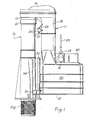
- Figure 1 is an elevation of an assembled siphon assembly, and
- Figure 2 is an exploded perspective view thereof.
- The siphon assembly is formed from plastics mouldings, the major components being first and
second portions 10, 11. -
First portion 10 constitutes the down leg of the assembled siphon U-shaped duct and is generally tubular, being provided with an externally threadedscrew connection 10a at its lower end which will be secured in the base of the cistern in use to mount the assembly therein and also form an outlet connection to a flush pipe or passage leading into a W.C. pan. The upper end ofportion 10 is formed as an increaseddiameter socket 12. - Second portion 11 comprises a cylindrical up
leg duct 15 leading to an invertedU top section 16, the other limb of the U being acylindrical spigot 17 which is operatively received in thesocket 12 of the first portion, fluid tight sealing thereof being assured by an "0"ring 18. - The lower part of the up leg of portion 11 is a generally
rectangular chamber 20 having a downwardly directedopen mouth 21 within which is positioned a piston and flexible diaphragm (not shown) of known kind operated by avertical pull rod 22 and link 23 which will be connected to a flushing lever of the cistern in use. - On assembly the up leg and down leg are aligned in spaced parallel relationship with the
mouth 21 ofchamber 20 adjacent to the lower end ofportion 10 and positioned just above the floor of the cistern. - The two portions are releasably secured together by securing means now described in detail.
- Each portion is provided with first formations in the form of
respective lugs portion 10 and one side of the upper end of theup leg 15 of portion 11 respectively. - When the portions are aligned in assembled relationship with
spigot 17 entered intosocket 12 bores inlugs pin 27 having an enlarged diameterbifurcated end 28 can be snap engaged through the lugs to retain them together. - The securing means further comprises mating second formations adjacent the lower ends of the two portions.
Portion 10 is provided with a verticallongitudinally extending rib 30 along approximately the lower half of its length projecting towards the side wall ofchamber 20 on assembly. This rib is shaped to a male profile by having, in cross section, an enlarged circular head portion connected to the main body of the down leg duct by a reduced cross section web. - A mating
female formation 31 is provided on the lower edge portion of a wall ofchamber 20 having a centralkeyhole section slot 32 forming a female profile which is slidingly engageable withrib 30 but which prevents relative lateral displacement of the two portions. To increase the stability of the interconnection,formation 31 extends laterally to each side ofslot 32 to provide aconcave face 33 which abuts the cylindrical outer surface ofportion 10 betweenlocation ribs 34 thereof. - The two portions can be readily assembled and disassembled without dismantling the cistern or disconnecting
first portion 10 therefrom by withdrawingpin 27 and then sliding portion 11 upwards so thatspigot 17 is drawn clear ofsocket 12, the upward movement being continued untilslot 32 offormation 31 clears the upper end of therib 30. The entire second portion can then be removed from the cistern together with the piston and diaphragm for maintenance or replacement. -
Portions 10 may be formed in various sizes i.e. of lengths to suit various patterns of cistern, and can be assembled together with second portions 11 having up legs of different lengths, the variations in length being accommodated by the sliding engagement offormation 31 with therib 30. Thus the spacing of themouth 21 from the floor of the cistern may be varied according to the components used and/or the effective length of the down ieg duct can be varied using a range of standard components and without special adaptation. - As in our said patent 2083851 forces acting on
chamber 20, e.g. aspull rod 22 is being operated, are transmitted to thefirst portion 10 and hence the cistern structure mainly through thepin 27, pivoting movments about that pin being resisted by the engagement between thesecond formations - It is to be noted that as the axis of the spigot and socket joint is vertical any upward or downward forces causing slight relative displacement will act along that axis and will not cause any damage or breaking of the fluid seal as the
spigot 17 can ride insidesocket 12. Moreover any slight pivotal movement aboutpin 27 due to clearance or manufacturing tolerances in the interengageable formations will generally be by way of anticlockwise movement of second portion 11 as viewed in the drawings due to upward pull onrod 22 and this will have the effect of shiftingspigot 17 into slightly deeper engagement withsocket 12. - In order to prevent any substantial amount of air being sucked in the top opening in
chamber 20 in whichpull rod 22 slides an open topped well 40 is moulded on the top ofchamber 20 to retain a reservoir of water surrounding the rod. - To provide controlled venting of the top of
chamber 20 to facilitate operation with high and low level suites a two-partremovable plug 41 is provided. With both parts of the plug inserted an opening in the chamber wall is entirely closed, but a central solid part of the plug can be removed to leave a restricted aperture through a remaining part of the plug for low level flushing, and the entire plug can be removed to leave a larger aperture for high level flushing, the two parts of the plug being interconnected by an integral flexible plastics band and the parts being marked with instructions for removal as above.
Claims (5)
Priority Applications (1)
| Application Number | Priority Date | Filing Date | Title |
|---|---|---|---|
| AT85305337T ATE39521T1 (en) | 1984-11-30 | 1985-07-26 | SIPHONE SYSTEM FOR SINK. |
Applications Claiming Priority (2)
| Application Number | Priority Date | Filing Date | Title |
|---|---|---|---|
| GB08430361A GB2167778B (en) | 1984-11-30 | 1984-11-30 | Syphon assembly for flushing cisterns |
| GB8430361 | 1984-11-30 |
Publications (3)
| Publication Number | Publication Date |
|---|---|
| EP0183337A2 EP0183337A2 (en) | 1986-06-04 |
| EP0183337A3 EP0183337A3 (en) | 1986-11-20 |
| EP0183337B1 true EP0183337B1 (en) | 1988-12-28 |
Family
ID=10570546
Family Applications (1)
| Application Number | Title | Priority Date | Filing Date |
|---|---|---|---|
| EP85305337A Expired EP0183337B1 (en) | 1984-11-30 | 1985-07-26 | Siphon assembly for flushing cisterns |
Country Status (10)
| Country | Link |
|---|---|
| US (1) | US4649953A (en) |
| EP (1) | EP0183337B1 (en) |
| AT (1) | ATE39521T1 (en) |
| AU (1) | AU575219B2 (en) |
| DE (1) | DE3567047D1 (en) |
| ES (1) | ES8609558A1 (en) |
| GB (1) | GB2167778B (en) |
| IE (1) | IE56963B1 (en) |
| IN (1) | IN164845B (en) |
| PT (1) | PT81044B (en) |
Families Citing this family (9)
| Publication number | Priority date | Publication date | Assignee | Title |
|---|---|---|---|---|
| GB9008226D0 (en) * | 1990-04-11 | 1990-06-13 | Polypipe Plc | Syphon apparatus |
| EP0488543A1 (en) * | 1990-11-27 | 1992-06-03 | Polypipe Plc | Syphon apparatus |
| GB2320262B (en) * | 1996-12-12 | 2000-10-11 | Dudley Thomas Ltd | Flushing cisterns |
| CA2230268A1 (en) * | 1997-02-25 | 1998-08-25 | David A. Saar | Siphon for tank type toilet |
| GB2358412B (en) * | 1997-02-25 | 2001-09-05 | Wade W Smith | Siphon for tank type toilet |
| US6473912B2 (en) | 2001-02-14 | 2002-11-05 | Jose-Jaime Preciado-Villanueva | Siphon flush apparatus |
| US20050120476A1 (en) * | 2003-12-08 | 2005-06-09 | Kennith Reid | Siphon tube for use with a toilet tank and bowl for maintaining a steady trickle flow of water through a supplying and unheated service line associated with the tank and bowl and method for installing the same |
| GB201316243D0 (en) * | 2013-09-12 | 2013-10-30 | Dudley Thomas Ltd | Syphon assembly and actuator therefor |
| DE102017121877A1 (en) * | 2017-09-21 | 2019-03-21 | Miele & Cie. Kg | Suction lifter for a wash-in box of a washing machine |
Family Cites Families (5)
| Publication number | Priority date | Publication date | Assignee | Title |
|---|---|---|---|---|
| GB801655A (en) * | 1956-07-17 | 1958-09-17 | Gen Electric Co Ltd | Improvements in or relating to siphons for flushing cisterns |
| AU408708B2 (en) * | 1965-09-20 | 1970-12-02 | An improved trap | |
| US3815941A (en) * | 1972-06-05 | 1974-06-11 | K Snyder | Yieldable connector for exhaust pipe sections |
| GB2083851B (en) * | 1980-09-06 | 1984-09-19 | Dudley Thomas Ltd | Siphonic unit for flushing cisterns |
| GB2092197A (en) * | 1981-01-29 | 1982-08-11 | Charmoy George Joseph Marie Ma | Cistern siphon units |
-
1984
- 1984-11-30 GB GB08430361A patent/GB2167778B/en not_active Expired
-
1985
- 1985-07-26 EP EP85305337A patent/EP0183337B1/en not_active Expired
- 1985-07-26 AT AT85305337T patent/ATE39521T1/en not_active IP Right Cessation
- 1985-07-26 DE DE8585305337T patent/DE3567047D1/en not_active Expired
- 1985-08-09 ES ES546045A patent/ES8609558A1/en not_active Expired
- 1985-08-28 PT PT81044A patent/PT81044B/en not_active IP Right Cessation
- 1985-09-30 IE IE2398/85A patent/IE56963B1/en unknown
- 1985-11-19 IN IN964/DEL/85A patent/IN164845B/en unknown
- 1985-11-19 AU AU50067/85A patent/AU575219B2/en not_active Ceased
- 1985-11-19 US US06/799,395 patent/US4649953A/en not_active Expired - Fee Related
Also Published As
| Publication number | Publication date |
|---|---|
| ES546045A0 (en) | 1986-07-16 |
| PT81044B (en) | 1987-08-19 |
| EP0183337A2 (en) | 1986-06-04 |
| PT81044A (en) | 1985-09-01 |
| AU5006785A (en) | 1986-06-05 |
| GB8430361D0 (en) | 1985-01-09 |
| IE56963B1 (en) | 1992-02-12 |
| GB2167778B (en) | 1988-02-03 |
| AU575219B2 (en) | 1988-07-21 |
| ATE39521T1 (en) | 1989-01-15 |
| IN164845B (en) | 1989-06-10 |
| GB2167778A (en) | 1986-06-04 |
| EP0183337A3 (en) | 1986-11-20 |
| IE852398L (en) | 1986-05-30 |
| DE3567047D1 (en) | 1989-02-02 |
| US4649953A (en) | 1987-03-17 |
| ES8609558A1 (en) | 1986-07-16 |
Similar Documents
| Publication | Publication Date | Title |
|---|---|---|
| US4649953A (en) | Siphon assembly for flushing cisterns | |
| US4449776A (en) | Electrical connector having opposed locking ramp members | |
| JPS622196B2 (en) | ||
| US20100276922A1 (en) | Coupling assembly | |
| JPS649512B2 (en) | ||
| EP4148313A1 (en) | Fluid connector with dry break | |
| US20220389697A1 (en) | Overflow pipe assembly | |
| GB2186021A (en) | Pivot joint | |
| US6192526B1 (en) | Top mounted flush valve for a toilet tank | |
| US20030146622A1 (en) | Pipe couplings | |
| BRPI0503774B1 (en) | ball joint connector | |
| CN214064151U (en) | Mechanism with quick joint and water inlet valve | |
| GB2270528A (en) | Dual-flush facility for syphonic flushing cistern | |
| PL172670B1 (en) | Branch coupler PL PL PL | |
| US6256801B1 (en) | Siphon assemblies | |
| EP1245902B1 (en) | Adapter for pipes for gas devices | |
| KR102524714B1 (en) | Angle valve for pipe mounting | |
| CN211229685U (en) | Swimming pool without bolt support | |
| EP0488543A1 (en) | Syphon apparatus | |
| CN219298356U (en) | Quick assembly disassembly's drain plug interlock | |
| GB2083851A (en) | Siphonic unit for flushing cisterns | |
| CN213673851U (en) | A quick detachable wrench assembly | |
| CN115748904B (en) | A quick-release drain plug linkage device | |
| KR200349676Y1 (en) | Joint device of sluice valve | |
| CN224201219U (en) | Mounting structure of vacuum breaker |
Legal Events
| Date | Code | Title | Description |
|---|---|---|---|
| PUAI | Public reference made under article 153(3) epc to a published international application that has entered the european phase |
Free format text: ORIGINAL CODE: 0009012 |
|
| AK | Designated contracting states |
Kind code of ref document: A2 Designated state(s): AT BE CH DE FR IT LI LU NL SE |
|
| PUAL | Search report despatched |
Free format text: ORIGINAL CODE: 0009013 |
|
| AK | Designated contracting states |
Kind code of ref document: A3 Designated state(s): AT BE CH DE FR IT LI LU NL SE |
|
| 17P | Request for examination filed |
Effective date: 19870508 |
|
| 17Q | First examination report despatched |
Effective date: 19880211 |
|
| GRAA | (expected) grant |
Free format text: ORIGINAL CODE: 0009210 |
|
| AK | Designated contracting states |
Kind code of ref document: B1 Designated state(s): AT BE CH DE FR IT LI LU NL SE |
|
| REF | Corresponds to: |
Ref document number: 39521 Country of ref document: AT Date of ref document: 19890115 Kind code of ref document: T |
|
| REF | Corresponds to: |
Ref document number: 3567047 Country of ref document: DE Date of ref document: 19890202 |
|
| ET | Fr: translation filed | ||
| ITF | It: translation for a ep patent filed | ||
| PG25 | Lapsed in a contracting state [announced via postgrant information from national office to epo] |
Ref country code: AT Effective date: 19890726 |
|
| PG25 | Lapsed in a contracting state [announced via postgrant information from national office to epo] |
Ref country code: SE Effective date: 19890727 |
|
| PG25 | Lapsed in a contracting state [announced via postgrant information from national office to epo] |
Ref country code: LU Free format text: LAPSE BECAUSE OF NON-PAYMENT OF DUE FEES Effective date: 19890731 Ref country code: LI Effective date: 19890731 Ref country code: CH Effective date: 19890731 Ref country code: BE Effective date: 19890731 |
|
| PLBE | No opposition filed within time limit |
Free format text: ORIGINAL CODE: 0009261 |
|
| STAA | Information on the status of an ep patent application or granted ep patent |
Free format text: STATUS: NO OPPOSITION FILED WITHIN TIME LIMIT |
|
| 26N | No opposition filed | ||
| BERE | Be: lapsed |
Owner name: THOMAS DUDLEY LTD Effective date: 19890731 |
|
| PG25 | Lapsed in a contracting state [announced via postgrant information from national office to epo] |
Ref country code: NL Effective date: 19900201 |
|
| NLV4 | Nl: lapsed or anulled due to non-payment of the annual fee | ||
| PG25 | Lapsed in a contracting state [announced via postgrant information from national office to epo] |
Ref country code: FR Free format text: LAPSE BECAUSE OF NON-PAYMENT OF DUE FEES Effective date: 19900330 |
|
| REG | Reference to a national code |
Ref country code: CH Ref legal event code: PL |
|
| PG25 | Lapsed in a contracting state [announced via postgrant information from national office to epo] |
Ref country code: DE Effective date: 19900403 |
|
| REG | Reference to a national code |
Ref country code: FR Ref legal event code: ST |
|
| EUG | Se: european patent has lapsed |
Ref document number: 85305337.9 Effective date: 19900418 |