EP0182604A1 - Joining insulated elongate conduit members - Google Patents
Joining insulated elongate conduit members Download PDFInfo
- Publication number
- EP0182604A1 EP0182604A1 EP85308273A EP85308273A EP0182604A1 EP 0182604 A1 EP0182604 A1 EP 0182604A1 EP 85308273 A EP85308273 A EP 85308273A EP 85308273 A EP85308273 A EP 85308273A EP 0182604 A1 EP0182604 A1 EP 0182604A1
- Authority
- EP
- European Patent Office
- Prior art keywords
- collar
- recoverable
- insulated
- elongate conduit
- pipe
- Prior art date
- Legal status (The legal status is an assumption and is not a legal conclusion. Google has not performed a legal analysis and makes no representation as to the accuracy of the status listed.)
- Granted
Links
Images


Classifications
-
- B—PERFORMING OPERATIONS; TRANSPORTING
- B29—WORKING OF PLASTICS; WORKING OF SUBSTANCES IN A PLASTIC STATE IN GENERAL
- B29C—SHAPING OR JOINING OF PLASTICS; SHAPING OF MATERIAL IN A PLASTIC STATE, NOT OTHERWISE PROVIDED FOR; AFTER-TREATMENT OF THE SHAPED PRODUCTS, e.g. REPAIRING
- B29C65/00—Joining or sealing of preformed parts, e.g. welding of plastics materials; Apparatus therefor
- B29C65/66—Joining or sealing of preformed parts, e.g. welding of plastics materials; Apparatus therefor by liberation of internal stresses, e.g. shrinking of one of the parts to be joined
- B29C65/68—Joining or sealing of preformed parts, e.g. welding of plastics materials; Apparatus therefor by liberation of internal stresses, e.g. shrinking of one of the parts to be joined using auxiliary shrinkable elements
-
- B—PERFORMING OPERATIONS; TRANSPORTING
- B29—WORKING OF PLASTICS; WORKING OF SUBSTANCES IN A PLASTIC STATE IN GENERAL
- B29C—SHAPING OR JOINING OF PLASTICS; SHAPING OF MATERIAL IN A PLASTIC STATE, NOT OTHERWISE PROVIDED FOR; AFTER-TREATMENT OF THE SHAPED PRODUCTS, e.g. REPAIRING
- B29C66/00—General aspects of processes or apparatus for joining preformed parts
- B29C66/01—General aspects dealing with the joint area or with the area to be joined
- B29C66/05—Particular design of joint configurations
- B29C66/10—Particular design of joint configurations particular design of the joint cross-sections
- B29C66/11—Joint cross-sections comprising a single joint-segment, i.e. one of the parts to be joined comprising a single joint-segment in the joint cross-section
- B29C66/114—Single butt joints
- B29C66/1142—Single butt to butt joints
-
- B—PERFORMING OPERATIONS; TRANSPORTING
- B29—WORKING OF PLASTICS; WORKING OF SUBSTANCES IN A PLASTIC STATE IN GENERAL
- B29C—SHAPING OR JOINING OF PLASTICS; SHAPING OF MATERIAL IN A PLASTIC STATE, NOT OTHERWISE PROVIDED FOR; AFTER-TREATMENT OF THE SHAPED PRODUCTS, e.g. REPAIRING
- B29C66/00—General aspects of processes or apparatus for joining preformed parts
- B29C66/50—General aspects of joining tubular articles; General aspects of joining long products, i.e. bars or profiled elements; General aspects of joining single elements to tubular articles, hollow articles or bars; General aspects of joining several hollow-preforms to form hollow or tubular articles
- B29C66/51—Joining tubular articles, profiled elements or bars; Joining single elements to tubular articles, hollow articles or bars; Joining several hollow-preforms to form hollow or tubular articles
- B29C66/52—Joining tubular articles, bars or profiled elements
- B29C66/522—Joining tubular articles
- B29C66/5221—Joining tubular articles for forming coaxial connections, i.e. the tubular articles to be joined forming a zero angle relative to each other
-
- B—PERFORMING OPERATIONS; TRANSPORTING
- B29—WORKING OF PLASTICS; WORKING OF SUBSTANCES IN A PLASTIC STATE IN GENERAL
- B29C—SHAPING OR JOINING OF PLASTICS; SHAPING OF MATERIAL IN A PLASTIC STATE, NOT OTHERWISE PROVIDED FOR; AFTER-TREATMENT OF THE SHAPED PRODUCTS, e.g. REPAIRING
- B29C66/00—General aspects of processes or apparatus for joining preformed parts
- B29C66/50—General aspects of joining tubular articles; General aspects of joining long products, i.e. bars or profiled elements; General aspects of joining single elements to tubular articles, hollow articles or bars; General aspects of joining several hollow-preforms to form hollow or tubular articles
- B29C66/51—Joining tubular articles, profiled elements or bars; Joining single elements to tubular articles, hollow articles or bars; Joining several hollow-preforms to form hollow or tubular articles
- B29C66/52—Joining tubular articles, bars or profiled elements
- B29C66/522—Joining tubular articles
- B29C66/5224—Joining tubular articles for forming fork-shaped connections, e.g. for making Y-shaped pieces
-
- B—PERFORMING OPERATIONS; TRANSPORTING
- B29—WORKING OF PLASTICS; WORKING OF SUBSTANCES IN A PLASTIC STATE IN GENERAL
- B29C—SHAPING OR JOINING OF PLASTICS; SHAPING OF MATERIAL IN A PLASTIC STATE, NOT OTHERWISE PROVIDED FOR; AFTER-TREATMENT OF THE SHAPED PRODUCTS, e.g. REPAIRING
- B29C66/00—General aspects of processes or apparatus for joining preformed parts
- B29C66/70—General aspects of processes or apparatus for joining preformed parts characterised by the composition, physical properties or the structure of the material of the parts to be joined; Joining with non-plastics material
- B29C66/72—General aspects of processes or apparatus for joining preformed parts characterised by the composition, physical properties or the structure of the material of the parts to be joined; Joining with non-plastics material characterised by the structure of the material of the parts to be joined
- B29C66/723—General aspects of processes or apparatus for joining preformed parts characterised by the composition, physical properties or the structure of the material of the parts to be joined; Joining with non-plastics material characterised by the structure of the material of the parts to be joined being multi-layered
-
- F—MECHANICAL ENGINEERING; LIGHTING; HEATING; WEAPONS; BLASTING
- F16—ENGINEERING ELEMENTS AND UNITS; GENERAL MEASURES FOR PRODUCING AND MAINTAINING EFFECTIVE FUNCTIONING OF MACHINES OR INSTALLATIONS; THERMAL INSULATION IN GENERAL
- F16L—PIPES; JOINTS OR FITTINGS FOR PIPES; SUPPORTS FOR PIPES, CABLES OR PROTECTIVE TUBING; MEANS FOR THERMAL INSULATION IN GENERAL
- F16L59/00—Thermal insulation in general
- F16L59/14—Arrangements for the insulation of pipes or pipe systems
- F16L59/16—Arrangements specially adapted to local requirements at flanges, junctions, valves or the like
- F16L59/18—Arrangements specially adapted to local requirements at flanges, junctions, valves or the like adapted for joints
- F16L59/182—Joints with sleeve or socket
-
- B—PERFORMING OPERATIONS; TRANSPORTING
- B29—WORKING OF PLASTICS; WORKING OF SUBSTANCES IN A PLASTIC STATE IN GENERAL
- B29C—SHAPING OR JOINING OF PLASTICS; SHAPING OF MATERIAL IN A PLASTIC STATE, NOT OTHERWISE PROVIDED FOR; AFTER-TREATMENT OF THE SHAPED PRODUCTS, e.g. REPAIRING
- B29C66/00—General aspects of processes or apparatus for joining preformed parts
- B29C66/01—General aspects dealing with the joint area or with the area to be joined
- B29C66/05—Particular design of joint configurations
- B29C66/10—Particular design of joint configurations particular design of the joint cross-sections
- B29C66/11—Joint cross-sections comprising a single joint-segment, i.e. one of the parts to be joined comprising a single joint-segment in the joint cross-section
- B29C66/116—Single bevelled joints, i.e. one of the parts to be joined being bevelled in the joint area
-
- B—PERFORMING OPERATIONS; TRANSPORTING
- B29—WORKING OF PLASTICS; WORKING OF SUBSTANCES IN A PLASTIC STATE IN GENERAL
- B29C—SHAPING OR JOINING OF PLASTICS; SHAPING OF MATERIAL IN A PLASTIC STATE, NOT OTHERWISE PROVIDED FOR; AFTER-TREATMENT OF THE SHAPED PRODUCTS, e.g. REPAIRING
- B29C66/00—General aspects of processes or apparatus for joining preformed parts
- B29C66/70—General aspects of processes or apparatus for joining preformed parts characterised by the composition, physical properties or the structure of the material of the parts to be joined; Joining with non-plastics material
- B29C66/71—General aspects of processes or apparatus for joining preformed parts characterised by the composition, physical properties or the structure of the material of the parts to be joined; Joining with non-plastics material characterised by the composition of the plastics material of the parts to be joined
-
- B—PERFORMING OPERATIONS; TRANSPORTING
- B29—WORKING OF PLASTICS; WORKING OF SUBSTANCES IN A PLASTIC STATE IN GENERAL
- B29C—SHAPING OR JOINING OF PLASTICS; SHAPING OF MATERIAL IN A PLASTIC STATE, NOT OTHERWISE PROVIDED FOR; AFTER-TREATMENT OF THE SHAPED PRODUCTS, e.g. REPAIRING
- B29C66/00—General aspects of processes or apparatus for joining preformed parts
- B29C66/70—General aspects of processes or apparatus for joining preformed parts characterised by the composition, physical properties or the structure of the material of the parts to be joined; Joining with non-plastics material
- B29C66/72—General aspects of processes or apparatus for joining preformed parts characterised by the composition, physical properties or the structure of the material of the parts to be joined; Joining with non-plastics material characterised by the structure of the material of the parts to be joined
- B29C66/727—General aspects of processes or apparatus for joining preformed parts characterised by the composition, physical properties or the structure of the material of the parts to be joined; Joining with non-plastics material characterised by the structure of the material of the parts to be joined being porous, e.g. foam
-
- B—PERFORMING OPERATIONS; TRANSPORTING
- B29—WORKING OF PLASTICS; WORKING OF SUBSTANCES IN A PLASTIC STATE IN GENERAL
- B29L—INDEXING SCHEME ASSOCIATED WITH SUBCLASS B29C, RELATING TO PARTICULAR ARTICLES
- B29L2023/00—Tubular articles
- B29L2023/22—Tubes or pipes, i.e. rigid
- B29L2023/225—Insulated
-
- Y—GENERAL TAGGING OF NEW TECHNOLOGICAL DEVELOPMENTS; GENERAL TAGGING OF CROSS-SECTIONAL TECHNOLOGIES SPANNING OVER SEVERAL SECTIONS OF THE IPC; TECHNICAL SUBJECTS COVERED BY FORMER USPC CROSS-REFERENCE ART COLLECTIONS [XRACs] AND DIGESTS
- Y10—TECHNICAL SUBJECTS COVERED BY FORMER USPC
- Y10S—TECHNICAL SUBJECTS COVERED BY FORMER USPC CROSS-REFERENCE ART COLLECTIONS [XRACs] AND DIGESTS
- Y10S264/00—Plastic and nonmetallic article shaping or treating: processes
- Y10S264/71—Processes of shaping by shrinking
Definitions
- This invention relates to an insulated elongate conduit member and an assembly for, and a method of joining insulated elongate conduit members.
- the invention is particularly but not exclusively suitable for joining insulated pipes.
- the invention relates in general to the joining of insulated elongate conduit members, the description below will relate primarily, for convenience and not by way of limitation, to the joining of thermally insulated pipes, suitable for use in a district heating system, or a district cooling system.
- the end portion of an insulated pipe has been bared of insulation to facilitate joining to the bared end portion of another insulated pipe by for example welding, brazing or soldering. It is then necessary to reinsulate the bared pipes in the region of the joint.
- One method that has been used to reinsulate the bare portion of the pipes is to position a tubular case around said bare portion, introduce insulating foam to fill the cavity surrounding the bare portion through an opening in the case, and then provide an environmental sealing layer, of for example heat-recoverable polymeric material, around the case.
- One major disadvantage however, is that a different size case must be provided for each different sized insulated pipe; this means that a large inventory must be carried.
- Another problem is that the introduction of foam into the cavity within the case around the pipe joint does not always lead to a well insulated joint, and the foaming process itself is potentially hazardous to the operator. Yet another problem is that the method described above is time-consuming.
- a further problem lies in the vulnerability of the bare ends of insulated pipes to damage before installation, which can result in a pipe being substantially weakened, or deformed to an extent that it cannot be joined to the end of another pipe.
- the present invention provides an insulated elongate conduit member, which is arranged so that connection to the member or inter-connection of two such members, may be effected in a particularly convenient manner, without subsequently having to create a layer of insulation around the connection.
- the present invention provides an elongate conduit member covered with insulating material, wherein at at least one end of the member, the insulating material is provided with an annular recess surrounding the member thereby exposing a portion of the member at the said end, to allow access for connection thereto.
- the invention is applicable to, inter alia thermally insulated pipes, for example pipes carrying water, including district heating pipes and district cooling pipes, or pipes carrying oil products.
- the invention is applicable inter alia to preinsulated metal pipes, and to preinsulated polymeric pipes, for example preinsulated polyethylene pipes.
- Preferably the end of the conduit member and the end of the insulating material are substantially coplanar, or at least they are arranged such that the conduit member does not extend beyond the end of the insulation material.
- the insulated elongate conduit member is preferably provided with a connecting collar adapted to fit the annular recess, for example, a recoverable tubular connecting collar, for effecting connection to the member and, for example, another of said elongate conduit members.
- the invention provides an assembly comprising at least two insulated elongate conduit members, wherein at at least one end of each insulated member, the insulating material is provided with an annular recess surrounding the member, thereby exposing the end of the member to allow access for connection thereto; and at least one recoverable tubular connecting collar suitable for effecting inter- connection of said ends of said members, and adapted to be located within the annular recesses surrounding said ends.
- the present invention also provides a method of connecting an insulated elongate conduit member in which at at least one end of said member, the insulating material is provided with an annular recess surrounding the member, thereby exposing a portion of the member at the said end to allow access for connection thereto, the method comprising positioning a recoverable connecting collar within the annular recess such that it surrounds the exposed end portion of the elongate member, and recovering the collar into connecting engagement with the exposed end portion.
- the method of the invention may be used, for example, to interconnect insulated elongate conduit members, such as insulated pipes, or to connect an insulated pipe to an outlet on the central boiler or refrigerator of a district heating system or a district cooling system respectively.
- a recoverable article an article whose dimensional configuration may be made to change when subjected to an appropriate treatment.
- these articles recover towards an original shape from which they have previously been deformed but the term "recoverable”, as used herein also includes an article which adopts a new configuration, even if it has not been previously deformed.
- the article may be heat recoverable, such that its dimensional configuration may be made to change when subjected to heat treatment.
- tubular as used herein to describe a recoverable member, includes both right circular cylindrical hollow members, and also members of irregular and/or of varying cross-section as well as, for example, members of Y-shaped, T-shaped and X-shaped cross-section.
- the recoverable tubular connecting collar may comprise metallic and/or polymeric material.
- Recoverable metals are often referred to as "memory metals" or “memory alloys” and are metallic materials which exhibit changes in strength and configurational characteristics on passing through a transition temperature, in most cases the transition temperature between the martensitic and austenitic states, and can be used to make heat recoverable articles by deforming an article made from them whilst the metal is in its martensitic, low temperature state. The article will retain its deformed configuration until it is warmed above the transition temperature to the austenitic state when it will return or attempt to return towards its original configuration. It will be understood that the heat-recoverable article is capable of returning towards its original configuration without the further application of outside forces.
- a collar comprising memory metal to effect interconnection of the elongate conduit members of the invention has the advantage that the operator sensitive process of, for example welding is avoided.
- the collar comprises a nickel-titanium alloy, which exerts a particularly large recovery force.
- connecting collars comprising at least in part memory metal and which are suitable for connecting to elongate members of the present invention
- connecting collars which incorporate various gripping means, for example, a tubular collar may be provided with circumferential inwardly projecting teeth on its inner surface, or with a liner, itself provided with teeth.
- a layer of a sealant, having dispersed therein a particulate filler which is adapted to bite into the elongate, member on recovery of the recoverable collar may be located inside the collar.
- An alternative form of connecting collar is described in UK published Patent application no.
- 2042819A which comprises a substantially tubular insert, positioned within at least one recoverable driver, and arranged to receive the ends of the elongate members to be connected within it.
- the connecting collar described in the above-mentioned specifications are referred to by way of example only, and not by way of limitation. It is to be understood that other forms of recoverable connecting collars may be used in the present invention.
- the recoverable tubular connecting collar comprises a recoverable polymeric material.
- a conductive polymeric material is used, which can be heated to its recovery temperature by passing electric current through the polymer. By appropriate electroding the current can be caused to flow between the ends of the conductive polymeric collar, or alternatively, through the thickness of the collar.
- the polymeric material is sintered. It is particularly preferred to use a collar comprising sintered ultra high molecular weight polyethylene, preferably having carbon black dispersed therein.
- the polymeric material may, but need not necessarily, be cross-linked. Suitable polymeric collars, and use thereof, are disclosed in European patent application no. 85302326.5.
- the polymeric collar is preferably arranged to adhere directly or indirectly to the insulation-free end portion of the or each elongate conduit member, to effect interconnection of the conduit members.
- a collar comprising recoverable polymeric material for joining conduit members that are made of a material that is fusible with the polymeric material of the collar.
- a polymeric collar to join polymeric conduit members, for example polyethylene pipes.
- the recoverable collar is preferably heated to its recovery temperature to cause the collar to recover to contact the conduit members; heating is then continued to cause fusion between the collar and the conduit members.
- the outside of the recoverable collar slidingly engages the longitudinally extending surface of the insulating material which defines the recess.
- the diameter of the recess, and also of a recoverable collar with a wall thickness of 0.4 cm prior to recovery, is preferably in the range of 8.6 to 8.9 cm while after recovery, the outer diameter of the collar will be 8.3 cm.
- the space between the collar and said surface after recovery of the collar is relatively small, and the insulation around the completed joint is substantially the same as that around the remainder of the conduit.
- the axial length of the annular recess is substantially equal to half the axial length of the recoverable collar.
- This arrangement has the advantage that the collar can be positively axially engaged within the recesses around the two conduit members which are to be jointed thereby minimising the chance of a bad joint caused by a misplaced collar.
- this arrangement has the advantage that conduit members are brought into abutting contact, so that there is no space remaining between the insulation of the joined members. It is preferred that there is a recess in the insulation at each end of a conduit member to enable a connection, for example an inter-connection, to be made at each end of said member.
- connection may be effected by means of one or more recoverable connecting collars in conjunction with a deformable tubular connecting member.
- the connecting member is placed around an end of a conduit member to be joined within the annular space in the insulation, and the recoverable collar is placed around the connecting member and the conduit member such that, on recovery of the collar, the connecting member is deformed inwardly into sealing engagement with the underlying conduit member.
- the deformable connecting member may be joined, at another end, to another conduit member by means of another recoverable collar.
- the conduit member of the invention may comprise, at at least one end, a connecting member which is aranged to receive an end portion of another conduit member, for example the connecting member may be connected to a conduit member, for example, by welding or by means of an adhesive, or the connecting member may be formed as a swaged end portion of the conduit member, within which the end portion of another conduit member can be positioned prior to inward deformation of the swaged end portion by a recoverable collar.
- a deformable connecting member it may comprise metallic or polymeric material.
- the connecting member will generally have a cylindrical cross-section, and it may be straight or have an X, Y, T or other to suit the pipe configuration.
- the connecting member may be provided with teeth, an adhesive liner or another adaptation to enhance its ability to seal to the underlying conduit. It is particularly preferred to use, as a connecting member, a steel tube which can be welded at one end to an elongate conduit member, and deformed at another end into sealing engagement with another conduit member.
- the joint between the members is well insulated by the original insulating material, which additionally provides a smooth profile on to which an outer protecting cover may be applied.
- the process of introducing insulating material into a cavity around the joint, being time-consuming, operator sensitive and potentially hazardous, may be completely avoided.
- the insulation in the region of the joint is protected by means of a recoverable sleeve, which may have a tubular configuration, or alternatively, it may be in the form of a sheet which is wrapped around the joint and its ends secured together.
- a recoverable sleeve which may have a tubular configuration, or alternatively, it may be in the form of a sheet which is wrapped around the joint and its ends secured together.
- the sleeve is heat-recoverable; in their most common form, such sleeves are made from polymeric material exhibiting the property of elastic or plastic memory, as described for example in US Patents 2027962, 3086242 and 3597372. As it is made clear in, for example, US Patent No.
- the original heat-stable form may be a transient form in a continuous process in which, for example, an extruded tube is expanded whilst hot to a dimensionally heat-unstable form, but in other applications, a preformed dimensionally heat-stable article is deformed to a dimensionally heat unstable form in a separate stage.
- the heat-recoverable sleeve is provided with a layer of sealing material, which may comprise an adhesive, for example a polyamide resin, a water- insoluble sealant such as a mastic, or both, on the surface which contacts the jointed elongate members.
- a suitable sleeve is described in British published Patent Application 2108625A.
- a joint may be effected between any number of insulated elongate conduit members by appropriate choice of connecting collar. For example, if two such members are to be jointed, a collar with substantially uniform cross-section is appropriate, whereas if three members are to be jointed a 'T' -shaped, or a 'Y'-shaped collar would be used.
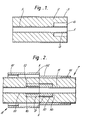
- Figure 1 shows the end portion of an insulated pipe which may be a district heating pipe, in which a pipe 1 is insulated by a surrounding layer 2 of polyurethane foam, which is protected by an environmental sealing layer 3 of polyethylene.
- a length 4 of pipe 1, adjacent to the end 5 of the insulated pipe is left bare of insulation, such that there is an annular recess 6 around the pipe.
- FIG 2 shows stages in the jointing of two thermally insulated pipes, each according to Figure 1, indicated respectively at 7 and 8.
- a first portion of a heat-recoverable connecting collar 9 comprising a nickel-titanium alloy which exhibits the property of memory, is slid into the annular recess 10, and surrounds the pipe 11 of one insulated pipe 7 while in its expanded, martensitic state.
- the axial length of the recess 10 is substantially equal to half the axial length of the unrecovered collar 9.
- the second insulated pipe 8 is brought into abutting contact with the first insulated pipe, such that a second portion of the expanded collar 9 is slid into the annular recess 12, and thus surrounds the pipe 13 of the second insulated pipe 8.
- the axial length of the recess 12 is substantially equal to half of the axial length of the unrecovered collar 9 so that the ends of the collar abut the insulation at the ends 16 of the annular recesses, 10 and 12.
- the collar 9 is recovered to its radially contracted, austenitic state by raising the temperature of the memory metal above -80°C which is the transition temperature of the nickel-titanium alloy. In the austenitic state, the collar grips the pipes 11 and 13, and holds the insulating pipes 7 and 8, in abutting contact.
- a polymeric heat-recoverable wrap-around sleeve 14, provided with an internal layer of sealing material 15 is positioned around the joint, and heated, causing it to shrink and sealingly engage the outer surface of the jointed insulated pipes, 7 and 8.
- Figure 3 shows three thermally insulated pipes, indicated generally at 17, 18 and 19, jointed by means of a 'Y'-shaped heat-recoverable collar 20. The joint is covered by a 'Y'-shaped heat-recoverable sleeve 21.
- Figure 4 shows a joint between two district heating pipes 40,42, which employs a deformable tubular connecting member 44.
- the member 44 is welded at a first end 45 to one of the pipes 40, and tapers outwardly towards its other end 46, towards which end it is provided with inwardly facing teeth 47.
- the insulation 48, around the pipe 40, is provided with an annular recess 50 around the end 46 of the connecting member 44 and the pipe 42 is arranged such that the end portion is left bare of thermal insulation.
- the joint between pipes 40,42 is made by positioning a heat recoverable metal connecting collar 52 around the connecting member 44 within the recess 50, and then bringing the pipes 40,42 substantially into abuttment with the end portion of the pipe 42 within the connecting member 44. Subsequent recovery of the collar 52 deforms the member 44 so as to form a seal with the outer surface of pipe 42, the teeth 47 enhancing the seal.
- the resulting pipe joint is made water tight by means of a recoverable sleeve 54, coated with adhesive or mastic or preferably both.
- the welded connecting member 44 may extend beyond the end of pipe 40, and pipe 42 may have an annular recess in the insulation around its end within which to receive the end 46 of the connecting member 44.
Abstract
Description
- This invention relates to an insulated elongate conduit member and an assembly for, and a method of joining insulated elongate conduit members. The invention is particularly but not exclusively suitable for joining insulated pipes. Although the invention relates in general to the joining of insulated elongate conduit members, the description below will relate primarily, for convenience and not by way of limitation, to the joining of thermally insulated pipes, suitable for use in a district heating system, or a district cooling system.
- In the installation of insulated pipes comprising a fluid conveying pipe, and a covering layer of thermal insulation, it is necessary to make joints between adjacent sections of pipe. After joining the pipes, it is necessary to ensure that there is adequate thermal insulation around the joint in order to minimise heat losses from the system.
- Hitherto, the end portion of an insulated pipe has been bared of insulation to facilitate joining to the bared end portion of another insulated pipe by for example welding, brazing or soldering. It is then necessary to reinsulate the bared pipes in the region of the joint. One method that has been used to reinsulate the bare portion of the pipes is to position a tubular case around said bare portion, introduce insulating foam to fill the cavity surrounding the bare portion through an opening in the case, and then provide an environmental sealing layer, of for example heat-recoverable polymeric material, around the case. One major disadvantage, however, is that a different size case must be provided for each different sized insulated pipe; this means that a large inventory must be carried. Another problem is that the introduction of foam into the cavity within the case around the pipe joint does not always lead to a well insulated joint, and the foaming process itself is potentially hazardous to the operator. Yet another problem is that the method described above is time-consuming.
- A further problem lies in the vulnerability of the bare ends of insulated pipes to damage before installation, which can result in a pipe being substantially weakened, or deformed to an extent that it cannot be joined to the end of another pipe.
- The present invention provides an insulated elongate conduit member, which is arranged so that connection to the member or inter-connection of two such members, may be effected in a particularly convenient manner, without subsequently having to create a layer of insulation around the connection.
- Accordingly, in one aspect, the present invention provides an elongate conduit member covered with insulating material, wherein at at least one end of the member, the insulating material is provided with an annular recess surrounding the member thereby exposing a portion of the member at the said end, to allow access for connection thereto.
- The invention is applicable to, inter alia thermally insulated pipes, for example pipes carrying water, including district heating pipes and district cooling pipes, or pipes carrying oil products. The invention is applicable inter alia to preinsulated metal pipes, and to preinsulated polymeric pipes, for example preinsulated polyethylene pipes. Preferably the end of the conduit member and the end of the insulating material are substantially coplanar, or at least they are arranged such that the conduit member does not extend beyond the end of the insulation material.
- The insulated elongate conduit member is preferably provided with a connecting collar adapted to fit the annular recess, for example, a recoverable tubular connecting collar, for effecting connection to the member and, for example, another of said elongate conduit members.
- In its second aspect, the invention provides an assembly comprising at least two insulated elongate conduit members, wherein at at least one end of each insulated member, the insulating material is provided with an annular recess surrounding the member, thereby exposing the end of the member to allow access for connection thereto; and at least one recoverable tubular connecting collar suitable for effecting inter- connection of said ends of said members, and adapted to be located within the annular recesses surrounding said ends.
- The present invention also provides a method of connecting an insulated elongate conduit member in which at at least one end of said member, the insulating material is provided with an annular recess surrounding the member, thereby exposing a portion of the member at the said end to allow access for connection thereto, the method comprising positioning a recoverable connecting collar within the annular recess such that it surrounds the exposed end portion of the elongate member, and recovering the collar into connecting engagement with the exposed end portion.
- The method of the invention may be used, for example, to interconnect insulated elongate conduit members, such as insulated pipes, or to connect an insulated pipe to an outlet on the central boiler or refrigerator of a district heating system or a district cooling system respectively.
- By a recoverable article is meant an article whose dimensional configuration may be made to change when subjected to an appropriate treatment. Usually these articles recover towards an original shape from which they have previously been deformed but the term "recoverable", as used herein also includes an article which adopts a new configuration, even if it has not been previously deformed. The article may be heat recoverable, such that its dimensional configuration may be made to change when subjected to heat treatment.
- The term "tubular", as used herein to describe a recoverable member, includes both right circular cylindrical hollow members, and also members of irregular and/or of varying cross-section as well as, for example, members of Y-shaped, T-shaped and X-shaped cross-section.
- The recoverable tubular connecting collar may comprise metallic and/or polymeric material. Recoverable metals are often referred to as "memory metals" or "memory alloys" and are metallic materials which exhibit changes in strength and configurational characteristics on passing through a transition temperature, in most cases the transition temperature between the martensitic and austenitic states, and can be used to make heat recoverable articles by deforming an article made from them whilst the metal is in its martensitic, low temperature state. The article will retain its deformed configuration until it is warmed above the transition temperature to the austenitic state when it will return or attempt to return towards its original configuration. It will be understood that the heat-recoverable article is capable of returning towards its original configuration without the further application of outside forces.
- Amongst such memory metals there may especially be mentioned various alloys of titanium and nickel which are described, for example in U.S. Patent Nos. 3174851, 3351463, 3753700, 3759552, British Patent Nos. 1327441 and 1327442 and NASA Publication SP 110, "55-Nitinol - The Alloy with a Memory, etc." (U.S. Government Printing Office, Washington, D.C. 1972). The property of heat-recoverability has not however, been solely confined to such as titanium-nickel alloys. Thus, for example, various beta-brass alloys have been demonstrated to exhibit this property in, e.g. N. Nakanishi et al Scripta Metallurgica 5 433-440 (Pergamon Press 1971), U.S. Patent Nos 3783037, 4019925, 4144104, 4146392 and 4166739, and such materials may be doped to lower their transition temperature to cryogenic regimes by know techniques. Similarly, 304 stainless steels have been shown to enjoy such characteristics E Enami et al, id, at pp. 663-68.
- The use of a collar comprising memory metal to effect interconnection of the elongate conduit members of the invention has the advantage that the operator sensitive process of, for example welding is avoided. Advantageously, the collar comprises a nickel-titanium alloy, which exerts a particularly large recovery force.
- Examples of connecting collars comprising at least in part memory metal and which are suitable for connecting to elongate members of the present invention, are described in UK Patent Nos. 1327441, 1488393, 1518788 and 2039654B. These specifications describe connecting collars which incorporate various gripping means, for example, a tubular collar may be provided with circumferential inwardly projecting teeth on its inner surface, or with a liner, itself provided with teeth. A layer of a sealant, having dispersed therein a particulate filler which is adapted to bite into the elongate, member on recovery of the recoverable collar may be located inside the collar. An alternative form of connecting collar is described in UK published Patent application no. 2042819A, which comprises a substantially tubular insert, positioned within at least one recoverable driver, and arranged to receive the ends of the elongate members to be connected within it. The connecting collar described in the above-mentioned specifications are referred to by way of example only, and not by way of limitation. It is to be understood that other forms of recoverable connecting collars may be used in the present invention.
- In another embodiment, the recoverable tubular connecting collar comprises a recoverable polymeric material. Preferably a conductive polymeric material is used, which can be heated to its recovery temperature by passing electric current through the polymer. By appropriate electroding the current can be caused to flow between the ends of the conductive polymeric collar, or alternatively, through the thickness of the collar. Preferably the polymeric material is sintered. It is particularly preferred to use a collar comprising sintered ultra high molecular weight polyethylene, preferably having carbon black dispersed therein. The polymeric material may, but need not necessarily, be cross-linked. Suitable polymeric collars, and use thereof, are disclosed in European patent application no. 85302326.5.
- The polymeric collar is preferably arranged to adhere directly or indirectly to the insulation-free end portion of the or each elongate conduit member, to effect interconnection of the conduit members.
- It is particularly advantageous to use a collar comprising recoverable polymeric material for joining conduit members that are made of a material that is fusible with the polymeric material of the collar. Thus, for example, it is particularly advantageous to use a polymeric collar to join polymeric conduit members, for example polyethylene pipes. In such cases the recoverable collar is preferably heated to its recovery temperature to cause the collar to recover to contact the conduit members; heating is then continued to cause fusion between the collar and the conduit members.
- In a preferred embodiment, the outside of the recoverable collar slidingly engages the longitudinally extending surface of the insulating material which defines the recess. For example, in the case of an insulated pipe with an external diameter of 20 cm in which the conduit has an external diameter of 7.5 cm, the diameter of the recess, and also of a recoverable collar with a wall thickness of 0.4 cm, prior to recovery, is preferably in the range of 8.6 to 8.9 cm while after recovery, the outer diameter of the collar will be 8.3 cm. Thus, the space between the collar and said surface after recovery of the collar is relatively small, and the insulation around the completed joint is substantially the same as that around the remainder of the conduit.
- In addition, in the case of a joint between two elongate conduit members the axial length of the annular recess is substantially equal to half the axial length of the recoverable collar. This arrangement has the advantage that the collar can be positively axially engaged within the recesses around the two conduit members which are to be jointed thereby minimising the chance of a bad joint caused by a misplaced collar. In addition, this arrangement has the advantage that conduit members are brought into abutting contact, so that there is no space remaining between the insulation of the joined members. It is preferred that there is a recess in the insulation at each end of a conduit member to enable a connection, for example an inter-connection, to be made at each end of said member.
- In an alternative embodiment, the connection may be effected by means of one or more recoverable connecting collars in conjunction with a deformable tubular connecting member. In use, the connecting member is placed around an end of a conduit member to be joined within the annular space in the insulation, and the recoverable collar is placed around the connecting member and the conduit member such that, on recovery of the collar, the connecting member is deformed inwardly into sealing engagement with the underlying conduit member. The deformable connecting member may be joined, at another end, to another conduit member by means of another recoverable collar. Alternatively or in addition, the conduit member of the invention may comprise, at at least one end, a connecting member which is aranged to receive an end portion of another conduit member, for example the connecting member may be connected to a conduit member, for example, by welding or by means of an adhesive, or the connecting member may be formed as a swaged end portion of the conduit member, within which the end portion of another conduit member can be positioned prior to inward deformation of the swaged end portion by a recoverable collar. When a deformable connecting member is used, it may comprise metallic or polymeric material. The connecting member will generally have a cylindrical cross-section, and it may be straight or have an X, Y, T or other to suit the pipe configuration. The connecting member may be provided with teeth, an adhesive liner or another adaptation to enhance its ability to seal to the underlying conduit. It is particularly preferred to use, as a connecting member, a steel tube which can be welded at one end to an elongate conduit member, and deformed at another end into sealing engagement with another conduit member.
- When the present invention provides a joint, for example between two elongate conduit members, it will be appreciated that the joint between the members is well insulated by the original insulating material, which additionally provides a smooth profile on to which an outer protecting cover may be applied. Thus the process of introducing insulating material into a cavity around the joint, being time-consuming, operator sensitive and potentially hazardous, may be completely avoided.
- In a preferred embodiment of a joint provided by the present invention, the insulation in the region of the joint is protected by means of a recoverable sleeve, which may have a tubular configuration, or alternatively, it may be in the form of a sheet which is wrapped around the joint and its ends secured together. Preferably, the sleeve is heat-recoverable; in their most common form, such sleeves are made from polymeric material exhibiting the property of elastic or plastic memory, as described for example in US Patents 2027962, 3086242 and 3597372. As it is made clear in, for example, US Patent No. 2027962, the original heat-stable form may be a transient form in a continuous process in which, for example, an extruded tube is expanded whilst hot to a dimensionally heat-unstable form, but in other applications, a preformed dimensionally heat-stable article is deformed to a dimensionally heat unstable form in a separate stage.
- Preferably, the heat-recoverable sleeve is provided with a layer of sealing material, which may comprise an adhesive, for example a polyamide resin, a water- insoluble sealant such as a mastic, or both, on the surface which contacts the jointed elongate members. A suitable sleeve is described in British published Patent Application 2108625A.
- A joint may be effected between any number of insulated elongate conduit members by appropriate choice of connecting collar. For example, if two such members are to be jointed, a collar with substantially uniform cross-section is appropriate, whereas if three members are to be jointed a 'T' -shaped, or a 'Y'-shaped collar would be used.
- An assembly comprising an insulated elongate conduit member and a method of forming a connection thereto, each in accordance with the present invention, will now be described, by way of example only, with reference to the accompanying drawings, in which:
- Figure 1 is a section through one end of a thermally insulated pipe which constitutes the insulated elongate conduit member;
- Figure 2 is a section through a joint between two thermally insulated pipes, each according to Figure 1, wherein the dotted line A-A divides the figure into two parts showing respectively the components before and after jointing of the pipes;
- Figure 3 is a section through a joint between three thermally insulated pipes, each according to Figure 1; and
- Figure 4 is a section through a joint between two thermally insulated pipes, using a deformable connecting member.
- Referring to the drawings, Figure 1 shows the end portion of an insulated pipe which may be a district heating pipe, in which a pipe 1 is insulated by a surrounding layer 2 of polyurethane foam, which is protected by an
environmental sealing layer 3 of polyethylene. A length 4 of pipe 1, adjacent to the end 5 of the insulated pipe is left bare of insulation, such that there is an annular recess 6 around the pipe. - Figure 2 shows stages in the jointing of two thermally insulated pipes, each according to Figure 1, indicated respectively at 7 and 8. A first portion of a heat-recoverable connecting collar 9 comprising a nickel-titanium alloy which exhibits the property of memory, is slid into the
annular recess 10, and surrounds thepipe 11 of oneinsulated pipe 7 while in its expanded, martensitic state. The axial length of therecess 10 is substantially equal to half the axial length of the unrecovered collar 9. The second insulated pipe 8 is brought into abutting contact with the first insulated pipe, such that a second portion of the expanded collar 9 is slid into theannular recess 12, and thus surrounds thepipe 13 of the second insulated pipe 8. The axial length of therecess 12 is substantially equal to half of the axial length of the unrecovered collar 9 so that the ends of the collar abut the insulation at theends 16 of the annular recesses, 10 and 12. The collar 9 is recovered to its radially contracted, austenitic state by raising the temperature of the memory metal above -80°C which is the transition temperature of the nickel-titanium alloy. In the austenitic state, the collar grips thepipes pipes 7 and 8, in abutting contact. A polymeric heat-recoverable wrap-aroundsleeve 14, provided with an internal layer of sealingmaterial 15 is positioned around the joint, and heated, causing it to shrink and sealingly engage the outer surface of the jointed insulated pipes, 7 and 8. - Figure 3 shows three thermally insulated pipes, indicated generally at 17, 18 and 19, jointed by means of a 'Y'-shaped heat-recoverable collar 20. The joint is covered by a 'Y'-shaped heat-
recoverable sleeve 21. - Figure 4 shows a joint between two
district heating pipes tubular connecting member 44. Themember 44 is welded at afirst end 45 to one of thepipes 40, and tapers outwardly towards itsother end 46, towards which end it is provided with inwardly facingteeth 47. Theinsulation 48, around thepipe 40, is provided with anannular recess 50 around theend 46 of the connectingmember 44 and thepipe 42 is arranged such that the end portion is left bare of thermal insulation. - The joint between
pipes metal connecting collar 52 around the connectingmember 44 within therecess 50, and then bringing thepipes pipe 42 within the connectingmember 44. Subsequent recovery of thecollar 52 deforms themember 44 so as to form a seal with the outer surface ofpipe 42, theteeth 47 enhancing the seal. The resulting pipe joint is made water tight by means of arecoverable sleeve 54, coated with adhesive or mastic or preferably both. - In an alternative embodiment, the welded connecting
member 44 may extend beyond the end ofpipe 40, andpipe 42 may have an annular recess in the insulation around its end within which to receive theend 46 of the connectingmember 44.
Claims (10)
Priority Applications (1)
| Application Number | Priority Date | Filing Date | Title |
|---|---|---|---|
| AT85308273T ATE35855T1 (en) | 1984-11-14 | 1985-11-13 | CONNECTION OF INSULATED ELONGATED TUBULAR PARTS. |
Applications Claiming Priority (4)
| Application Number | Priority Date | Filing Date | Title |
|---|---|---|---|
| GB8428815 | 1984-11-14 | ||
| GB848428815A GB8428815D0 (en) | 1984-11-14 | 1984-11-14 | Joining insulated elongate conduit members |
| GB858516476A GB8516476D0 (en) | 1985-06-28 | 1985-06-28 | Joining insulated elongate conduit members |
| GB8516476 | 1985-06-28 |
Publications (2)
| Publication Number | Publication Date |
|---|---|
| EP0182604A1 true EP0182604A1 (en) | 1986-05-28 |
| EP0182604B1 EP0182604B1 (en) | 1988-07-20 |
Family
ID=26288455
Family Applications (1)
| Application Number | Title | Priority Date | Filing Date |
|---|---|---|---|
| EP85308273A Expired EP0182604B1 (en) | 1984-11-14 | 1985-11-13 | Joining insulated elongate conduit members |
Country Status (5)
| Country | Link |
|---|---|
| US (2) | US5002716A (en) |
| EP (1) | EP0182604B1 (en) |
| CA (1) | CA1269409A (en) |
| DE (1) | DE3563873D1 (en) |
| FI (1) | FI854459A (en) |
Cited By (4)
| Publication number | Priority date | Publication date | Assignee | Title |
|---|---|---|---|---|
| WO1991014898A1 (en) * | 1990-03-28 | 1991-10-03 | Oy Muotekno Ab | Preinsulated socket pipe element |
| EP0510804A2 (en) * | 1991-04-24 | 1992-10-28 | British Gas plc | Method of forming a welded joint between polyolefinic members |
| EP0342181B1 (en) * | 1988-05-11 | 1994-10-26 | POLOPLAST Kunststoffwerk GmbH & Co KG | Plastic pipe or pipe fitting |
| WO2003104710A1 (en) * | 2002-06-10 | 2003-12-18 | Georg Fischer Rohrleitungssysteme Ag | Pipe-connector moulded part for pre-insulated pipe conduits |
Families Citing this family (17)
| Publication number | Priority date | Publication date | Assignee | Title |
|---|---|---|---|---|
| US5183299A (en) * | 1991-10-24 | 1993-02-02 | Robert Hallerstrom | Insulated pipe with end protection |
| FR2693249B1 (en) * | 1992-07-03 | 1994-09-16 | Hutchinson | Method of connecting tubes or pipes, fittings and similar devices obtained by its implementation. |
| US5901739A (en) * | 1993-10-29 | 1999-05-11 | Helmsderfer; John A. | Cover assembly with integral securing apparatus for covering undersink piping |
| US5586568A (en) * | 1993-10-29 | 1996-12-24 | Helmsderfer; John A. | Cover assembly and method for covering undersink piping |
| US5795623A (en) * | 1993-10-29 | 1998-08-18 | Mcguire Manufacturing Co., Inc. | Cover assembly and method for covering undersink piping |
| US5701929A (en) * | 1993-10-29 | 1997-12-30 | Helmsderfer; John A. | Cover assembly having rapid installation features for covering undersink piping |
| US5699828A (en) * | 1993-10-29 | 1997-12-23 | Helmsderfer; John A. | Cover assembly with integral measurement indicia for covering undersink piping |
| US5915413A (en) * | 1993-10-29 | 1999-06-29 | Helmsderfer; John A. | Cover assembly with integral measurement indicia for covering undersink piping |
| US5915412A (en) * | 1993-10-29 | 1999-06-29 | Helmsderfer; John A. | Cover assembly for covering undersink piping |
| US5685328A (en) * | 1993-10-29 | 1997-11-11 | Helmsderfer; John A. | Cover assembly and method for covering undersink piping |
| USD409728S (en) * | 1997-05-28 | 1999-05-11 | Helmsderfer John A | Insulative cover for undersink piping |
| US6012480A (en) * | 1997-11-03 | 2000-01-11 | Helmsderfer; John A. | Cover assembly for covering undersink piping utilizing sliding cover pieces |
| US6328346B1 (en) | 1999-02-22 | 2001-12-11 | Advanced Industrial & Marine Services | Flexible mechanical joint |
| US7942422B2 (en) * | 2009-01-02 | 2011-05-17 | Unisert Multiwall Systems, Inc. | Multiwall pipe lip seal joint |
| US9074788B2 (en) * | 2012-01-06 | 2015-07-07 | William Christopher Duffy | Fire-rated modular duct assembly suitable for exhausting flammable or hazardous gases, vapours and other materials |
| US11560701B2 (en) | 2020-09-04 | 2023-01-24 | Delta Faucet Company | Conductive bonnet nut for an electronic faucet |
| EP4209702A1 (en) * | 2022-01-06 | 2023-07-12 | Georg Fischer Rohrleitungssysteme AG | Insulated assembly |
Citations (4)
| Publication number | Priority date | Publication date | Assignee | Title |
|---|---|---|---|---|
| DE2041807B2 (en) * | 1969-08-25 | 1977-11-24 | Ausscheidung in: 20 65 651 Raychem Corp, Menlo Park, Calif. (V.St.A.) | TUBE-SHAPED CONNECTING ELEMENT MADE OF A METAL WITH MEMORY |
| GB2108625A (en) * | 1981-10-27 | 1983-05-18 | Raychem Sa Nv | Coated recoverable sleeves |
| DE3203728A1 (en) * | 1982-02-04 | 1983-08-11 | Stiebel Eltron Gmbh & Co Kg, 3450 Holzminden | Structural element for underfloor heating |
| GB2135005A (en) * | 1982-12-10 | 1984-08-22 | Fairclough Civil Eng | Joining pipes |
Family Cites Families (53)
| Publication number | Priority date | Publication date | Assignee | Title |
|---|---|---|---|---|
| DE215141C (en) * | ||||
| GB291644A (en) * | 1927-08-13 | 1928-06-07 | Daniel Thomas Horsnell | Improvements in sectional coverings for pipes or the like |
| US2027962A (en) * | 1933-03-03 | 1936-01-14 | Nat Carbon Co Inc | Production of articles from plastic compositions |
| US2182995A (en) * | 1938-04-18 | 1939-12-12 | Robert K Pepper | Expansion pipe joint |
| US2729873A (en) * | 1951-01-09 | 1956-01-10 | Concrete Conduit Company | Method of manufacturing a concrete pipe joint |
| US2857931A (en) * | 1955-03-24 | 1958-10-28 | R W Mfg Co | Insulated pipe and method of making the same |
| US3035113A (en) * | 1959-12-07 | 1962-05-15 | Bendix Corp | Method and means for terminating braided insulation and shielding of a wire cable |
| NL130678C (en) * | 1960-07-15 | 1900-01-01 | ||
| NL270833A (en) * | 1960-10-31 | |||
| US3369826A (en) * | 1961-08-22 | 1968-02-20 | Union Carbide Corp | Cryogenic fluid transfer conduit |
| US3174851A (en) * | 1961-12-01 | 1965-03-23 | William J Buehler | Nickel-base alloys |
| US3351463A (en) * | 1965-08-20 | 1967-11-07 | Alexander G Rozner | High strength nickel-base alloys |
| NL165827C (en) * | 1970-02-12 | 1981-05-15 | Wavin Bv | TUBE CONNECTION FOR TUBES. |
| US3677303A (en) * | 1969-04-14 | 1972-07-18 | Anvil Ind Inc | Prefabricated conduit |
| US3563572A (en) * | 1969-06-23 | 1971-02-16 | Johns Manville | Composite coupling for insulated high temperature fluid carrying conduits |
| BE758862A (en) * | 1969-11-12 | 1971-04-16 | Fulmer Res Inst Ltd | Improvements relating to the treatment of alloys |
| GB1337546A (en) * | 1970-01-07 | 1973-11-14 | British Oxygen Co Ltd | Vacuum-insulated pipeline |
| US3992237A (en) * | 1970-02-12 | 1976-11-16 | Industriele Onderneming Wavin N.V. | Connections for insulated pipes |
| US3753700A (en) * | 1970-07-02 | 1973-08-21 | Raychem Corp | Heat recoverable alloy |
| US3759552A (en) * | 1970-09-08 | 1973-09-18 | Raychem Corp | Hydraulic coupling with metallic sealing member |
| US3744823A (en) * | 1971-03-01 | 1973-07-10 | Shaw Pipe Ind Ltd | High temperature pipeline joints |
| CH528699A (en) * | 1971-03-03 | 1972-09-30 | Meier Schenk Arthur | Insulating pipe for underground installation |
| GB1435695A (en) * | 1972-08-09 | 1976-05-12 | Pipe Conduits Ltd | Insulated service pipes |
| GB1421481A (en) * | 1973-03-22 | 1976-01-21 | Bruun Sorensen Ltd | Thermally insulated pipe junctions |
| US3929166A (en) * | 1973-08-09 | 1975-12-30 | Gen Electric | Pipeline thermal insulation |
| IT1022743B (en) * | 1973-10-09 | 1978-04-20 | Raychem Corp | PARTICULARLY COMPOSED COUPLING FOR HYDRAULIC CONDUCTOR |
| JPS53925B2 (en) * | 1974-05-04 | 1978-01-13 | ||
| US4054158A (en) * | 1974-06-14 | 1977-10-18 | The Babcock & Wilcox Company | Insulated pipe structure |
| US4025091A (en) * | 1975-04-30 | 1977-05-24 | Ric-Wil, Incorporated | Conduit system |
| US4092193A (en) * | 1975-06-30 | 1978-05-30 | Raychem Corporation | Method for joining substrates utilizing coupling means |
| GB1518788A (en) * | 1975-07-22 | 1978-07-26 | Raychem Ltd | Heatrecoverable article |
| GB1593499A (en) * | 1976-03-18 | 1981-07-15 | Raychem Corp | Copper aluminium zinc alloy |
| US4166739A (en) * | 1976-03-18 | 1979-09-04 | Raychem Corporation | Quarternary β-brass type alloys capable of being rendered heat recoverable |
| GB1593498A (en) * | 1976-03-18 | 1981-07-15 | Raychem Corp | Copper aluminium manganese alloy |
| US4084842A (en) * | 1976-07-12 | 1978-04-18 | Lawrence Stonitsch | Conduit system with expansion coupling |
| GB1579152A (en) * | 1977-06-04 | 1980-11-12 | Denver Fire Reporter & Protect | Multiplexed interrogation systems |
| US4219225A (en) * | 1977-06-23 | 1980-08-26 | Fantisek Sigmund | Sealing rings for the ends of heat-insulated pipe units |
| DE7816809U1 (en) * | 1978-06-05 | 1978-09-21 | Kabel- Und Metallwerke Gutehoffnungshuette Ag, 3000 Hannover | THERMAL INSULATED PIPE |
| GB2042819B (en) * | 1978-12-01 | 1983-09-14 | Raychem Ltd | Connector |
| BE880992A (en) * | 1979-01-05 | 1980-05-02 | Raychem Corp | IMPROVEMENTS ON THERMAL RECOVERY DEVICES |
| US4332401A (en) * | 1979-12-20 | 1982-06-01 | General Electric Company | Insulated casing assembly |
| GB2073837A (en) * | 1980-04-11 | 1981-10-21 | Forbes G A | Support and Coupling Assemblies for Ducting |
| US4340245A (en) * | 1980-07-24 | 1982-07-20 | Conoco Inc. | Insulated prestressed conduit string for heated fluids |
| NL8005161A (en) * | 1980-09-15 | 1982-04-01 | Wavin Bv | GLUED TUBE CONNECTION. |
| US4400019A (en) * | 1981-04-22 | 1983-08-23 | Unisert Systems, Inc. | Multilayer pipe joint |
| US4467002A (en) * | 1981-12-15 | 1984-08-21 | Raychem Limited | Dimensionally-recoverable article |
| US4434320A (en) * | 1982-02-22 | 1984-02-28 | Eaton Corporation | Contractible conduit sealing connector |
| US4629216A (en) * | 1982-06-29 | 1986-12-16 | I. C. Moller A/S | Method of joining prefabricated heat insulated pipes and a welding fitting therefore |
| GB8322004D0 (en) * | 1983-08-16 | 1983-09-21 | Raychem Ltd | Heat-recoverable article |
| DE3303029A1 (en) * | 1983-01-29 | 1984-08-02 | kabelmetal electro GmbH, 3000 Hannover | Connection for pipes |
| US4624879A (en) * | 1983-11-08 | 1986-11-25 | N.V. Raychem S.A. | Recoverable article |
| FR2557671B1 (en) * | 1983-12-28 | 1986-08-01 | Hutchinson Sa | IMPROVEMENTS IN THE MEANS OF THERMAL INSULATION OF PIPES SUBJECT TO THERMAL, HYDROSTATIC AND MECHANICAL CONSTRAINTS AND THEIR IMPLEMENTATION, AND METHODS OF MAKING SUCH MEANS OF INSULATION |
| DK198584A (en) * | 1984-04-17 | 1985-10-18 | Danske Gasvaerkers Tjaere Komp | PLASTIC CUTTING COUPLES TO JOIN TWO PLASTIC TRENDS |
-
1985
- 1985-11-13 DE DE8585308273T patent/DE3563873D1/en not_active Expired
- 1985-11-13 CA CA000495190A patent/CA1269409A/en not_active Expired - Lifetime
- 1985-11-13 EP EP85308273A patent/EP0182604B1/en not_active Expired
- 1985-11-13 FI FI854459A patent/FI854459A/en not_active Application Discontinuation
-
1989
- 1989-05-05 US US07/349,886 patent/US5002716A/en not_active Expired - Fee Related
-
1990
- 1990-06-15 US US07/538,633 patent/US5088772A/en not_active Expired - Fee Related
Patent Citations (4)
| Publication number | Priority date | Publication date | Assignee | Title |
|---|---|---|---|---|
| DE2041807B2 (en) * | 1969-08-25 | 1977-11-24 | Ausscheidung in: 20 65 651 Raychem Corp, Menlo Park, Calif. (V.St.A.) | TUBE-SHAPED CONNECTING ELEMENT MADE OF A METAL WITH MEMORY |
| GB2108625A (en) * | 1981-10-27 | 1983-05-18 | Raychem Sa Nv | Coated recoverable sleeves |
| DE3203728A1 (en) * | 1982-02-04 | 1983-08-11 | Stiebel Eltron Gmbh & Co Kg, 3450 Holzminden | Structural element for underfloor heating |
| GB2135005A (en) * | 1982-12-10 | 1984-08-22 | Fairclough Civil Eng | Joining pipes |
Cited By (7)
| Publication number | Priority date | Publication date | Assignee | Title |
|---|---|---|---|---|
| EP0342181B1 (en) * | 1988-05-11 | 1994-10-26 | POLOPLAST Kunststoffwerk GmbH & Co KG | Plastic pipe or pipe fitting |
| WO1991014898A1 (en) * | 1990-03-28 | 1991-10-03 | Oy Muotekno Ab | Preinsulated socket pipe element |
| EP0510804A2 (en) * | 1991-04-24 | 1992-10-28 | British Gas plc | Method of forming a welded joint between polyolefinic members |
| EP0510804A3 (en) * | 1991-04-24 | 1993-08-18 | British Gas Plc | Method of forming a welded joint between polyolefinic members |
| US5296073A (en) * | 1991-04-24 | 1994-03-22 | British Gas Plc | Method of forming a welded joint between polyolefinic members |
| TR28680A (en) * | 1991-04-24 | 1997-01-08 | British Gas Plc | A method for creating a welded connection between polyolefinic parts. |
| WO2003104710A1 (en) * | 2002-06-10 | 2003-12-18 | Georg Fischer Rohrleitungssysteme Ag | Pipe-connector moulded part for pre-insulated pipe conduits |
Also Published As
| Publication number | Publication date |
|---|---|
| DE3563873D1 (en) | 1988-08-25 |
| FI854459A (en) | 1986-05-15 |
| US5002716A (en) | 1991-03-26 |
| US5088772A (en) | 1992-02-18 |
| EP0182604B1 (en) | 1988-07-20 |
| CA1269409A (en) | 1990-05-22 |
| FI854459A0 (en) | 1985-11-13 |
Similar Documents
| Publication | Publication Date | Title |
|---|---|---|
| US5002716A (en) | Joining insulated elongate conduit members | |
| CA1139391A (en) | Heat recoverable memory metal article provided with a thermal or chemically disburdenable keeper | |
| US4233731A (en) | Resilient connector | |
| US4836586A (en) | Composite coupling | |
| US4832382A (en) | Coupling device | |
| US4951978A (en) | Heat-recoverable composition coupling device | |
| CA2039177C (en) | Fusion pipe joining system and method | |
| US4872713A (en) | Coupling device | |
| US4379575A (en) | Composite coupling | |
| US5489403A (en) | Method for welding pipe pieces made of thermoplastics | |
| CA1195265A (en) | Wraparound device | |
| GB1573096A (en) | Composite connector | |
| US5255943A (en) | Welding sleeve and method for its manufacture | |
| US4514241A (en) | Reinsulation of pipe joints | |
| EP1379375B1 (en) | Method of joining prefabricated thermal insulated conduits, the junction itself and a length of conduit comprising said junction | |
| EP0412208B1 (en) | Pipe coupling | |
| EP1388703A1 (en) | Fitting for composite pipe | |
| EP0095336B1 (en) | Forged joints | |
| EP0279657B1 (en) | Coupling device | |
| GB2095926A (en) | Branch-off method | |
| WO1994013457A2 (en) | Joint, method of forming a joint and method of forming joint components | |
| EP0279656B1 (en) | Coupling device | |
| WO1992005382A1 (en) | Coupler for elongated elements | |
| GB2025157A (en) | Heat-recoverable articles | |
| EP1087171A1 (en) | Electric welding sleeve and method of making same |
Legal Events
| Date | Code | Title | Description |
|---|---|---|---|
| PUAI | Public reference made under article 153(3) epc to a published international application that has entered the european phase |
Free format text: ORIGINAL CODE: 0009012 |
|
| 17P | Request for examination filed |
Effective date: 19851118 |
|
| AK | Designated contracting states |
Kind code of ref document: A1 Designated state(s): AT BE CH DE FR GB IT LI NL SE |
|
| 17Q | First examination report despatched |
Effective date: 19871209 |
|
| GRAA | (expected) grant |
Free format text: ORIGINAL CODE: 0009210 |
|
| AK | Designated contracting states |
Kind code of ref document: B1 Designated state(s): AT BE CH DE FR GB IT LI NL SE |
|
| PG25 | Lapsed in a contracting state [announced via postgrant information from national office to epo] |
Ref country code: BE Effective date: 19880720 |
|
| REF | Corresponds to: |
Ref document number: 35855 Country of ref document: AT Date of ref document: 19880815 Kind code of ref document: T |
|
| REF | Corresponds to: |
Ref document number: 3563873 Country of ref document: DE Date of ref document: 19880825 |
|
| ITF | It: translation for a ep patent filed |
Owner name: MODIANO & ASSOCIATI S.R.L. |
|
| ET | Fr: translation filed | ||
| PLBE | No opposition filed within time limit |
Free format text: ORIGINAL CODE: 0009261 |
|
| STAA | Information on the status of an ep patent application or granted ep patent |
Free format text: STATUS: NO OPPOSITION FILED WITHIN TIME LIMIT |
|
| 26N | No opposition filed | ||
| PGFP | Annual fee paid to national office [announced via postgrant information from national office to epo] |
Ref country code: FR Payment date: 19891107 Year of fee payment: 5 |
|
| PGFP | Annual fee paid to national office [announced via postgrant information from national office to epo] |
Ref country code: CH Payment date: 19891117 Year of fee payment: 5 |
|
| PGFP | Annual fee paid to national office [announced via postgrant information from national office to epo] |
Ref country code: NL Payment date: 19891130 Year of fee payment: 5 Ref country code: GB Payment date: 19891130 Year of fee payment: 5 |
|
| PG25 | Lapsed in a contracting state [announced via postgrant information from national office to epo] |
Ref country code: GB Effective date: 19901113 |
|
| PG25 | Lapsed in a contracting state [announced via postgrant information from national office to epo] |
Ref country code: LI Effective date: 19901130 Ref country code: CH Effective date: 19901130 |
|
| PG25 | Lapsed in a contracting state [announced via postgrant information from national office to epo] |
Ref country code: NL Effective date: 19910601 |
|
| GBPC | Gb: european patent ceased through non-payment of renewal fee | ||
| NLV4 | Nl: lapsed or anulled due to non-payment of the annual fee | ||
| PG25 | Lapsed in a contracting state [announced via postgrant information from national office to epo] |
Ref country code: FR Effective date: 19910731 |
|
| REG | Reference to a national code |
Ref country code: CH Ref legal event code: PL |
|
| REG | Reference to a national code |
Ref country code: FR Ref legal event code: ST |
|
| ITTA | It: last paid annual fee | ||
| EAL | Se: european patent in force in sweden |
Ref document number: 85308273.3 |
|
| PGFP | Annual fee paid to national office [announced via postgrant information from national office to epo] |
Ref country code: DE Payment date: 19951113 Year of fee payment: 11 Ref country code: AT Payment date: 19951113 Year of fee payment: 11 |
|
| PGFP | Annual fee paid to national office [announced via postgrant information from national office to epo] |
Ref country code: SE Payment date: 19951116 Year of fee payment: 11 |
|
| PG25 | Lapsed in a contracting state [announced via postgrant information from national office to epo] |
Ref country code: AT Effective date: 19961113 |
|
| PG25 | Lapsed in a contracting state [announced via postgrant information from national office to epo] |
Ref country code: SE Effective date: 19961114 |
|
| PG25 | Lapsed in a contracting state [announced via postgrant information from national office to epo] |
Ref country code: DE Effective date: 19970801 |
|
| EUG | Se: european patent has lapsed |
Ref document number: 85308273.3 |