EP0182438B1 - Means for measuring a radial force - Google Patents
Means for measuring a radial force Download PDFInfo
- Publication number
- EP0182438B1 EP0182438B1 EP85201882A EP85201882A EP0182438B1 EP 0182438 B1 EP0182438 B1 EP 0182438B1 EP 85201882 A EP85201882 A EP 85201882A EP 85201882 A EP85201882 A EP 85201882A EP 0182438 B1 EP0182438 B1 EP 0182438B1
- Authority
- EP
- European Patent Office
- Prior art keywords
- measuring
- means according
- assembly
- bar
- movable
- Prior art date
- Legal status (The legal status is an assumption and is not a legal conclusion. Google has not performed a legal analysis and makes no representation as to the accuracy of the status listed.)
- Expired
Links
Images


Classifications
-
- G—PHYSICS
- G01—MEASURING; TESTING
- G01M—TESTING STATIC OR DYNAMIC BALANCE OF MACHINES OR STRUCTURES; TESTING OF STRUCTURES OR APPARATUS, NOT OTHERWISE PROVIDED FOR
- G01M13/00—Testing of machine parts
- G01M13/005—Sealing rings
Definitions
- the invention relates to a means for measuring a radial force proportionally distributed over the circumference of a member having a circular cross section, in particular for measuring the pressing force of a sealing ring on a shaft at rotation, wherein a measuring member has a fixed part and a part movable radially in relation to the latter, which parts are coupled to a load meter comprising strain gauges or stretch strips.
- Such a means for measuring the pressing force of a sealing ring is known from the German Offenlegungsschriften A-2747.262 and A-2444.036. According to these known disclosures a displacement of a movable part of the measuring member, consisting of half cylinders, is transmitted to a load meter via a transmission mechnan- ism.
- the transmission mechanism consists of hinged angular elements, which convert the radial displacement of the movable part into an axial displacement that is measured by the load meter and reduced to a force. This angular element is only in loose contact with the movable part of the measuring member and with the load meter.
- a measuring means of the same type is also disclosed in the French patent 2408.126. However bending moments and torsion are obviously also introduced in the device when the sealing element by the axial adjusting element is moved along its support.
- a drawback of these known means in general is that the transmission mechanisms introduce errors into the measurements as a result of clearances and hysteresis in the transmission. This likewise influences the reproduceability of the measurements.
- the object of the present invention is to procure a means of the kind mentioned in which the drawbacks described above are eliminated in a simple but effective way.
- the means according to the invention is characterized in that said load meter consists of a bar one end of which is connected with a support and the other end is provided with said strain gauges, whereby around said bar the fixed and movable parts are arranged.
- a favourable embodiment of the means according to the invention is characterized in that around said fixed and said movable parts on said bar auxiliary elements forming an assembly are arranged to accept said sealing member.
- the assembly of said auxiliary means are conical shaped. Therefore sealing rings having different diameters may be tested in a very simple but effective way by this means.
- the movable part of the measuring member comprise a circular segment having an enclosed angle of about 120°.
- the advantage with respect to a movable part of the measuring member consisting of a half cylinder is a reduced disturbing influence on measurement of the pressing force in sealing rings rotating very slowly. Namely, a rotating sealing ring causes a dynamic frictional force in tangential direction. In a perfectly symmetrical design of the measuring member the resulting force in the direction of the load meter would be zero. In small deviation from the ideal situation, however, the greatest disturbing forces in the movable part consisting of a half cylinder would appear at the ends of a center line defining the said movable part. By reducing the enclosed angle of the segment forming the movable part, the regions where the greatest component of error could occur fall outside the region of measurement. The enclosed angle may not be selected too small, however, because local disturbing forces would then exert too great an influence on the total force, while the displacement of the movable part would likewise be capable of influencing the pressing force acting upon it.
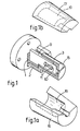
- the measuring member of the means comprises a fixed part 2 and a part 3 movable radially in relation to the latter.
- the fixed part 2 consists of a hollow shaft which is attached by bolts 4 to the support 1. From the fixed part 2, which is arranged horozintally during the measurement, a segment of 120° is removed at the top.
- This load meter 6 contains a bending bar 9, provided with a cage 8 of synthetic material, which has a specially shaped recess 10 that keeps the ends of the bending bar 9 from rotating in relation to one another when the bending bar 9 is loaded in vertical direction. Namely, under vertical load the bending bar 9 would exhibit double reverse symmetrical bending, owing to which the free end does not rotate in relation to the solidly fixed end.
- the movable part 3 of the measuring member consisting of an axial segment, is attached to the free end of the bending bar 9 by a bolt 13.
- a fitted pin 14 serves for accurate positioning of the movable part 3 in relation to the bending bar 9.
- the axial segments of the fixed part 2 and the movable part 3 are reground after their assembly, in order to obtain a very accurate circular shape of the two parts together.
- Between the fixed part 2 and the movable part 3 is made a slot 15, so that the movable part 3 is displaceable radially inward.
- auxiliary elements 16 and 17 On the fixed part 2 and the movable part 3 are mounted auxiliary elements 16 and 17, a cylindrical cavity 18 and 19 fitting very accurately on the outside of the fixed part 2 and the movable part 3.
- the auxiliary element 16 In its assembly and/or disassembly the auxiliary element 16 must be slipped respectively on or off the fixed part 2, the cross section of the cavity 18 there enclosing an angle of 240°.
- the assemblies 16, 17 of auxiliary elements always have a circular cross section of any desired size, but their shape in longitudinal direction may be freely selected. Consequently, it is possible to test sealing rings of every type and every size simply by replacing these assemblies 16, 17.
- the relation between the pressing force and the axial diameter of a single sealing ring may be determined by slipping the latter over the conical assembly 16,17 of auxiliary elements.
- Fig. 4 shows the means placed in a measuring arrangement, a sealing ring 22 being slipped onto the assembly 16, 17 of auxiliary elements.
- the sealing ring 22 is attached to a plate 23 designed with a hole, which plate is capable of being displaced by means of guide bushings 24 in longitudinal direction along guides 25.
- the guides 25 are attached by their end to a bracket 26, which in turn is connected with a rotary spindle 27.
- the axis of rotation of the spindle lies in line with the cardioid line ofthe sealing ring 22, so that the latter is capable of rotation about the assembly 16,17 of auxiliary members.
- the support 1 of the measuring means is supported by an opposing part of the arrangement, not further illustrated.
Landscapes
- Physics & Mathematics (AREA)
- General Physics & Mathematics (AREA)
- Force Measurement Appropriate To Specific Purposes (AREA)
- Measurement Of Force In General (AREA)
Description
- The invention relates to a means for measuring a radial force proportionally distributed over the circumference of a member having a circular cross section, in particular for measuring the pressing force of a sealing ring on a shaft at rotation, wherein a measuring member has a fixed part and a part movable radially in relation to the latter, which parts are coupled to a load meter comprising strain gauges or stretch strips.
- Such a means for measuring the pressing force of a sealing ring is known from the German Offenlegungsschriften A-2747.262 and A-2444.036. According to these known disclosures a displacement of a movable part of the measuring member, consisting of half cylinders, is transmitted to a load meter via a transmission mechnan- ism. The transmission mechanism consists of hinged angular elements, which convert the radial displacement of the movable part into an axial displacement that is measured by the load meter and reduced to a force. This angular element is only in loose contact with the movable part of the measuring member and with the load meter.
- A measuring means of the same type is also disclosed in the French patent 2408.126. However bending moments and torsion are obviously also introduced in the device when the sealing element by the axial adjusting element is moved along its support.
- A drawback of these known means in general is that the transmission mechanisms introduce errors into the measurements as a result of clearances and hysteresis in the transmission. This likewise influences the reproduceability of the measurements.
- The object of the present invention is to procure a means of the kind mentioned in which the drawbacks described above are eliminated in a simple but effective way.
- To this end, the means according to the invention is characterized in that said load meter consists of a bar one end of which is connected with a support and the other end is provided with said strain gauges, whereby around said bar the fixed and movable parts are arranged.
- In this measuring means all moving transmissions are omitted and load meter is connected directly with both parts of the measuring member. Clearances and hysteresis which may occur in a transmission mechanism and produce errors are consequently completely eliminated. By this means it is alternatively possible to measure the pressing force in sealing rings rotating very slowly (for example, one revolution per minute). This has the advantage that the static friction appearing in a stationary sealing ring and influencing the measurement is then no longer present.
- A favourable embodiment of the means according to the invention is characterized in that around said fixed and said movable parts on said bar auxiliary elements forming an assembly are arranged to accept said sealing member. Preferably the assembly of said auxiliary means are conical shaped. Therefore sealing rings having different diameters may be tested in a very simple but effective way by this means.
- In addition, it is proposed according to the invention that the movable part of the measuring member comprise a circular segment having an enclosed angle of about 120°.
- The advantage with respect to a movable part of the measuring member consisting of a half cylinder is a reduced disturbing influence on measurement of the pressing force in sealing rings rotating very slowly. Namely, a rotating sealing ring causes a dynamic frictional force in tangential direction. In a perfectly symmetrical design of the measuring member the resulting force in the direction of the load meter would be zero. In small deviation from the ideal situation, however, the greatest disturbing forces in the movable part consisting of a half cylinder would appear at the ends of a center line defining the said movable part. By reducing the enclosed angle of the segment forming the movable part, the regions where the greatest component of error could occur fall outside the region of measurement. The enclosed angle may not be selected too small, however, because local disturbing forces would then exert too great an influence on the total force, while the displacement of the movable part would likewise be capable of influencing the pressing force acting upon it.
- The invention will be explained below with the aid of the drawing, which represents an embodiment of the means according to the invention.
- Fig. 1 is a perspective view, represented schematically, of a cut-away means according to the invention. Fig. 1a and Fig. 1b showing auxiliary elements.
- Fig. 2 is a side view of the means of Fig. 1, with assembled auxiliary elements.
- Fig. 3 is a cross section along line III-III in Fig. 2.
- Fig. 4 is a side view of the device of Fig. 1 placed in a partially represented measuring arrangement.
- In the drawing is represented an example of a means according to the invention, which is supported by a
support 1. The measuring member of the means comprises afixed part 2 and apart 3 movable radially in relation to the latter. - The
fixed part 2 consists of a hollow shaft which is attached by bolts 4 to thesupport 1. From thefixed part 2, which is arranged horozintally during the measurement, a segment of 120° is removed at the top. - In a
groove 5 of the support 1 a load meter 6 is attached bybolts 7. This load meter 6 contains abending bar 9, provided with acage 8 of synthetic material, which has a speciallyshaped recess 10 that keeps the ends of thebending bar 9 from rotating in relation to one another when thebending bar 9 is loaded in vertical direction. Namely, under vertical load thebending bar 9 would exhibit double reverse symmetrical bending, owing to which the free end does not rotate in relation to the solidly fixed end. - In the two circular parts of the
recess 10 are symmetrically fitted pairs of coupledstretch strips 11, by which the vertical load on thebending bar 9 may be measured and on which moments acting on thebending bar 9 have no influence.Wiring 12 provides for the electrical connection of thestrips 11. - The
movable part 3 of the measuring member, consisting of an axial segment, is attached to the free end of thebending bar 9 by abolt 13. A fittedpin 14 serves for accurate positioning of themovable part 3 in relation to thebending bar 9. - The axial segments of the
fixed part 2 and themovable part 3 are reground after their assembly, in order to obtain a very accurate circular shape of the two parts together. Between thefixed part 2 and themovable part 3 is made aslot 15, so that themovable part 3 is displaceable radially inward. - On the
fixed part 2 and themovable part 3 are mountedauxiliary elements cylindrical cavity fixed part 2 and themovable part 3. In its assembly and/or disassembly theauxiliary element 16 must be slipped respectively on or off thefixed part 2, the cross section of thecavity 18 there enclosing an angle of 240°. A plurality ofbolts auxiliary elements fixed part 2 and themovable part 3, respectively. - The
assemblies assemblies - In addition, with a slightly conical shape of the
assembly conical assembly - Fig. 4 shows the means placed in a measuring arrangement, a
sealing ring 22 being slipped onto theassembly sealing ring 22 is attached to aplate 23 designed with a hole, which plate is capable of being displaced by means ofguide bushings 24 in longitudinal direction alongguides 25. Theguides 25 are attached by their end to abracket 26, which in turn is connected with arotary spindle 27. The axis of rotation of the spindle lies in line with the cardioid line ofthesealing ring 22, so that the latter is capable of rotation about theassembly - The
support 1 of the measuring means is supported by an opposing part of the arrangement, not further illustrated. - The invention is not limited to the example illustrated in the drawing which may be varied in different ways within the scope of the invention.
Claims (5)
Applications Claiming Priority (2)
| Application Number | Priority Date | Filing Date | Title |
|---|---|---|---|
| NL8403570 | 1984-11-23 | ||
| NL8403570A NL8403570A (en) | 1984-11-23 | 1984-11-23 | DEVICE FOR MEASURING A RADIAL FORCE. |
Publications (2)
| Publication Number | Publication Date |
|---|---|
| EP0182438A1 EP0182438A1 (en) | 1986-05-28 |
| EP0182438B1 true EP0182438B1 (en) | 1990-01-03 |
Family
ID=19844808
Family Applications (1)
| Application Number | Title | Priority Date | Filing Date |
|---|---|---|---|
| EP85201882A Expired EP0182438B1 (en) | 1984-11-23 | 1985-11-15 | Means for measuring a radial force |
Country Status (5)
| Country | Link |
|---|---|
| US (1) | US4703662A (en) |
| EP (1) | EP0182438B1 (en) |
| JP (1) | JPS61130838A (en) |
| DE (1) | DE3575202D1 (en) |
| NL (1) | NL8403570A (en) |
Cited By (1)
| Publication number | Priority date | Publication date | Assignee | Title |
|---|---|---|---|---|
| KR101965412B1 (en) * | 2018-02-12 | 2019-04-03 | 아이가드 주식회사 | Tension Sensing Type Detection System |
Families Citing this family (11)
| Publication number | Priority date | Publication date | Assignee | Title |
|---|---|---|---|---|
| JPH03201920A (en) * | 1989-12-28 | 1991-09-03 | Yoshida Erushisu Kk | Chicken raising in chicken barn |
| DE4310509C2 (en) * | 1993-03-31 | 1995-05-24 | Freudenberg Carl Fa | Process for measuring the radial force of a sealing ring |
| US5365797A (en) * | 1994-01-07 | 1994-11-22 | Mccrory Iii Claud O | Device for measuring the amount of force applied to a cable |
| RU2010142965A (en) | 2008-04-17 | 2012-05-27 | Синкрони, Инк. (US) | HIGH SPEED MOTOR WITH PERMANENT MAGNET AND GENERATOR WITH METAL ROTOR WITH LOW LEVEL |
| CA2721818A1 (en) | 2008-04-18 | 2009-11-19 | Synchrony, Inc. | Magnetic thrust bearing with integrated electronics |
| US9583991B2 (en) | 2009-06-24 | 2017-02-28 | Synchrony, Inc. | Systems, devices, and/or methods for managing magnetic bearings |
| US8987959B2 (en) | 2010-06-23 | 2015-03-24 | Dresser-Rand Company | Split magnetic thrust bearing |
| DE102012206655B4 (en) | 2012-04-23 | 2018-09-06 | Aktiebolaget Skf | Method for determining the radial prestressing force between a sealing element and a component to be sealed and measuring element therefor |
| CN106969865B (en) * | 2017-02-22 | 2023-04-21 | 浙江万向精工有限公司 | Sealing ring side lip pressure measuring device and measuring method |
| CN108151942A (en) * | 2018-01-30 | 2018-06-12 | 湖州职业技术学院 | A kind of sealing ring radial load testboard |
| CN119147135B (en) * | 2024-11-21 | 2025-04-15 | 人本股份有限公司 | Rubber seal lip contact force testing equipment for wheel hub bearings |
Family Cites Families (8)
| Publication number | Priority date | Publication date | Assignee | Title |
|---|---|---|---|---|
| US1698200A (en) * | 1926-05-16 | 1929-01-08 | Zh Rikagaku Kenkyujo | Apparatus for measuring pressure of piston rings |
| US2866059A (en) * | 1956-06-01 | 1958-12-23 | Baldwin Lima Hamilton Corp | Slotted type multiple bending beam |
| FR1373623A (en) * | 1962-11-20 | 1964-09-25 | Goetzewerke | Device for measuring the radial elasticity of shaft sealing rings |
| DE1573500B2 (en) * | 1966-01-31 | 1971-11-25 | Fa Carl Freudenberg, 6940 Weinheim | DEVICE FOR MEASURING RADIAL FORCES IN SEALING ELEMENTS MADE OF RUBBER-ELASTIC MATERIAL AND IN SPRING ELEMENTS |
| US3488682A (en) * | 1967-05-17 | 1970-01-06 | Timken Roller Bearing Co | Bearing seal lip measuring apparatus |
| DE2444036A1 (en) * | 1974-09-14 | 1976-03-25 | Volkswagenwerk Ag | Shaft sealing ring testing device - measures inwardly directed radial force by longitudinally split mandrel for ring stretching |
| DE2747262C3 (en) * | 1977-10-21 | 1980-05-14 | Kaco Gmbh + Co, 7100 Heilbronn | Device for measuring radial forces |
| DE2748945A1 (en) * | 1977-11-02 | 1979-05-03 | Lechler Elring Dichtungswerke | DEVICE FOR MEASURING RADIAL FORCES IN ELASTIC, RING-SHAPED MACHINE ELEMENTS, IN PARTICULAR RADIAL SHAFT SEALING RINGS |
-
1984
- 1984-11-23 NL NL8403570A patent/NL8403570A/en not_active Application Discontinuation
-
1985
- 1985-11-13 US US06/797,700 patent/US4703662A/en not_active Expired - Fee Related
- 1985-11-15 EP EP85201882A patent/EP0182438B1/en not_active Expired
- 1985-11-15 DE DE8585201882T patent/DE3575202D1/en not_active Expired - Lifetime
- 1985-11-22 JP JP60261589A patent/JPS61130838A/en active Pending
Cited By (1)
| Publication number | Priority date | Publication date | Assignee | Title |
|---|---|---|---|---|
| KR101965412B1 (en) * | 2018-02-12 | 2019-04-03 | 아이가드 주식회사 | Tension Sensing Type Detection System |
Also Published As
| Publication number | Publication date |
|---|---|
| EP0182438A1 (en) | 1986-05-28 |
| JPS61130838A (en) | 1986-06-18 |
| NL8403570A (en) | 1986-06-16 |
| DE3575202D1 (en) | 1990-02-08 |
| US4703662A (en) | 1987-11-03 |
Similar Documents
| Publication | Publication Date | Title |
|---|---|---|
| US4703662A (en) | Means for measuring a radial force | |
| US4035044A (en) | Bearing assembly | |
| DE3612038A1 (en) | METHOD AND DEVICE FOR MEASURING TENSITY AND ELASTICITY FORCES | |
| DK1644706T3 (en) | Cross Spring element | |
| US4517843A (en) | Material and component testing machine | |
| JPS586882B2 (en) | extensometer | |
| US4077130A (en) | Apparatus for measuring the taper and the out-of-roundness of a revolutionary surface of a workpiece | |
| WO2004008076A1 (en) | Scale reading apparatus | |
| GB2130384A (en) | Force-measuring device | |
| US4393698A (en) | Device for measuring hollow cylinder surfaces | |
| US3969933A (en) | Spring joint for measuring device | |
| KR930000483B1 (en) | Rotary encoder | |
| GB2052078A (en) | Load Cell | |
| US4965926A (en) | Tensioning assembly apparatus having transducers mounted on the projections for tensioned retaining rings | |
| GB2168498A (en) | Thrust measuring devices | |
| US3431775A (en) | Resilient body for dynamometer | |
| JPH0648188Y2 (en) | Overload clutch trip torque setting mechanism | |
| US4556346A (en) | Drill press mounting apparatus for balancing machine | |
| SU800771A1 (en) | Stand for calibrating antifriction bearings | |
| SU1532831A1 (en) | Device for measuring rotation resistance torque of large heavily loaded rolling-contact bearing | |
| SU436250A1 (en) | DYNAMOMETER FOR MEASURING THE CLAMPING EFFICIENCY | |
| SU1201693A1 (en) | Optical transducer | |
| SU838434A1 (en) | Dynamometer | |
| CN116046381B (en) | Method and device for accurately positioning surrounding shafting | |
| SU1103672A1 (en) | Device for checking gas-dynamic tab support |
Legal Events
| Date | Code | Title | Description |
|---|---|---|---|
| PUAI | Public reference made under article 153(3) epc to a published international application that has entered the european phase |
Free format text: ORIGINAL CODE: 0009012 |
|
| AK | Designated contracting states |
Kind code of ref document: A1 Designated state(s): DE FR GB IT NL SE |
|
| 17P | Request for examination filed |
Effective date: 19861021 |
|
| 17Q | First examination report despatched |
Effective date: 19880304 |
|
| GRAA | (expected) grant |
Free format text: ORIGINAL CODE: 0009210 |
|
| AK | Designated contracting states |
Kind code of ref document: B1 Designated state(s): DE FR GB IT NL SE |
|
| REF | Corresponds to: |
Ref document number: 3575202 Country of ref document: DE Date of ref document: 19900208 |
|
| ET | Fr: translation filed | ||
| ITF | It: translation for a ep patent filed | ||
| PLBE | No opposition filed within time limit |
Free format text: ORIGINAL CODE: 0009261 |
|
| STAA | Information on the status of an ep patent application or granted ep patent |
Free format text: STATUS: NO OPPOSITION FILED WITHIN TIME LIMIT |
|
| 26N | No opposition filed | ||
| ITTA | It: last paid annual fee | ||
| PGFP | Annual fee paid to national office [announced via postgrant information from national office to epo] |
Ref country code: GB Payment date: 19921103 Year of fee payment: 8 |
|
| PGFP | Annual fee paid to national office [announced via postgrant information from national office to epo] |
Ref country code: FR Payment date: 19921109 Year of fee payment: 8 |
|
| PGFP | Annual fee paid to national office [announced via postgrant information from national office to epo] |
Ref country code: SE Payment date: 19921116 Year of fee payment: 8 |
|
| PGFP | Annual fee paid to national office [announced via postgrant information from national office to epo] |
Ref country code: DE Payment date: 19921123 Year of fee payment: 8 |
|
| PGFP | Annual fee paid to national office [announced via postgrant information from national office to epo] |
Ref country code: NL Payment date: 19921130 Year of fee payment: 8 |
|
| PG25 | Lapsed in a contracting state [announced via postgrant information from national office to epo] |
Ref country code: GB Effective date: 19931115 |
|
| PG25 | Lapsed in a contracting state [announced via postgrant information from national office to epo] |
Ref country code: SE Effective date: 19931116 |
|
| PG25 | Lapsed in a contracting state [announced via postgrant information from national office to epo] |
Ref country code: NL Effective date: 19940601 |
|
| GBPC | Gb: european patent ceased through non-payment of renewal fee |
Effective date: 19931115 |
|
| NLV4 | Nl: lapsed or anulled due to non-payment of the annual fee | ||
| PG25 | Lapsed in a contracting state [announced via postgrant information from national office to epo] |
Ref country code: FR Effective date: 19940729 |
|
| PG25 | Lapsed in a contracting state [announced via postgrant information from national office to epo] |
Ref country code: DE Effective date: 19940802 |
|
| REG | Reference to a national code |
Ref country code: FR Ref legal event code: ST |
|
| EUG | Se: european patent has lapsed |
Ref document number: 85201882.9 Effective date: 19940610 |