EP0181808B1 - Spectrum analyser using surface wave dispersion filters - Google Patents
Spectrum analyser using surface wave dispersion filters Download PDFInfo
- Publication number
- EP0181808B1 EP0181808B1 EP85402074A EP85402074A EP0181808B1 EP 0181808 B1 EP0181808 B1 EP 0181808B1 EP 85402074 A EP85402074 A EP 85402074A EP 85402074 A EP85402074 A EP 85402074A EP 0181808 B1 EP0181808 B1 EP 0181808B1
- Authority
- EP
- European Patent Office
- Prior art keywords
- signal
- premultiplication
- dispersive
- convolution
- filters
- Prior art date
- Legal status (The legal status is an assumption and is not a legal conclusion. Google has not performed a legal analysis and makes no representation as to the accuracy of the status listed.)
- Expired
Links
Images

Classifications
-
- G—PHYSICS
- G01—MEASURING; TESTING
- G01R—MEASURING ELECTRIC VARIABLES; MEASURING MAGNETIC VARIABLES
- G01R23/00—Arrangements for measuring frequencies; Arrangements for analysing frequency spectra
- G01R23/16—Spectrum analysis; Fourier analysis
- G01R23/165—Spectrum analysis; Fourier analysis using filters
Definitions
- the present invention relates to a spectrum analyzer with dispersive surface wave filters.
- MCM Multiplication-Convolution-Multiplication
- the premultiplication ramp Ri (t) is obtained by attacking a first dispersive filter, called the premultiplication filter, by a Dirac 8 1 pulse (t).
- the postmultiplication ramp R 2 (t) is obtained by attacking a second dispersive filter, called the postmultiplication filter, by a Dirac 8 2 pulse (t) which is triggered with a delay T relative to the pulse 8 1 (t).
- convolution with the ramp R (t) is obtained by passing through a dispersive filter, called convolution filter, having for impulse response R (t).
- a spectrum analyzer of this type is described in particular in Communication IX.4 by C. LARDAT, entitled “Spectrum analyzers using dispersive surface wave filters”, in the International Collogue on Radar of 1978 (p. 303 to 311 ).
- phase measurement is marred by an error term which depends on the variations of the characteristics of the dispersive filters with the temperature and of the synchronization defects of the pulse 8 2 (t) with respect to the pulse 8 1 (t ).
- the trigger delay of the pulse 8 2 (t) relative to the pulse 8 1 (t) is not strictly equal to T, it is no longer accurate to say that the measurement instant phase is the instant t 2 - (T / 2), and the phase measurement is then distorted.
- phase measurement is falsified when the temperature varies because, the parameters of the dispersive lines varying, the delay in triggering of the pulse 8 2 (t) relative to the pulse 8 1 (t) n is more strictly equal to T.
- One possibility of minimizing these faults would be to attack their cause by stabilizing the temperature of the analyzer, but this solution is generally not possible for reasons of volume and consumption; moreover it leaves the problem of errors due to the lack of synchronization of the pulses ⁇ 2 (t) and 8 1 (t) intact.
- the subject of the present invention is a structure making it possible to avoid phase defects linked to tripping errors of the dispersive premultiplication and postmultiplication filters and to the drift of the temperature dispersive filters, not by preventing these defects from occurring, but by compensating them exactly by identical faults generated by an identical spectrum analyzer placed under the same conditions and analyzing a reference signal which is in particular a Dirac 8 (t) pulse.
- the spectrum analyzer with dispersive surface wave filters according to the invention comprising a first assembly with structure “MCM”, that is to say in which premultiplication operations are carried out successively, convolution and postmultiplication, respectively of the signal to be analyzed, of the signal obtained at the end of the premultiplication and of the signal obtained at the end of the convolution, by a first, a second and a third ramp modulated linearly in frequency, this first set receiving the signal to be analyzed, and these frequency ramps being constituted by the impulse response of dispersive filters, respectively called premultiplication, convolution and postmultiplication filters, is characterized in that it further comprises, on the one hand a second assembly with “MCM” structure identical to the first and receiving a reference signal, the dispersive filters of premultiplication and postmultiplicat respectively ion of the first and second sets respectively receiving the same control signal, on the other hand a mixer receiving the output signals of the first and second sets, and providing the output signal of the spectrum analyzer.
- the present invention also relates to a simplification of this latter structure consisting in the pooling of the dispersive premultiplication filter of the two analyzers (according to claim 3), and / or in the removal of the dispersive postmultiplication filter of the two analyzers (according to claim 4).
- the spectrum analyzer according to the known art represented in FIG. 1 comprises a mixer 1 which performs the premultiplication of a signal to be analyzed f (t) by a ramp Ri (t) linearly modulated in frequency obtained at the output of a dispersive surface wave filter 2, of band B and of duration T, attacked by a Dirac pulse 8, (t).
- This analyzer also includes a dispersive surface wave filter 3, of band 2B, of duration 2T, and of slope opposite to R, (t), at the input of which the output signal of mixer 1 is applied, and which performs the convolution of this signal by a ramp R (t) modulated linearly in frequency, the ramp R (t) corresponding to the impulse response of the dispersive filter 3.
- This analyzer finally comprises a mixer 4 which performs the postmultiplication of the output signal of the filter dispersive 3 by a ramp R 2 (t) linearly frequency modulated, obtained at the output of a dispersive filter with surface waves 5, of band B and of duration T, attacked by a Dirac 8 2 (t) pulse.
- the output signal s (t) of this spectrum analyzer is obtained at the output of mixer 4.
- the dispersive filter 3 is a dispersive filter of band 2B and of duration 2T. His impulse response is:
- This filter can be taken with the same slope as the dispersive filter 2, and in this case it is necessary to add up the phases, or else with the same slope as the dispersive filter 3 and in this case it is necessary to make the difference in phases.
- the output signal valid for t between T / 2 and 3T / 2.
- the output signal from the spectrum analyzer becomes:
- the first corresponds to an error term affecting the measurement of the phase.
- the spectrum analyzer according to the invention shown in FIG. 2 makes it possible to dispense with this error term.
- This analyzer has a differential structure obtained by means of a first spectrum analyzer 6 identical to that of FIG. 1, receiving on its input the signal to be analyzed f (t), and of a second spectrum analyzer. 7 identical to spectrum analyzer 6, but receiving on its input a Dirac 8 (t) pulse, also called reference signal.
- the spectrum analyzer 7 comprises, like the analyzer 6, two mixers 8 and 11, and three dispersive filters 9, 10 and 12.
- the Dirac pulses ⁇ 1 (t) and 8 2 (t) are common to the two analyzers and the output signal s (t) is obtained at the output of a mixer 13 which receives on the one hand the output signal of the first analyzer 6, on the other hand the output signal of the second analyzer 7.
- phase error term highlighted above is differentially canceled. It is noted that any input signal from the analyzer 7 makes it possible to obtain this result. However, since there are only the differences between the spectrum of the signal to be analyzed f (t) and the spectrum of the input signal of the analyzer 7 which remain at the output of the mixer 13, it is preferable to use a Dirac pulse 8 (t) because the spectrum of a sufficiently narrow Dirac pulse is constant in modulus and has a zero phase.
- the embodiment of the spectrum analyzer shown in Figure 3 differs from that shown in Figure 2 in that the dispersive modulation filters 2 and 9 are replaced by a single modulation filter 14 and in that the dispersive filters demodulation 5 and 12, as well as the mixers 4 and 11 associated with them are deleted.
Description
La présente invention concerne un analyseur de spectre à filtres dispersifs à ondes de surface.The present invention relates to a spectrum analyzer with dispersive surface wave filters.
Les analyseurs de spectre en temps réel ont connu d'importants développements au cours de ces dernières années et on distingue soit des systèmes entièrement numériques, soit des systèmes utilisant des techniques analogiques, tels que les analyseurs à filtres dispersifs à ondes de surface auxquels se rapporte la présente invention. Ces derniers utilisent par exemple une structure dite « M-C-M » (Multiplication-Convolution-Multiplication), grâce à laquelle le spectre d'un signal à analyser est obtenu en prémultipliant ce signal par une première rampe R1(t) modulée linéairement en fréquence, de bande B et de durée T, en effectuant ensuite la convolution du signal ainsi obtenu avec une deuxième rampe R(t) modulée linéairement en fréquence, de bande 2B et de durée 2T, et de pente opposée à Rl(t), et en postmultipliant le signal ainsi obtenu par une troisième rampe R2(t) modulée linéairement en fréquence, de bande B et de durée T, et de pente identique à Ri(t).Real-time spectrum analyzers have undergone significant developments in recent years and there are either fully digital systems or systems using analog techniques, such as the surface wave dispersive filter analyzers to which the present invention. These latter use, for example, a structure called “MCM” (Multiplication-Convolution-Multiplication), thanks to which the spectrum of a signal to be analyzed is obtained by premultiplying this signal by a first ramp R 1 (t) linearly frequency modulated, of band B and of duration T, then carrying out the convolution of the signal thus obtained with a second ramp R (t) linearly modulated in frequency, of band 2B and of duration 2T, and of slope opposite to R l (t), and by postmultiplying the signal thus obtained by a third ramp R 2 (t) linearly modulated in frequency, of band B and of duration T, and of slope identical to Ri (t).
Ces rampes de fréquences sont avantageusement obtenues à partir de la réponse impulsionnelle de filtres dispersifs à ondes de surface.These frequency ramps are advantageously obtained from the impulse response of dispersive surface wave filters.
Ainsi la rampe de prémultiplication Ri(t) est obtenue en attaquant un premier filtre dispersif, dit filtre de prémultiplication, par une impulsion de Dirac 81(t). De même la rampe de postmultiplication R2(t) est obtenue en attaquant un deuxième filtre dispersif, dit filtre de postmultiplication, par une impulsion de Dirac 82(t) qui est déclenchée avec un retard T par rapport à l'impulsion 81(t). Enfin la convolution avec la rampe R(t) est obtenue par passage dans un filtre dispersif, dit filtre de convolution, ayant pour réponse impulsionnelle R(t).Thus the premultiplication ramp Ri (t) is obtained by attacking a first dispersive filter, called the premultiplication filter, by a Dirac 8 1 pulse (t). Similarly, the postmultiplication ramp R 2 (t) is obtained by attacking a second dispersive filter, called the postmultiplication filter, by a
Un analyseur de spectre de ce type est notamment décrit dans la communication IX.4 de C. LARDAT, intitulée « Analyseurs de spectre utilisant des filtres dispersifs à ondes de surface », au Collogue International sur le Radar de 1978 (p. 303 à 311).A spectrum analyzer of this type is described in particular in Communication IX.4 by C. LARDAT, entitled “Spectrum analyzers using dispersive surface wave filters”, in the International Collogue on Radar of 1978 (p. 303 to 311 ).
Le signal obtenu en sortie de cet analyseur est une impulsion dont la position dans le temps est fonction de la fréquence F à analyser, et plus précisément égale à T + (F/k) (où K est la pente des rampes de fréquences, égale à B/T), dont l'amplitude est proportionnelle à l'amplitude de la raie du spectre du signal à analyser à la fréquence F, et dont la phase est la phase du signal à analyser, à l'instant t = 0. Cette phase est par ailleurs mesurée à un instant de référence t=t2-(T/2) où t2 est l'instant de déclenchement de l'impulsion de démodulation 82(t).The signal obtained at the output of this analyzer is a pulse whose position in time is a function of the frequency F to be analyzed, and more precisely equal to T + (F / k) (where K is the slope of the frequency ramps, equal at B / T), the amplitude of which is proportional to the amplitude of the line of the spectrum of the signal to be analyzed at frequency F, and the phase of which is the phase of the signal to be analyzed, at time t = 0. This phase is moreover measured at a reference instant t = t 2 - (T / 2) where t 2 is the instant of triggering of the demodulation pulse 8 2 (t).
En pratique, ces résultats ne sont toutefois pas vérifiés avec exactitude ; notamment la mesure de phase est entachée d'un terme d'erreur qui dépend des variations des caractéristiques des filtres dispersifs avec la température et des défauts de synchronisation de l'impulsion 82(t) par rapport à l'impulsion 81(t). En effet lorsque le retard de déclenchement de l'impulsion 82(t) par rapport à l'impulsion 81(t) n'est pas rigoureusement égal à T, il n'est plus exact de dire que l'instant de mesure de phase est l'instant t2―(T/2), et la mesure de phase se trouve alors faussée. Pour les mêmes raisons, la mesure de phase se trouve faussée lorsque la température varie car, les paramètres des lignes dispersives variant, le retard de déclenchement de l'impulsion 82(t) par rapport à l'impulsion 81(t) n'est plus rigoureusement égal à T. Une possibilité de minimiser ces défauts serait de s'attaquer à leur cause en stabilisant en température l'analyseur, mais cette solution n'est généralement pas possible pour des raisons de volume et de consommation ; de plus elle laisse entier le problème des erreurs dues au défaut de synchronisation des impulsions δ2(t) et 81(t).In practice, however, these results are not verified with accuracy; in particular the phase measurement is marred by an error term which depends on the variations of the characteristics of the dispersive filters with the temperature and of the synchronization defects of the pulse 8 2 (t) with respect to the pulse 8 1 (t ). Indeed, when the trigger delay of the pulse 8 2 (t) relative to the pulse 8 1 (t) is not strictly equal to T, it is no longer accurate to say that the measurement instant phase is the instant t 2 - (T / 2), and the phase measurement is then distorted. For the same reasons, the phase measurement is falsified when the temperature varies because, the parameters of the dispersive lines varying, the delay in triggering of the pulse 8 2 (t) relative to the pulse 8 1 (t) n is more strictly equal to T. One possibility of minimizing these faults would be to attack their cause by stabilizing the temperature of the analyzer, but this solution is generally not possible for reasons of volume and consumption; moreover it leaves the problem of errors due to the lack of synchronization of the pulses δ 2 (t) and 8 1 (t) intact.
La présente invention a pour objet une structure permettant d'éviter les défauts de phase liés aux erreurs de déclenchement des filtres dispersifs de prémultiplication et de postmultiplication et aux dérives des filtres dispersifs en température, non pas en évitant que ces défauts se produisent, mais en les compensant exactement par des défauts identiques générés par un analyseur de spectre identique placé dans les mêmes conditions et analysant un signal de référence qui est notamment une impulsion de Dirac 8(t).The subject of the present invention is a structure making it possible to avoid phase defects linked to tripping errors of the dispersive premultiplication and postmultiplication filters and to the drift of the temperature dispersive filters, not by preventing these defects from occurring, but by compensating them exactly by identical faults generated by an identical spectrum analyzer placed under the same conditions and analyzing a reference signal which is in particular a Dirac 8 (t) pulse.
L'analyseur de spectre à filtres dispersifs à ondes de surface suivant l'invention (selon la revendication 1), comportant un premier ensemble à structure « M-C-M », c'est-à-dire dans lequel sont effectuées successivement des opérations de prémultiplication, convolution et postmultiplication, respectivement du signal à analyser, du signal obtenu à l'issue de la prémultiplication et du signal obtenu à l'issue de la convolution, par une première, une deuxième et une troisième rampe modulées linéairement en fréquence, ce premier ensemble recevant le signal à analyser, et ces rampes de fréquences étant constituées par la réponse impulsionnelle de filtres dispersifs, respectivement appelés filtres de prémultiplication, de convolution et de postmultiplication, est caractérisé en ce qu'il comporte en outre, d'une part un second ensemble à structure « M-C-M » identique au premier et recevant un signal de référence, les filtres dispersifs respectivement de prémultiplication et de postmultiplication du premier et du second ensembles recevant respectivement le même signal de commande, d'autre part un mélangeur recevant les signaux de sortie du premier et du second ensembles, et fournissant le signal de sortie de l'analyseur de spectre.The spectrum analyzer with dispersive surface wave filters according to the invention (according to claim 1), comprising a first assembly with structure “MCM”, that is to say in which premultiplication operations are carried out successively, convolution and postmultiplication, respectively of the signal to be analyzed, of the signal obtained at the end of the premultiplication and of the signal obtained at the end of the convolution, by a first, a second and a third ramp modulated linearly in frequency, this first set receiving the signal to be analyzed, and these frequency ramps being constituted by the impulse response of dispersive filters, respectively called premultiplication, convolution and postmultiplication filters, is characterized in that it further comprises, on the one hand a second assembly with “MCM” structure identical to the first and receiving a reference signal, the dispersive filters of premultiplication and postmultiplicat respectively ion of the first and second sets respectively receiving the same control signal, on the other hand a mixer receiving the output signals of the first and second sets, and providing the output signal of the spectrum analyzer.
La présente invention a également pour objet une simplification de cette dernière structure consistant dans la mise en commun du filtre dispersif de prémultiplication des deux analyseurs (selon la revendication 3), et/ou dans la suppression du filtre dispersif de postmultiplication des deux analyseurs (selon la revendication 4).The present invention also relates to a simplification of this latter structure consisting in the pooling of the dispersive premultiplication filter of the two analyzers (according to claim 3), and / or in the removal of the dispersive postmultiplication filter of the two analyzers (according to claim 4).
L'invention sera mieux comprise au moyen de la description qui suit et des figures annexées parmi lesquelles :
- la figure 1 est un schéma d'un analyseur de spectre suivant l'art connu ;
- la figure 2 est un premier chéma d'un analyseur de spectre suivant l'invention ;
- la figure 3 est un second schéma d'un analyseur de spectre suivant l'invention.
- Figure 1 is a diagram of a spectrum analyzer according to the known art;
- Figure 2 is a first diagram of a spectrum analyzer according to the invention;
- Figure 3 is a second diagram of a spectrum analyzer according to the invention.
Les éléments communs à ces différentes figures portent les mêmes références.The elements common to these different figures have the same references.
L'analyseur de spectre suivant l'art connu représenté sur la figure 1 comporte un mélangeur 1 qui effectue la prémultiplication d'un signal à analyser f(t) par une rampe Ri(t) modulée linéairement en fréquence obtenue en sortie d'un filtre dispersif à ondes de surface 2, de bande B et de durée T, attaqué par une impulsion de Dirac 8,(t). Cet analyseur comporte également un filtre dispersif à ondes de surface 3, de bande 2B, de durée 2T, et de pente opposée à R,(t), à l'entrée duquel est appliqué le signal de sortie du mélangeur 1, et qui effectue la convolution de ce signal par une rampe R(t) modulée linéairement en fréquence, la rampe R(t) correspondant à la réponse impulsionnelle du filtre dispersif 3. Cet analyseur comporte enfin un mélangeur 4 qui effectue la postmultiplication du signal de sortie du filtre dispersif 3 par une rampe R2(t) modulée linéairement en fréquence, obtenue en sortie d'un filtre dispersif à ondes de surface 5, de bande B et de durée T, attaqué par une impulsion de Dirac 82(t). Le signal de sortie s(t) de cet analyseur de spectre est obtenu en sortie du mélangeur 4.The spectrum analyzer according to the known art represented in FIG. 1 comprises a mixer 1 which performs the premultiplication of a signal to be analyzed f (t) by a ramp Ri (t) linearly modulated in frequency obtained at the output of a dispersive
On rappelle le fonctionnement de l'analyseur de spectre représenté sur la figure 1.We recall the operation of the spectrum analyzer shown in Figure 1.
Le filtre dispersif 2 est un filtre dispersif de bande B et de durée T. On suppose qu'il est déclenché à l'instant t = + (T/2). L'équation du signal obtenu en sortie est alors :![]()
![]()
![]()
![]()
![]()
![]()
![]()
![]()
Le filtre dispersif 3 est un filtre dispersif de bande 2B et de durée 2T. Sa réponse impulsionnelle est :
En sortie du filtre dispersif 3 on obtient le signal suivant
![]()
![]()
Ainsi :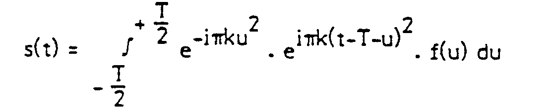


On peut calculer s(t) pour un signal à analyser f(t) de la forme :![]()
![]()
On obtient :

Ce filtre peut être pris de même pente que le filtre dispersif 2, et dans ce cas il faut faire la somme des phases, ou bien de même pente que le filtre dispersif 3 et dans ce cas il faut faire la différence des phases. Ainsi on aboutit au signal de sortie :![]()
![]()
Il s'agit d'une impulsion ayant les caractéristiques suivantes :
- -sa position dans le temps est T + (f/k), elle est donc fonction de la fréquence à analyser. Les bornes T/2 et 3T/2 correspondent aux fréquences f = - (B/2) et f = + B/2 ;
- -son amplitude est proportionnelle à l'amplitude de la raie de la fréquence d'entrée (dans le lobe principal) ;
- -sa phase est la phase du signal à analyser à l'instant t = 0 (tout au moins dans le lobe principal du sinus cardinal). En fait, cette phase est mesurée à un instant de référence t = t2 - (T/2) où t2 est l'instant de déclenchement de l'impulsion de démodulation 82(t) (si le système est calibré, notamment en température, on a t2 = T/2).
- -its position in time is T + (f / k), it is therefore a function of the frequency to be analyzed. The terminals T / 2 and 3T / 2 correspond to the frequencies f = - (B / 2) and f = + B / 2;
- -its amplitude is proportional to the amplitude of the line of the input frequency (in the main lobe);
- its phase is the phase of the signal to be analyzed at time t = 0 (at least in the main lobe of the cardinal sinus). In fact, this phase is measured at a reference instant t = t 2 - (T / 2) where t 2 is the instant of triggering of the demodulation pulse 8 2 (t) (if the system is calibrated, in particular in temperature, we have t 2 = T / 2).
Le schéma de la figure 1 réalise donc bien les fonctions d'un transformateur de Fourier. Cependant, comme on a va maintenant le montrer plus en détail, ces résultats se trouvent quelque peu faussés par l'influence de la température. Lorsque la température subit une variation △θ, on a en effet les modifications suivantes, en se limitant pour ce calcul à la seule variation du paramètre T :
- La pente k des filtres dispersifs devient : K' = B/T' avec T' = T + 2a (où 2a = C·Δθ· T).
- The slope k of the dispersive filters becomes: K '= B / T' with T '= T + 2a (where 2a = C · Δθ · T).
Le coefficient C est le coefficient de température des filtres dispersifs. Si ceux-ci sont réalisés sur un substrat au Niobate de Lythium, on a : C = ―10-4/°C.The coefficient C is the temperature coefficient of the dispersive filters. If these are made on a Lyobium Niobate substrate, we have: C = ―10 -4 / ° C.
A cette température, les équations des filtres dispersifs 2, 3 et 5 deviennent respectivement :

![]()
![]()
Pour un signal d'entrée f(t) de la forme :![]()
![]()
![]()
![]()
Le signal de sortie de l'analyseur de spectre devient :
![]()
![]()
Le signal de sortie de l'analyseur de spectre a donc été modifié :
- -la position dans le temps de l'impulsion a été décalée puisqu'elle est maintenant égale à T + 3a + (f/k') ;
- - on remarque la présence de termes de phase parasites :

- the position in time of the pulse has been shifted since it is now equal to T + 3a + (f / k ');
- - we notice the presence of parasitic phase terms:
Le deuxième terme n'est pas gênant car pour t = T + 3a + f/k', c'est-à-dire au sommet du lobe principal du sinus cardinal, il est nul. Par contre le premier correspond bien à un terme d'erreur affectant la mesure de la phase.The second term is not annoying because for t = T + 3a + f / k ', that is to say at the top of the main lobe of the cardinal sinus, it is zero. By cons the first corresponds to an error term affecting the measurement of the phase.
L'analyseur de spectre suivant l'invention représenté sur la figure 2 permet de s'affranchir de ce terme d'erreur. Cet analyseur a une structure différentielle obtenue au moyen d'un premier analyseur de spectre 6 identique à celui de la figure 1, recevant sur son entrée le signal à analyser f(t), et d'un second analyseur de spectre. 7 identique à l'analyseur de spectre 6, mais recevant sur son entrée une impulsion de Dirac 8(t), appelée aussi signal de référence. L'analyseur de spectre 7 comporte, comme l'analyseur 6, deux mélangeurs 8 et 11, et trois filtres dispersifs 9, 10 et 12. Les impulsions de Dirac δ1(t) et 82(t) sont communes aux deux analyseurs et le signal de sortie s(t) est obtenu en sortie d'un mélangeur 13 qui reçoit d'une part le signal de sortie du premier analyseur 6, d'autre part le signal de sortie du second analyseur 7.The spectrum analyzer according to the invention shown in FIG. 2 makes it possible to dispense with this error term. This analyzer has a differential structure obtained by means of a first spectrum analyzer 6 identical to that of FIG. 1, receiving on its input the signal to be analyzed f (t), and of a second spectrum analyzer. 7 identical to spectrum analyzer 6, but receiving on its input a Dirac 8 (t) pulse, also called reference signal. The
Avec une telle structure, le terme d'erreur de phase mis en évidence précédemment est différentielle- ment annulé. On remarque que n'importe quel signal d'entrée de l'analyseur 7 permet d'obtenir ce résultat. Cependant, comme il n'y a que les différences entre le spectre du signal à analyser f(t) et le spectre du signal d'entrée de l'analyseur 7 qui subsistent en sortie du mélangeur 13, il est préférable d'utiliser une impulsion de Dirac 8(t) car le spectre d'une impulsion de Dirac suffisamment étroite est constant en module et a une phase nulle.With such a structure, the phase error term highlighted above is differentially canceled. It is noted that any input signal from the
La forme de réalisation de l'analyseur de spectre représentée sur la figure 3 diffère de celle représentée sur la figure 2 en ce que les filtres dispersifs de modulation 2 et 9 sont remplacés par un seul filtre de modulation 14 et en ce que les filtres dispersifs de démodulation 5 et 12, ainsi que les mélangeurs 4 et 11 qui leur sont associés sont supprimés.The embodiment of the spectrum analyzer shown in Figure 3 differs from that shown in Figure 2 in that the
On montre maintenant qu'avec une telle structure, la mesure de phase n'est pas perturbée par des variations de température. Suivant le même raisonnement que précédemment, lorsque la température subit une variation △θ, on a en effet les modifications suivantes :
- La pente k des filtres dispersifs devient : k' = B'/T' avec B' = B + ΔB (où ΔB = ― C·△θ·B) et T' = T + 2a (où 2a = C·Δ·T).
- The slope k of the dispersive filters becomes: k '= B' / T 'with B' = B + ΔB (where ΔB = - C · △ θ · B) and T '= T + 2a (where 2a = C · Δ · T).
Le retard pur β des filtres dispersifs (dû essentiellement aux transducteurs) devient :![]()
![]()
Le coefficient C est le coefficient de température des filtres dispersifs. Si ceux-ci sont réalisés sur un substrat au Niobate de Lythium, on a : C =―10―4/°C.The coefficient C is the temperature coefficient of the dispersive filters. If these are made on a Lythium Niobate substrate, we have: C = ―10― 4 / ° C.
A température ambiante, on a les équations suivantes :
- - pour le filtre dispersif 14 de modulation, déclenché à t =―(T/2)―β :

- - pour le filtre dispersif 3 de convolution :

et 3. Lorsque la température subit une variation △θ, les fréquences fo et f1 deviennent respectivement f'o = fo + Afo et f'1 = f1 + △f1 avec Δfo = ―C·△θ·f0 et △f1 = ―C·△θ·f1.
- - for the
dispersive modulation filter 14, triggered at t = - (T / 2) ―β:
- - for the
dispersive filter 3 of convolution:filters
A cette température, les équations des filtres dispersifs de modulation 14 et de convolution 3 s'écrivent respectivement :
![]()
![]()
Par contre, à la différence du montage de la figure 1, le signal de démodulation est issu d'un filtre dispersif 10 de paramètres (2B, 2T) déclenché par une impulsion de Dirac centrée à l'instant t = 0 et mélangée au signal de modulation :
![]()

![]()
Pour un signal d'entrée f(t) de la forme :![]()
![]()
On obtient en sortie de l'analyseur de spectre :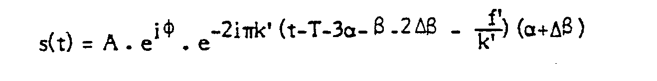

On remarque que pour l'instant t = T + 3α + (β + 2△β + (f'/k'), c'est-à-dire à l'instant du maximum de l'impulsion de sortie, la phase du signal s(t) est égale à la phase φ du signal à analyser. Par conséquent cette structure permet bien de s'affranchir des erreurs sur la mesure de la phase. Elle présente de plus, par rapport au montage de la figure 2, l'avantage d'être beaucoup plus simple à réaliser et à mettre en œuvre.We note that for the moment t = T + 3α + (β + 2 △ β + (f '/ k'), that is to say at the instant of the maximum of the output pulse, the phase of the signal s (t) is equal to the phase φ of the signal to be analyzed. Consequently, this structure makes it possible to overcome errors on the measurement of the phase. It also presents, compared to the assembly of FIG. 2, the advantage of being much simpler to carry out and to implement.
Avec le montage de la figure 2 comme avec celui de la figure 3, la phase du signal de sortie de l'analyseur de spectre est la phase du signal à analyser à l'instant t = 0. Cependant, contrairement au schéma de la figure 1, l'instant t = 0 correspond à une référence de temps constituée par le déclenchement de l'impulsion de référence 8(t).With the assembly of FIG. 2 as with that of FIG. 3, the phase of the output signal of the spectrum analyzer is the phase of the signal to be analyzed at time t = 0. However, unlike the diagram in the figure 1, the instant t = 0 corresponds to a time reference constituted by the triggering of the reference pulse 8 (t).
Claims (4)
Applications Claiming Priority (2)
| Application Number | Priority Date | Filing Date | Title |
|---|---|---|---|
| FR8416600 | 1984-10-30 | ||
| FR8416600A FR2572535B1 (en) | 1984-10-30 | 1984-10-30 | SPECTRUM ANALYZER WITH SURFACE WAVE DISPERSITIVE FILTERS |
Publications (2)
| Publication Number | Publication Date |
|---|---|
| EP0181808A1 EP0181808A1 (en) | 1986-05-21 |
| EP0181808B1 true EP0181808B1 (en) | 1989-04-26 |
Family
ID=9309150
Family Applications (1)
| Application Number | Title | Priority Date | Filing Date |
|---|---|---|---|
| EP85402074A Expired EP0181808B1 (en) | 1984-10-30 | 1985-10-25 | Spectrum analyser using surface wave dispersion filters |
Country Status (3)
| Country | Link |
|---|---|
| US (1) | US4716362A (en) |
| EP (1) | EP0181808B1 (en) |
| FR (1) | FR2572535B1 (en) |
Families Citing this family (7)
| Publication number | Priority date | Publication date | Assignee | Title |
|---|---|---|---|---|
| US4890055A (en) * | 1988-10-28 | 1989-12-26 | The Charles Stark Draper Laboratory, Inc. | Compensated chirp fourier transformer |
| WO1992018876A1 (en) * | 1991-04-18 | 1992-10-29 | Endress U. Hauser Gmbh U. Co. | Process and arrangement for retroreflective measurement of distance |
| US5818872A (en) * | 1996-12-31 | 1998-10-06 | Cirrus Logic, Inc. | Timing offset error extraction method and apparatus |
| US5937006A (en) * | 1997-05-28 | 1999-08-10 | The Aerospace Corporation | Frequency translating device transmission response method |
| US6265861B1 (en) * | 1997-10-20 | 2001-07-24 | Advantest Corp. | Frequency spectrum analyzer with high C/N ratio |
| FR2786908B1 (en) | 1998-12-04 | 2001-06-08 | Thomson Csf | PROCESS AND DEVICE FOR THE PROCESSING OF SOUNDS FOR THE HEARING DISEASE |
| US6362631B1 (en) * | 2000-04-25 | 2002-03-26 | Agilent Technologies, Inc. | Method for characterizing delay of frequency translation devices |
Family Cites Families (3)
| Publication number | Priority date | Publication date | Assignee | Title |
|---|---|---|---|---|
| US3900721A (en) * | 1974-02-14 | 1975-08-19 | Us Navy | Serial-access linear transform |
| US4282579A (en) * | 1979-10-22 | 1981-08-04 | The United States Of America As Represented By The Secretary Of The Navy | Discrete Fourier transform system using the dual chirp-Z transform |
| US4329651A (en) * | 1980-04-09 | 1982-05-11 | The United States Of America As Represented By The Secretary Of The Navy | Chirp filters/signals |
-
1984
- 1984-10-30 FR FR8416600A patent/FR2572535B1/en not_active Expired
-
1985
- 1985-10-21 US US06/789,952 patent/US4716362A/en not_active Expired - Fee Related
- 1985-10-25 EP EP85402074A patent/EP0181808B1/en not_active Expired
Also Published As
| Publication number | Publication date |
|---|---|
| EP0181808A1 (en) | 1986-05-21 |
| FR2572535B1 (en) | 1986-12-19 |
| US4716362A (en) | 1987-12-29 |
| FR2572535A1 (en) | 1986-05-02 |
Similar Documents
| Publication | Publication Date | Title |
|---|---|---|
| EP0219392A1 (en) | Shifting, non-recursive, discrete Fourier transform computing device, and its use in a radar system | |
| EP2535733B1 (en) | High-precision, compact altimetric measurement system | |
| EP0181808B1 (en) | Spectrum analyser using surface wave dispersion filters | |
| EP1982209A1 (en) | Frequency measuring broadband digital receiver | |
| EP2762912A1 (en) | Device and method for collecting data for locating a source of interference | |
| CA1323656C (en) | Method and meter for measuring the frequency of a periodical signal | |
| US5424631A (en) | Hybrid instantaneous frequency measurement compressive receiver apparatus and method | |
| EP1782536B1 (en) | Method of generating a digital signal that is representative of match errors in an analogue-to-digital conversion system with time interleaving, and an analogue-to-digital converter with time interleaving using same | |
| EP1940023A2 (en) | Bank of cascadable digital filters, and reception circuit including such a bank of cascaded filters | |
| EP0197801A2 (en) | Method and device for quickly setting the phase of a clock signal at a predetermined value | |
| EP1139115B1 (en) | Method and system for correcting QDM variations of a navigation system | |
| EP0390657B1 (en) | Measurement of the stability of transmission and reception in radar | |
| US20040189326A1 (en) | Vector-detecting apparatus and impedance measuring apparatus | |
| EP0226490B1 (en) | Synchronous switched-capacitor filter | |
| CA2006293C (en) | Non-intrusive transmission channel diagnostic device for a digital modem applied to a regenerative demodulator | |
| EP0796421B1 (en) | Filtering device particularly for a fuel gauge of a motor vehicle | |
| EP3605145A1 (en) | High-resolution remote processing method | |
| EP0055636B1 (en) | Off-boresight receiver for secondary radar | |
| EP0266832B1 (en) | Fully digital phase-locked loop | |
| US6952446B1 (en) | Digital filter bank followed by monobit receivers for signal processing | |
| EP0293287B1 (en) | Spread spectrum phase demodulator test system | |
| EP0740414A1 (en) | Programmable delay device for analog signals and corresponding programmable acoustic antenna | |
| EP0029760B1 (en) | Filter device and its use in radar display systems | |
| EP0012056B1 (en) | Telemetry device and use thereof in a tracking radar | |
| EP4220198A1 (en) | Method for adjusting an electric meter |
Legal Events
| Date | Code | Title | Description |
|---|---|---|---|
| PUAI | Public reference made under article 153(3) epc to a published international application that has entered the european phase |
Free format text: ORIGINAL CODE: 0009012 |
|
| AK | Designated contracting states |
Kind code of ref document: A1 Designated state(s): GB IT |
|
| 17P | Request for examination filed |
Effective date: 19860908 |
|
| 17Q | First examination report despatched |
Effective date: 19880818 |
|
| GRAA | (expected) grant |
Free format text: ORIGINAL CODE: 0009210 |
|
| AK | Designated contracting states |
Kind code of ref document: B1 Designated state(s): GB IT |
|
| ITF | It: translation for a ep patent filed |
Owner name: JACOBACCI & PERANI S.P.A. |
|
| RAP4 | Party data changed (patent owner data changed or rights of a patent transferred) |
Owner name: THOMSON-CSF |
|
| GBT | Gb: translation of ep patent filed (gb section 77(6)(a)/1977) | ||
| PLBE | No opposition filed within time limit |
Free format text: ORIGINAL CODE: 0009261 |
|
| STAA | Information on the status of an ep patent application or granted ep patent |
Free format text: STATUS: NO OPPOSITION FILED WITHIN TIME LIMIT |
|
| 26N | No opposition filed | ||
| PGFP | Annual fee paid to national office [announced via postgrant information from national office to epo] |
Ref country code: GB Payment date: 19910920 Year of fee payment: 7 |
|
| ITTA | It: last paid annual fee | ||
| PG25 | Lapsed in a contracting state [announced via postgrant information from national office to epo] |
Ref country code: GB Effective date: 19921025 |
|
| GBPC | Gb: european patent ceased through non-payment of renewal fee |
Effective date: 19921025 |