EP0181354B1 - Urine collector for incontinent women - Google Patents
Urine collector for incontinent women Download PDFInfo
- Publication number
- EP0181354B1 EP0181354B1 EP85901963A EP85901963A EP0181354B1 EP 0181354 B1 EP0181354 B1 EP 0181354B1 EP 85901963 A EP85901963 A EP 85901963A EP 85901963 A EP85901963 A EP 85901963A EP 0181354 B1 EP0181354 B1 EP 0181354B1
- Authority
- EP
- European Patent Office
- Prior art keywords
- urine
- collector
- urine collector
- section
- blank
- Prior art date
- Legal status (The legal status is an assumption and is not a legal conclusion. Google has not performed a legal analysis and makes no representation as to the accuracy of the status listed.)
- Expired
Links
- 210000002700 urine Anatomy 0.000 title claims abstract description 87
- 206010021639 Incontinence Diseases 0.000 title claims abstract description 8
- 230000002787 reinforcement Effects 0.000 claims description 4
- 241001313288 Labia Species 0.000 abstract description 19
- 239000013013 elastic material Substances 0.000 abstract 1
- 239000007788 liquid Substances 0.000 abstract 1
- 239000011324 bead Substances 0.000 description 12
- 210000003708 urethra Anatomy 0.000 description 8
- 210000001015 abdomen Anatomy 0.000 description 7
- 125000006850 spacer group Chemical group 0.000 description 6
- 210000001624 hip Anatomy 0.000 description 4
- 238000007789 sealing Methods 0.000 description 3
- 210000000689 upper leg Anatomy 0.000 description 3
- 210000003932 urinary bladder Anatomy 0.000 description 2
- 241000219357 Cactaceae Species 0.000 description 1
- 101100008046 Caenorhabditis elegans cut-2 gene Proteins 0.000 description 1
- 241001122767 Theaceae Species 0.000 description 1
- 210000000481 breast Anatomy 0.000 description 1
- 210000001217 buttock Anatomy 0.000 description 1
- 238000010276 construction Methods 0.000 description 1
- 210000003414 extremity Anatomy 0.000 description 1
- 210000002414 leg Anatomy 0.000 description 1
- 230000007774 longterm Effects 0.000 description 1
- 239000000463 material Substances 0.000 description 1
- 210000003205 muscle Anatomy 0.000 description 1
- 230000000149 penetrating effect Effects 0.000 description 1
- 210000003689 pubic bone Anatomy 0.000 description 1
- 210000005070 sphincter Anatomy 0.000 description 1
Images


Classifications
-
- A—HUMAN NECESSITIES
- A61—MEDICAL OR VETERINARY SCIENCE; HYGIENE
- A61F—FILTERS IMPLANTABLE INTO BLOOD VESSELS; PROSTHESES; DEVICES PROVIDING PATENCY TO, OR PREVENTING COLLAPSING OF, TUBULAR STRUCTURES OF THE BODY, e.g. STENTS; ORTHOPAEDIC, NURSING OR CONTRACEPTIVE DEVICES; FOMENTATION; TREATMENT OR PROTECTION OF EYES OR EARS; BANDAGES, DRESSINGS OR ABSORBENT PADS; FIRST-AID KITS
- A61F5/00—Orthopaedic methods or devices for non-surgical treatment of bones or joints; Nursing devices ; Anti-rape devices
- A61F5/44—Devices worn by the patient for reception of urine, faeces, catamenial or other discharge; Colostomy devices
- A61F5/451—Genital or anal receptacles
- A61F5/455—Genital or anal receptacles for collecting urine or discharge from female member
Definitions
- the present invention relates to a urine collector for incontinent women according to the preamble of claim 1.
- the urine collector known from US-A-3 194 238 with two elastically resilient sealing rings or beads is also unsatisfactory, since the urine which emerges from the urethra in an uncontrolled manner, particularly when it passes through the inner sealing ring, can also escape from its center the urine is drained into a collecting bag, gets out, leads to a feeling of being wet and, due to the lack of drainage in the collecting bag, escapes along the body.
- the present invention is therefore based on the object of proposing a urine collector for incontinent women which is simple to use, disturbs as little as possible when worn continuously and provides maximum safety in all situations and situations, i. H. Offers tightness.
- this object is achieved by a urine collector according to claim 1.
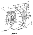
- the urine collector according to the invention is shown worn on a female abdomen in its position of use, parts of which are only visible in dashed lines because they are through one thigh of the woman, respectively. whose abdomen is covered.
- the following general parts of the urine collector according to the invention with the associated aids can be seen in this figure: the urine collector generally designated 1 and in particular its cut 2, the one with a waist belt 3 and a two-part auxiliary belt 4a, 4b in the correct position between the thighs 5a, 5b of the woman wearing the urine collector, respectively. at whose pubic 6 is held.
- a collector structure 11 located in the blank 2 is only indicated here.
- the urine collector 1 according to the invention is worn in a manner similar to a bikini bottom, the correct fit of the waist belt 3 and the auxiliary belt 4a, 4b essentially the correct position of the blank 2 with the collector arranged therein. Structure 11 secures.
- Fig. 2 the urine collector 1 is shown with all the aids in Fig. 1 from the back of the woman wearing it, essentially inevitably in broken lines.
- Fig. 3 it is shown in longitudinal section how the urine collector 1 according to the invention lies in the woman's crotch, the position of the collector structure 11 with respect to the urethral outlet 12 and the small and large labia 13 respectively. 14 is not clearly visible here. However, one can clearly see here how a front bead 15 seals the urine collector 1 against the pubic bone 16 against the front, whereas a rear bead 17 ensures the seal against the rear. This, in addition to the seal achieved by the collector structure 11 in cooperation with the labia 13,14. In addition, the border 18 running around the blank 2 serves as a further seal.
- the urine collector 1 according to the invention is kept as small as possible and only covers the absolutely necessary pubic area 6.
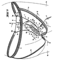
- Fig. 4 is shown in a perspective exploded view where the individual parts of the urine collector 1 according to the invention on the abdomen of the woman, respectively. whose shame 6 come to rest.
- FIG. 5 shows the urine collector 1 according to the invention in the worn position from the rear, the abdomen of the woman only being indicated and the details of the pubic area covered by the urine collector 1 and interacting with it being omitted.
- the bowl-like shape that the urine collector 1 takes on the lower abdomen are also clearly visible.
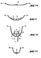
- FIG. 6 shows a urine collector 1 of the first embodiment variant in a worn position in cross section in the area of the urethral outlet 12.
- the small labia 13 are usually within the collector structure 11, whereas the large labia 14 between this and the outside by means of the borders 18, respectively.
- whose lateral areas 18a and 18b are reinforced blank 2.
- the wet zone 22 and the wet zone 23 are clearly separated from one another by the seal achieved in the contact area 20 (FIG. 4).
- the urine emerging from the urethra can freely pass the spacers 25 past the inner wall of the collector structure 11 into the collecting space 19 and from there through the outlet 7 urine, which occurs in the case of unfortunate movements or positions of the woman, or in the case of carelessly applied urine Collector 1 reaches the wet zone 23, can also be passed through the drain holes 24 into the collecting space 19, from where it can flow freely.
- a second embodiment according to FIG. 7 can be used .
- a urine collector 1 for women according to the invention is shown in longitudinal section in FIG. 8.
- the blank 2 has on the inside the collector structure 11, below which the collecting space 19 extends, from which the outlet 7 leads out.
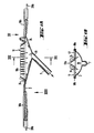
- FIG. 9 shows the urine collector 1 according to FIG. 8 from the direction of arrow IX.
- the blank 2 which is reinforced all around by the borders 18, 18a, 18b.
- the collector structure 11 In the rear, narrower area of the blank 2 is the collector structure 11, consisting of the two side parts 11 a and 11 b; arranged; under which the collecting space 19 with the outlet 7, which is not visible here, is located.
- the two side parts 11 a and 11 b of the collector structure 11 are prevented by the spacers 25 from collapsing.
- the borders 18 and the collector structure 11 run out into the rear bead 17, which closes the urine collector 1 except for the shoulder 27.
- the front bead 15 is oriented from a side border area 18a across the blank 2 with its longitudinally arranged reinforcement band 26 to the other side border area 18b. It forms the front end of the wet zone 23.
- a ring 28a At the two front ends 2a and 2b of the blank 2 there is a ring 28a, respectively. 28b arranged on which the waist belt 3 (Fig. 1) can be hung.
- the collector structure 11 As can be seen particularly well in this figure, there is the collector structure 11, respectively.
- a drain hole 24 is advantageously arranged in the connection 29 in each V formed by the side parts 11 and 11b, in such a way that a free drain of the urine into the collecting space 19 underneath is also ensured here.
- the blank 2 is made of a slightly flexible material, so that the tensile forces exerted on the rings 28a and 28b and the shoulder 27 by the belts 3 and 4 when the urine collector is carried lead to the blank 2 being given a shell-like shape.
- the urine collector according to the invention can also be easily placed over the collector structure 11 sterile gauze can be worn without losing its effectiveness.
- this embodiment variant of the urine collector according to the invention has two rings 28a, 28b both at the front and at the rear, which, as can be seen particularly from FIGS. 16 and 17, are embedded in the blank 2. It is advisable to make the rear rings square and the front rings round, as shown in Fig. 15.
- the collecting space 19 can essentially be formed from a film connected to the blank 2 on the border side regions 18a and 18b and the beads 15 and 17.
- FIGS. 24 to 26 show a fourth embodiment of the urine collector according to the invention, in which the collector structure 11, respectively. whose side parts 11 and 11b are connected to one another at the top in the regions of the inward-facing V's.
- the spacer webs can thus be omitted without risking that the collector structure 11 can be pressed together by external forces.
- This fourth embodiment variant also differs from the other three described above in that the blank 2 has a substantially smaller surface and is very deeply cut at the back.
- the borders 18a and 18b are provided with a sealing lip in their lateral areas 18, which can of course also be provided in the other design variants.
- the drain holes 24 are triangular, so that they adapt to the V-shape of the collector structure 11.
- the urine collector can instead of a waist belt 3 (FIG. 1) also be worn with a type of braces, which has a band between the breasts at the front, which extends over the The shoulders are separated and the back runs twice to be connected to the two rings 28a and 28b.
- the present urine collector according to the invention has very significant advantages over all known devices for the same purpose. It is kept as small as possible and collects the urine that flows out in an uncontrolled manner as close as possible to the point at which it emerges. This practically limits the area of the female abdomen that remains permanently more or less moist to the small labia. This largely prevents the skin from becoming wounded and strained.
- the urine collector described above can be constructed differently in details if this proves to be useful.
- another connection to the belts can be provided.
- the shape of the blank can be chosen differently, which may be due to the anatomical conditions.
- the extension of the collector structure and the size of the cut must of course be adapted to the circumstances, so that a urine collector will look different for a young, slim woman than for an old, diverent woman.
- Women who are wheelchair bound or otherwise have to sit for a long time can advantageously use a horseshoe-shaped pillow that is open at the front and thus facilitates the outflow of urine from the collector.
Landscapes
- Health & Medical Sciences (AREA)
- Epidemiology (AREA)
- Nursing (AREA)
- Orthopedic Medicine & Surgery (AREA)
- Engineering & Computer Science (AREA)
- Biomedical Technology (AREA)
- Heart & Thoracic Surgery (AREA)
- Vascular Medicine (AREA)
- Life Sciences & Earth Sciences (AREA)
- Animal Behavior & Ethology (AREA)
- General Health & Medical Sciences (AREA)
- Public Health (AREA)
- Veterinary Medicine (AREA)
- Orthopedics, Nursing, And Contraception (AREA)
Abstract
Description
Die vorliegende Erfindung betrifft einen Urin- Sammler für inkontinente Frauen gemäss dem Oberbegriff des Patentanspruches 1.The present invention relates to a urine collector for incontinent women according to the preamble of
Bei inkontinenten Frauen stellt sich das Problem des Auffangens und Sammelns des unkontrolliert aus der Harnblase und damit der Harnröhre austretenden Urins aus anatomischen Gründen wesentlich anders und viel komplizierter als beim Mann, wo ein Auffangbeutel über das Glied gestülpt werden kann.In the case of incontinent women, the problem of collecting and collecting the urine that escapes uncontrollably from the urinary bladder and thus the urethra is, for anatomical reasons, much different and much more complicated than in men, where a collecting bag can be put over the limb.
Da bei der Frau die Harnröhre zwischen den inneren oder kleinen Schamlippen endet, wo kein Auffangbeutel oder sonstiger Sammler direkt befestigt werden kann, haben sich Frauen bis anhin meistens mit Windeln oder ähnlichem beholfen, da die bekannten Sammler, z. B. nach der JP-A-1 062 936 oder ähnliche, unpraktisch in der Handhabung und/oder unangenehm im Tragen sowie oft undicht sind. Zudem ist es nicht jedermanns Sache, gemass einem anderen bekannten Vorschlag, einen Analstimulator zu tragen, der unter anderem auch den Blasenschliessmuskel derart stimulieren soll, dass die Inkontinenz überwunden wird.Since the woman's urethra ends between the inner or small labia, where no collection bag or other collector can be attached directly, women have so far mostly used diapers or the like, because the known collectors, e.g. B. according to JP-A-1 062 936 or similar, impractical to use and / or uncomfortable to wear and often leak. In addition, it is not everyone's cup of tea, according to another known proposal, to wear an anal stimulator which, among other things, should also stimulate the bladder sphincter muscle in such a way that incontinence is overcome.
Auch das Urinal für Frauen mit Inkontinenz gemäss der DE-A-1 766 795, bei welchem ein mit einer Schale verbindbarer Urin-Auffangbeutel vorhanden ist, kann nicht befriedigen, da ein in die Harnröhre einzuführender Stift als Verdrehsicherung des Urinals verwendet wird, der sehr störend wirkt. Er ist aber notwendig, um einigermassen sicherzustellen, dass ein rings um den Harnröhrenaustritt herum angeordneter ringförmiger Ansatz, aus dessen Zentrum heraus ein Schlauch abgeht, als Dichtung wirkt.The urinal for women with incontinence according to DE-A-1 766 795, in which there is a urine collection bag that can be connected to a shell, cannot be satisfactory, since a pin that is inserted into the urethra is used to prevent the urinal from rotating, which is very difficult is disturbing. However, it is necessary in order to ensure to some extent that a ring-shaped approach arranged around the urethral outlet, from the center of which a tube emerges, acts as a seal.
Der aus der US-A-3 194 238 bekannte Urinsammler mit zwei elastisch federnd ausgebildeten Dichtungsringen oder -wulsten befriedigt ebenfalls nicht, denn auch bei ihm kann der unkontrolliert aus der Harnröhre austretende Urin, insbesondere wenn er über den inneren Dichtungsring, aus dessen Zentrum heraus der Urin in einen Auffangbeutel abgeführt wird, hinaus gelangt, zu einem Gefühl des Nassseins führen und mangels Abflussmöglichkeit in den Auffangbeutel dem Körper entlang entweichen.The urine collector known from US-A-3 194 238 with two elastically resilient sealing rings or beads is also unsatisfactory, since the urine which emerges from the urethra in an uncontrolled manner, particularly when it passes through the inner sealing ring, can also escape from its center the urine is drained into a collecting bag, gets out, leads to a feeling of being wet and, due to the lack of drainage in the collecting bag, escapes along the body.
Der vorliegenden Erfindung liegt daher die Aufgabe zugrunde, einen Urin-Sammler für inkontinente Frauen vorzuschlagen, der in seiner Handhabung einfach ist, beim andauernden Tragen möglichst wenig stört und in allen Lagen und Situationen ein Maximum an Sicherheit, d. h. Dichtigkeit bietet.The present invention is therefore based on the object of proposing a urine collector for incontinent women which is simple to use, disturbs as little as possible when worn continuously and provides maximum safety in all situations and situations, i. H. Offers tightness.
Erfindungsgemäss wird diese Aufgabe durch einen Urin-Sammler gemäss dem Patentanspruch 1 gelöst.According to the invention, this object is achieved by a urine collector according to
Vorteilhafte Ausführungsvarianten eines erfindungsgemässen Urin-Sammlers werden hiernach an Hand der Zeichnung im Detail beschrieben. Letztere zeigt in
- Fig. 1 einen von einer Frau getragenen erfindungsgemässen Urin-Sammler mit den wesentlichsten Zubehören von vorn, in
- Fig. 2 dasselbe von schräg hinten, in
- Fig. 3 einen Längsschnitt durch einen weiblichen Unterkörper mit getragenem Urin- Sammler, ebenfalls im Längsschnitt, in
- Fig. 4 eine perspektivische Ansicht einer weiblichen Scham mit darauf aufzusetzendem Urin-Sammler, ebenfalls perspektivisch, in
- Fig. 5 einen Urin-Sammler in der Lage wie er sich am Unterleib getragen präsentiert, perspektivisch von hinten, in
- Fig. 6 einen Querschnitt durch eine erste Ausführungsvariante eines erfindungsgemässen Urin-Sammlers, getragen, in
- Fig. 7 einen Querschnitt durch eine zweite Ausführungsvariante eines erfindungsgemässen Urin-Sammlers, getragen, in
- Fig. 8 einen Längsschnitt durch einen Urin- Sammler gemäss der ersten Ausführungsvariante, in
- Fig. 9 die Draufsicht auf den Urin-Sammler nach Fig. 8 in Richtung des Pfeilers IX, in den
- Fig. 10 bis 13 Schnitte durch den Urin-Sammler gemäss Fig. 8 entlang den Linien X-X, resp. XI-XI, resp. XII-XII, resp. XIII-XIII, in
- Fig. 14 eine teilweise geschnittene perspektivische Ansicht einer dritten Variante eines erfindungsgemässen Urin-Sammlers, in
- Fig. 15 eine Draufsicht auf den Urin-Sammler gemäss Fig. 14, in den
- Fig. 16 und 17 Längsschnitte durch Details dieser Variante eines Urin-Sammlers, in
- Fig. 18 einen Längsschnitt durch den Urin- Sammler gemäss Fig. 15 entlang der Linie XVIII - XVIII, in
- Fig. 19 einen Querschnitt durch denselben Urin-Sammler, entlang der Linie XIX - XIX der Fig. 18 und 21, in den
- Fig. 20, 21 und 22 Details der Fig. 15, 18 und 19 in grösserem Masstab, in
- Fig. 23 eine Unteransicht der dritten Ausführungsvariante eines erfindungsgemässen Urin-Sammlers, wobei ein Teil des Auffangraumes teilweise weggebrochen ist, in
- Fig. 24 eine vierte Ausfürungsvariante eines erfindungsgemässen Urin-Sammlers in perspektivischer Sicht, teilweise geschnitten, in
- Fig. 25 eine Draufsicht auf diese vierte Ausführungsvariante und in
- Fig. 26 einen Längsschnitt durch den Urin- Sammler gemäss Fig. 25, entlang der Linie XXVI - XXVI.
- Fig. 1 worn by a woman urine collector according to the invention with the most essential accessories from the front, in
- Fig. 2 the same from obliquely behind, in
- Fig. 3 shows a longitudinal section through a female lower body with a worn urine collector, also in longitudinal section, in
- Fig. 4 is a perspective view of a female pubic with urine collector to be placed thereon, also in perspective, in
- Fig. 5 shows a urine collector in the position as it is worn on the abdomen, in perspective from behind, in
- 6 shows a cross section through a first embodiment variant of a urine collector according to the invention, worn, in
- 7 shows a cross section through a second embodiment variant of a urine collector according to the invention, worn, in
- 8 shows a longitudinal section through a urine collector according to the first embodiment, in
- Fig. 9 is a plan view of the urine collector of FIG. 8 in the direction of the pillar IX, in the
- 10 to 13 sections through the urine collector according to FIG. 8 along the lines XX, respectively. XI-XI, resp. XII-XII, resp. XIII-XIII, in
- 14 is a partially sectioned perspective view of a third variant of a urine collector according to the invention, in
- 15 is a plan view of the urine collector according to FIG. 14, in the
- 16 and 17 longitudinal sections through details of this variant of a urine collector, in
- FIG. 18 shows a longitudinal section through the urine collector according to FIG. 15 along the line XVIII - XVIII, in
- Fig. 19 shows a cross section through the same urine collector, along the line XIX - XIX of Figs. 18 and 21, in the
- 20, 21 and 22 details of FIGS. 15, 18 and 19 on a larger scale, in
- 23 is a bottom view of the third embodiment variant of a urine collector according to the invention, with part of the collecting space partially broken away, in FIG
- 24 shows a fourth embodiment variant of a urine collector according to the invention in a perspective view, partly in section, in FIG
- 25 is a plan view of this fourth embodiment variant and in
- 26 shows a longitudinal section through the urine collector according to FIG. 25, along the line XXVI-XXVI.
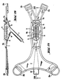
In Fig. 1 ist der erfindungsgemässe Urin- Sammler an einem weiblichen Unterleib getragen in seiner Gebrauchslage dargestellt, wobei Teile davon nur in gestrichelten Linien sichtbar sind, da sie durch den einen Oberschenkel der Frau, resp. deren Unterleib verdeckt sind. Man erkennt in dieser Figur die folgenden allgemeinen Teile des erfindungsgemässen Urin-Sammlers mit den zugehörigen Hilfsmitteln: den generell mit 1 bezeichneten Urin-Sammler und insbesondere dessen Zuschnitt 2, der mit einem Leibgürtel 3 und einem zweiteiligen Hilfsgürtel 4a, 4b in der richtigen Lage zwischen den Oberschenkeln 5a, 5b der den Urin-Sammler tragenden Frau, resp. an deren Scham 6 gehalten wird. Am Zuschnitt 2 erkennt man einen Auslauf 7, der über ein Zwischenstück 8 in einen bekannten AuffangBeutel 9 mit Schenkelriemen 10a und 10b mündet. Eine sich im Zuschnitt 2 befindliche Kollektor-Struktur 11 ist hier lediglich angedeutet. In dieser Figur ersieht man, dass der erfindungsgemässe Urin-Sammler 1, ähnlich wie ein Bikini-Unterteil getragen wird, wobei der korrekte Sitz des Leibgürtels 3 und des Hilfsgürtels 4a, 4b im wesentlichen die richtige Lage des Zuschnittes 2 mit der darin angeordneten Kollektor-Struktur 11 sichert.In Fig. 1, the urine collector according to the invention is shown worn on a female abdomen in its position of use, parts of which are only visible in dashed lines because they are through one thigh of the woman, respectively. whose abdomen is covered. The following general parts of the urine collector according to the invention with the associated aids can be seen in this figure: the urine collector generally designated 1 and in particular its
In Fig. 2 ist der Urin-Sammler 1 mit all den in Fig. 1 bezeichneten Hilfsmitteln von der Rückseite der ihn tragenden Frau gezeigt, im wesentlichen zwangsläufig in gestrichelten Linien.In Fig. 2 the
In Fig. 3 ist im Längsschnitt dargestellt, wie der erfindungsgemässe Urin-Sammler 1 im Schitt der Frau liegt, wobei die Lage der Kollektor-Struktur 11 bezüglich des Harnröhrenaustritts 12 und der kleinen und der grossen Schamlippen 13 resp. 14 hier nicht klar ersichtlich ist. Man erkennt hier aber deutlich, wie eine vordere Wulst 15 gegen das Schambein 16 hin den Urin-Sammler 1 gegen vorne abdichtet, wogegen eine hintere Wulst 17 die Abdichtung gegen hinten sicherstellt. Dies, zusätzlich zu der durch die Kollektor-Struktur 11 in Zusammenwirkung mit den Schamlippen 13,14 erzielten Dichtung. Zudem dient die rund um den Zuschnitt 2 herum laufende Bordure 18 als weitere Dichtung.In Fig. 3 it is shown in longitudinal section how the
Es ist empfehlenswert, nicht nur einen, wie hier dargestellt, einfachen Beutel 9 zu verwenden, sondern einen mit Rückschlagventil, und Auslaufstutzen, um zu verhindern, dass je nach Stellung, die die Frau einnimmt, sich bereits im Beutel 9 befindlicher Urin zurück in den Urin- Sammler 1 fliessen kann und das Entleeren des Beweis 9, ohne ihn abnehmen zu müssen, zu ermöglichen.It is advisable to use not only a
Man erkennt in dieser Figur, dass der erfindungsgemässe Urin-Sammler 1 kleinstmöglich gehalten ist und nur den absolut notwendigen Schambereich 6 abdeckt.It can be seen in this figure that the
In Fig. 4 ist in einer perspektivischen Explosionszeichnung dargestellt, wohin die einzelnen Teile des erfindungsgemässen Urin-Sammlers 1 am Unterleib der Frau, resp. deren Scham 6 zu liegen kommen. Man erkennt, schematisch dargestellt, die Anordnung der kleinen Schamlippen 13, zwischen welchen die Harnröhre bei 12 austritt, und ausserhalb von welchen sich die grossen Schamlippen 14 befinden, die im Normalfall, nicht wie hier dargestellt, geöffnet sind, sondern über den kleinen Schamlippen 13 liegen.In Fig. 4 is shown in a perspective exploded view where the individual parts of the
In der Regel wird eine Frau, die nicht übergrosse kleine Schamlippen 13 hat, die hier gezeigte erste Ausführungsvariante des Urin-Sammlers 1 so tragen, dass die Kollektor- Struktur 11, auf deren genaue Ausgestaltung später eingegangen wird, zwischen kleine und grosse Schamlippen 13, resp. 14 in den mit 20 bezeichneten Auflagebereich zu liegen kommt, wie dies auch aus Fig. 6 ersichtlich ist. Derart wird eine innere Zone begrenzt, über die hinaus sich aus dem Harnröhrenaustritt 12 heraus tretender Urin im Normalfall nicht ausbreiten kann, da die Kollektor-Struktur 11 den den inneren Schamlippen 13 entlang fliessenden Urin in den unterhalb der Kollektor-Struktur 11 angeordneten Auffangraum 10 (Fig. 3) ableitet und die Schamlippen 13 und 14 sich eng an die Kollektor-Struktur 11 anlegen. Diese Nasszone 22 (Fig. 5) ist bei allen üblicherweise eingenommenen Stellungen der Frau, sowie bei nicht übertriebenen Bewegungen, soweit dicht, dass Urin nicht aus ihr ausläuft. Sollte dies unerwarteterweise dennoch einmal vorkommen, so sorgen die seitlichen Bereiche 18a und 18b der Bordure, die vorne in die vordere Wulst 17 übergehen, ausserhalb der grossen Schamlippen 14 in dem mit 21 bezeichneten Auflagebereich für eine nochmalige Abdichtung der Schamgegend nach aussen hin. Eventuell in diese äussere Zone, die Feuchtzone 23 (Fig. 5) vordringender Urin wird ebenfalls entlang der Kollektor-Struktur 11 und durch Ablusslöcher 24 (Fig. 5) hindurch in den Auffangraum 19 (Fig. 3) abgeleitet. Aus diesem fliesst der Urin durch den Auslauf 7 aus dem Urin-Sammler 1 heraus, vorteilhafterweise über ein Zwischenstück 8 in einen Beutel 9 (Fig. 3).As a rule, a woman who does not have oversized
In Fig. 5 ist der erfindungsgemässe Urin- Sammler 1 in der getragenen Stellung von hinten gezeigt, wobei der Unterleib der Frau nur angedeutet und die Details der durch den Urin- Sammler 1 abgedeckten und mit ihm Zusammenwirkenden Schamgegend weggelassen sind. Man erkennt in dieser Figur gut die schalenförmige Gestalt, die der Urin- Sammler 1 am Unterleib einnimmt. Gut sichtbar sind auch die Nasszone 22 innerhalb der Kollektor-Struktur 11 und die Feuchtzone 23, die durch die seitlichen Bereiche 18a und 18b der Bordure 18 sowie der vorderen Wulst 15 und der hinteren Wulst 17 begrenzt wird. Gut sichtbar sind in dieser Figur auch Distanzstege 25 zwischen den beiden Seitenteilen 11 a und 11 b der Kollektor-Struktur 11, deren Aufgabe es ist, zu verhindern, dass die beiden Seitenteile 11a a und 11b durch äussere Kräfte, der grossen Schamlippen 14 und/oder der Schenkel 5a, 5b, zusammengedrückt werden, derart, dass der aus der Harnröhre austretende Urin nicht mehr zwischen ihnen abgeleitet werden kann.5 shows the
In Fig. 6 ist ein Urin-Sammler 1 der ersten Ausführungsvariante in getragener Stellung im Querschnitt im Bereich des Harnröhrenaustrittes 12 dargestellt. Man erkennt dabei den Zuschnitt 2 mit der darin angeordneten Kollektor-Struktur 11, deren beide Seitenteile 11 und 11b mittels der Distanzstege 25 auseinanderge halten werden. Die kleinen Schamlippen 13 liegen hier üblicherweise innerhalb der Kollektor-Struktur 11, wogegen die grossen Schamlippen 14 zwischen dieser und dem aussen mittels der Bordure 18, resp. deren seitlichen Bereichen 18a und 18b verstärkten Zuschnitt 2 liegen. Die Nasszone 22 sowie die Feuchtzone 23 sind durch die im Auflagebereich 20 (Fig. 4) erzielte Dichtung klar voneinander getrennt. Der aus der Harnröhre aus tretende Urin kann ungehindert an den Distanzstegen 25 vorbei entlang der Innenwand der Kollektor-Struktur 11 in den Auffangraum 19 und von da durch den Auslauf 7 abfliessen Urin, der bei unglücklichen Bewegungen oder Stellungen der Frau, oder bei unsorgfältig appliziertem Urin-Sammler 1 in die Feuchtzone 23 gelangt, kann durch die Abflusslöcher 24 ebenfalls in den Auffangraum 19 geleitet werden, von wo er ungehindert abfliessen kann.6 shows a
In Fällen, wo durch anatomische Besonderheiten oder erhöhte Bewegungsintensität oder die häufige und langdauernde Einnahme einer liegenden Stellung mittels der hiervor beschriebenen ersten Ausführungsvariante des erfindungsgemässen Urin-Sammlers 1 die Dichtigkeit desselben in Frage gestellt scheint, kann eine zweite Ausführungsvariante gemäss Fig. 7 zur Anwendung gelangen. Diese unterscheidet sich von ersterer nur dadurch, dass sie eine doppelte Kollektor-Struktur 11 aufweist, bei der innerhalb deren Teile 11a und 11b zwei im wesentlichen parallel dazu verlaufende Teile 11c und 11d angeordnet sind. Diese werden zwischen den Kleinen Schamlippen 13 getragen, derart, dass der aus der Harnröhre 12 austetende Urin von ihnen direkt aufgefangen wird.In cases where anatomical peculiarities or increased movement intensity or the frequent and long-term use of a lying position by means of the above-described first embodiment of the
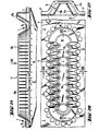
In Fig. 8 ist ein erfindungsgemässer Urin- Sammler 1 für Frauen im Längsschnitt dargestellt. Man erkennt den Zuschnitt 2 mit seiner aussenherum laufenden Bordure 18 als Dichtung und Verstärkung und einem im vorderen Bereich zentral und längs angeordneten Verstärkungsband 26 (Fig. 9). Der Zuschnitt 2 weist innen die Kollektor-Struktur 11 auf, unterhalb von welcher sich der Auffangraum 19 erstreckt, aus welchem der Auslauf 7 herausführt. Die vorne quer durch den Zuschnitt 2 hindurchlaufende vordere Wulst 15, die zusammen mit den seitlichen Bereichen 18a und 18b der Bordure 18 sowie der hinteren Wulst 17 die Feuchtzone 23 begrenzt, ist ebenfalls gut zu erkennen. An letztere anschliessend erkennt man einen Ansatz 27, der der Befestigung resp. dem Durchziehen der hier nicht dargestellten Hilfsgürtel 4a/4b dient.A
In Fig. 9 ist der Urin-Sammler 1 nach Fig. 8 aus der Richtung des Pfeiles IX dargestellt. Man erkennt wiederum den Zuschnitt 2, der durch die Bordure 18, 18a, 18b rundum verstärkt ist. Im hinteren, schmaleren Bereich des Zuschnittes 2 ist die Kollektor-Struktur 11, bestehend aus den zwei Seitenteilen 11 a und 11 b; angeordnet; unter welcher sich der Auffangraum 19 mit dem hier nicht sichtbaren Auslauf 7 befindet. Die beiden Seitenteile 11 a und 11 b der Kollektor-Struktur 11 sind durch die Distanzstege 25 daran gehindert, zu kollabieren. Hinten laufen die Bordure 18 und die Kollektor-Struktur 11 in die hintere Wulst 17 aus, die den Urinsammler 1 bis auf den Ansatz 27 nach hinten ab schliesst. Im vorderen breiteren Bereich zient sich die vordere Wulst 15 von einem seitlichen Bordurenbereich 18a quer über den Zuschnitt 2 mit seinem längs angeordneten Verstärkungsband 26 bis zum anderen seitlichen Bordurenbereich 18b. Sie bildet den vorderen Abschluss der Feuchtzone 23. An den beiden vorderen Enden 2a und 2b des Zuschnittes 2 ist je ein Ring 28a, resp. 28b angeordnet, an welchen der Leibgürtel 3 (Fig. 1) eingehängt werden kann.9 shows the
Wie in dieser Figur speziell gut erkennbar ist, besteht die Kollektor-Struktur 11, resp. deren Seitenteile 11 und 11 b aus zick-zack-förmigen, vorteilhafterweise nach innen geneigten Erhebungen. Diese Formgebung erinnert an die Oberfläche eines Kaktus und dient wie bei diesem dazu, jede auf sie treffende Feuchtigkeit in die Spitzen der V's zu ziehen, wo sie nach unten abfliessen kann. Dies geschieht bei der Kollektor-Struktur 11 sowohl innen, wo der Urin vom unteren Rand ungehindert in den Auffangraum 19 ablaufen kann, wie aussen, wo gegebenenfalls da auftretender Urin ebenfalls in die Spitzen der V's gezogen und dort nach unten geleitet und damit er sich nicht in der Feuchtzone 23 sammelt, ist vorteilhafterweise in jedem durch die Seitenteile 11 und 11b geformten V ein Abflussloch 24 in der Verbindung 29 angeordnet, derart, dass auch hier ein freier Abfluss des Urins in den darunter liegenden Auffangraum 19 gewährleistet ist.As can be seen particularly well in this figure, there is the
Vorteilhafterweise wird der Zuschnitt 2 aus leicht flexiblem Material hergestellt, so dass die beim Tragen des Urin-Sammlers auf die Ringe 28a und 28b sowie den Ansatz 27 durch die Gürtel 3 und 4 ausgeübten Zugkräfte dazu führen, dem Zuschnitt 2 eine schalenförmige Gestalt zu geben. Dies führt zu einem besseren Passitz des Urin-Sammlers und damit zu einer besseren Abdichtung desselben, insbesondere in den Auflagebereichen 20 und 21. Aus Komfort- und Hygiene gründen kann der erfindungsgemässe Urin-Sammler ohne weiteres auch mit einer über die Kollektor-Struktur 11 gelegten sterilen Gaze getragen werden, ohne von seiner Wirksamkeit zu verlieren.Advantageously, the blank 2 is made of a slightly flexible material, so that the tensile forces exerted on the
In den Fig. 10 bis 13 sind Querschnitte durch den Urin-Sammler gemäss der Fig. 8 und 9 dargestellt. Diese Figuren bedürfen keiner speziellen Erläuterung.10 to 13 show cross sections through the urine collector according to FIGS. 8 and 9. These figures do not require any special explanation.
In den Fig. 14 bis 23 ist eine dritte Ausführungsvariante des erfindungsgemässen Urin-Sammlers dargestellt, bei der der Zuschnitt 2 eine leicht andere Form aufweist als in den zwei vorerwähnten Ausführungsvarianten. Zudem ist die hintere Wulst 17 mit einer markanten Erhöhung 17a versehen, um gegen den Gesäss-Spalt hin eine verbesserte Dichtung zu erziehlen. Ferner weist dieser Urin-Sammler zwischen den Seitenteilen 11 und 11b der Kollektorstruktur 11 keine Distanzstege auf. Die Kollektorstruktur 11 steht frei über dem Auffangraum 19, aus dem der Auslauf 7 herausführt. Zwecks Erhöhung des Tragkomfortes weist diese Ausführungsvariante des erfindungsgemässen Urin-Sammlers sowohl vorne als auch hinten je zwei Ringe 28a, 28b auf, die, wie sich speziell aus den Fig. 16 und 17 ergibt, in den Zuschnitt 2 eingelassen sind. Es ist empfehlenswert, die hinteren Ringe eckig und die vorderen rund auszugestalten, wie dies in Fig. 15 dargestellt ist.14 to 23 show a third embodiment variant of the urine collector according to the invention, in which the blank 2 has a slightly different shape than in the two aforementioned embodiment variants. In addition, the
Die Längs- und Querschnitte dieser dritten Ausführungsvariante in den Fig. 18 und 19 bedürfen keiner speziellen Erklärungen. Die Fig. 20, 21 und 22, die den in Fig. 15 innerhalb des strichpunktierten Rechtecks XX liegenden Bereich des erfindungsgemässen Urin-Sammlers in grösserem Maßstab zeigen, veranschaulicht gut, wie die Kollektor-Struktur 11 und die hintere Wulst 17 mit ihrer Erhöhung 17a zusammenwirken. In Fig. 20 ist auch gut ersichtlich, dass bei dieser Ausführungsvariante die Ausflusslöcher 24 Vorteilhafterweise rund um die Kollektor-Struktur 11 herum angeordnet sind.The longitudinal and cross sections of this third embodiment variant in FIGS. 18 and 19 do not require any special explanations. 20, 21 and 22, which show the area of the urine collector according to the invention lying within the dash-dotted rectangle XX on a larger scale, illustrates well how the
Aus Fig. 23 erkennt man, dass der Auffangraum 19 im wesentlichen aus einer mit dem Zuschnitt 2 an den Bordurenseitenbereichen 18a und 18b sowie den Wulsten 15 und 17 verbundenen Folie gebildet sein kann.From FIG. 23 it can be seen that the collecting
Die Fig. 24 bis 26 zeigen eine vierte Ausführungsvariante des erfindungsgemässen Urin-Sammlers, bei der die Kollektor-Struktur 11, resp. deren Seitenteile 11 und 11b oben, in den Bereichen der nach innen weisenden V's miteinander verbunden sind. Damit können die Distanzstege weggelassen werden, ohne zu riskieren, dass die Kollektor-Struktur 11 durch äussere Kräfte zusammengedrückt werden kann. Diese vierte Ausführungsvariante unterscheidet sich von den drei anderen hiervor beschriebenen ferner noch dadurch, dass der Zuschnitt 2 eine wesentlich kleinere Oberfläche aufweist und hinten sehr weit eingeschnitten ist. Zudem ist die Bordure 18 in ihren seitlichen Bereichen 18a und 18b mit einer Dichtungslippe versehen, was selbstverständlich auch bei den anderen Ausführungsvarianten vorgesehen werden kann. Im Gegensatz zu diesen ist hier ferner vorgesehen, die Abflusslöcher 24 dreieckig zu gestalten, so dass sie sich der V-Form der Kollektorstruktur 11 anpassen. Sofern der Zuschnitt 2 vorne in der Mitte eine Lasche 30 aufweist, kann der Urin-Sammler an Stelle eines Leibgürtels 3 (Fig. 1) auch mit einer Art Hosenträger getragen werden, der vorne ein zwischen den Brüsten liegendes Band aufweist, das sich über die Schultern auftrennt und hinten 2-fach verläuft, um mit den beiden Ringen 28a und 28b verbunden zu werden.24 to 26 show a fourth embodiment of the urine collector according to the invention, in which the
Der Fachmann erkennt leicht, dass der vorliegende erfindungsgemässe Urin-Sammler gegenüber allen bekannten Vorrichtungen für denselben Zweck ganz wesentliche Vorteile aufweist. Er ist möglich klein gehalten und sammelt den unkontrolliert ausfliessenden Harn möglichst nahe an dessen Austrittsstelle. Damit wird derjenige Bereich des weiblichen Unterleibes, der dauernd mehr oder weniger feucht bleibt, praktisch auf die kleinen Schamlippen beschränkt. Dies verhindert weitgehend ein Wundwerden und übermässiges Strapazieren der Haut.The person skilled in the art can easily see that the present urine collector according to the invention has very significant advantages over all known devices for the same purpose. It is kept as small as possible and collects the urine that flows out in an uncontrolled manner as close as possible to the point at which it emerges. This practically limits the area of the female abdomen that remains permanently more or less moist to the small labia. This largely prevents the skin from becoming wounded and strained.
Selbstverständlich kann der hiervor beschriebene Urin-Sammler in Details anders aufgebaut werden, wenn sich dies als sinnvoll erweist. Insbesondere kann eine andere Verbindung mit den Gürteln vorgesehen werden. Ferner kann die Form des Zuschnittes anders gewählt werden, was gegebenenfalls durch die anatomischen Verhältnisse bedingt werden kann. Die Ausdehnung der Kollektor-Struktur und die Grösse des Zuschnittes sind natürlich den Gegebenheiten anzupassen, so dass ein Urin- Sammler für eine junge, schlanke Frau anders aussehen wird als für eine alte, korpulente Frau.Of course, the urine collector described above can be constructed differently in details if this proves to be useful. In particular, another connection to the belts can be provided. Furthermore, the shape of the blank can be chosen differently, which may be due to the anatomical conditions. The extension of the collector structure and the size of the cut must of course be adapted to the circumstances, so that a urine collector will look different for a young, slim woman than for an old, corpulent woman.
Frauen, die an den Rollstuhl gebunden sind, oder sonst lange sitzen müssen, können vorteilhafterweise ein hufeisenförmiges Kissen verwenden, das vorne offen ist und damit den Ausfluss des Urins aus dem Sammler erleichtert.Women who are wheelchair bound or otherwise have to sit for a long time can advantageously use a horseshoe-shaped pillow that is open at the front and thus facilitates the outflow of urine from the collector.
Selbstverständlich sind die unterschiedlichen hiervor beschriebenen Ausführungsvarianten des erfindungsgemässen Urin-Sammlers miteinander verbindbar, sodass sich andere, hier nicht erwähnte Kombinationen von DetailKonstruktionen ergeben können.Of course, the different design variants of the urine collector according to the invention described above can be connected to one another, so that other combinations of detail constructions, not mentioned here, can result.
Claims (4)
Applications Claiming Priority (2)
| Application Number | Priority Date | Filing Date | Title |
|---|---|---|---|
| CH2375/84A CH665556A5 (en) | 1984-05-15 | 1984-05-15 | URINE COLLECTOR FOR INCONTINENT WOMEN. |
| CH2375/84 | 1984-05-15 |
Publications (2)
| Publication Number | Publication Date |
|---|---|
| EP0181354A1 EP0181354A1 (en) | 1986-05-21 |
| EP0181354B1 true EP0181354B1 (en) | 1988-09-21 |
Family
ID=4232302
Family Applications (1)
| Application Number | Title | Priority Date | Filing Date |
|---|---|---|---|
| EP85901963A Expired EP0181354B1 (en) | 1984-05-15 | 1985-05-14 | Urine collector for incontinent women |
Country Status (5)
| Country | Link |
|---|---|
| US (1) | US4692160A (en) |
| EP (1) | EP0181354B1 (en) |
| JP (1) | JPS61502100A (en) |
| CH (1) | CH665556A5 (en) |
| DE (1) | DE3565047D1 (en) |
Cited By (1)
| Publication number | Priority date | Publication date | Assignee | Title |
|---|---|---|---|---|
| DE102005037762B3 (en) * | 2005-08-10 | 2006-09-21 | Ulbrich, Ursula | Urine receptor for use by women comprises a tube having a closed end and an open end separably sealed to a waste receptacle to take the urine |
Families Citing this family (45)
| Publication number | Priority date | Publication date | Assignee | Title |
|---|---|---|---|---|
| US4840624A (en) * | 1982-09-24 | 1989-06-20 | Lee Henry J | Female condom device |
| US5267988A (en) * | 1992-11-25 | 1993-12-07 | Farkas Barry L | Non-invasive female urine collection device |
| US5411495A (en) * | 1993-12-20 | 1995-05-02 | Willingham; Clara J. | Systems for receiving and storing urine from a female patient |
| US5586978A (en) * | 1994-11-07 | 1996-12-24 | Bayne; Donald E. | Incontinence device |
| US5624423A (en) * | 1994-11-30 | 1997-04-29 | Kimberly-Clark Corporation | Absorbent article having barrier means and medial bulge |
| US5545156A (en) * | 1994-12-22 | 1996-08-13 | Kimberly-Clark Corporation | Absorbent article having a preformed member |
| US5613961A (en) * | 1994-12-30 | 1997-03-25 | Kimberly-Clark Corporation | Thin, curved absorbent article having elasticized edges |
| US5984910A (en) * | 1997-11-25 | 1999-11-16 | Berke; Joseph J. | Urinary incontinence device and method |
| US7018366B2 (en) * | 2003-01-17 | 2006-03-28 | William Craig Easter | Vacuum assisted relief system (VARS) |
| US7931634B2 (en) | 2003-12-18 | 2011-04-26 | Kimberly-Clark Worldwide, Inc. | Bodily exudate capturing article |
| GB2412587A (en) * | 2004-03-31 | 2005-10-05 | Oumeima Ben Youssef | Urinary incontinence device |
| GB0410142D0 (en) * | 2004-05-07 | 2004-06-09 | Cunningham Robert W | Urine collection device |
| US20110028944A1 (en) * | 2007-11-21 | 2011-02-03 | Chiu Chin Hung | Female urination pants |
| US20090131916A1 (en) * | 2007-11-21 | 2009-05-21 | Chin-Hung Chiu | Urination pants |
| KR100934254B1 (en) * | 2007-12-28 | 2009-12-30 | 윤권영 | Urine Disposal Device for Women with Disabilities |
| ITFR20090023A1 (en) * | 2009-10-26 | 2010-01-25 | Mario Gino Di | MODEL OF DOUBLE HINGES WITH DEVICE FOR URINE COLLECTION TO WEAR DURING TRAVEL OR LONG CELEBRATIONS, FROM INCONTINENT SUBJECTS |
| GB2491381B (en) * | 2011-06-01 | 2013-05-29 | Ravishankar Anantharamu | A device to collect amniotic fluid,detect and absorb excessive amniotic fluid discharge in pregnant woman |
| US20130237964A1 (en) * | 2012-03-07 | 2013-09-12 | John Kicos | Non-invasive urine directional device, urine collection system, and kit |
| US11806266B2 (en) | 2014-03-19 | 2023-11-07 | Purewick Corporation | Apparatus and methods for receiving discharged urine |
| US10952889B2 (en) | 2016-06-02 | 2021-03-23 | Purewick Corporation | Using wicking material to collect liquid for transport |
| US11090183B2 (en) | 2014-11-25 | 2021-08-17 | Purewick Corporation | Container for collecting liquid for transport |
| US11376152B2 (en) | 2014-03-19 | 2022-07-05 | Purewick Corporation | Apparatus and methods for receiving discharged urine |
| US10226376B2 (en) | 2014-03-19 | 2019-03-12 | Purewick Corporation | Apparatus and methods for receiving discharged urine |
| USD928946S1 (en) | 2016-06-02 | 2021-08-24 | Purewick Corporation | Urine receiving apparatus |
| US10376406B2 (en) | 2016-07-27 | 2019-08-13 | Purewick Corporation | Male urine collection device using wicking material |
| US10973678B2 (en) | 2016-07-27 | 2021-04-13 | Purewick Corporation | Apparatus and methods for receiving discharged urine |
| AU2018221471B2 (en) | 2017-02-14 | 2021-01-21 | Sage Products, Llc | Devices and methods for urine collection |
| US11944740B2 (en) | 2018-05-01 | 2024-04-02 | Purewick Corporation | Fluid collection devices, related systems, and related methods |
| BR112020022196A2 (en) | 2018-05-01 | 2021-02-02 | Purewick Corporation | fluid collection garments |
| JP7114740B2 (en) | 2018-05-01 | 2022-08-08 | ピュアウィック コーポレイション | Fluid collection device and system |
| USD929578S1 (en) | 2019-06-06 | 2021-08-31 | Purewick Corporation | Urine collection assembly |
| USD954393S1 (en) * | 2019-12-16 | 2022-06-14 | Wolfram Kurzweil | Underwear |
| US11207206B2 (en) * | 2020-05-14 | 2021-12-28 | Cm Technologies, Inc. | Fluid removal device |
| US12048643B2 (en) | 2020-05-27 | 2024-07-30 | Purewick Corporation | Fluid collection assemblies including at least one inflation device and methods and systems of using the same |
| USD967409S1 (en) | 2020-07-15 | 2022-10-18 | Purewick Corporation | Urine collection apparatus cover |
| EP4192543A1 (en) | 2020-08-04 | 2023-06-14 | CM Technologies, Inc. | Fecal management systems and methods |
| US11801186B2 (en) | 2020-09-10 | 2023-10-31 | Purewick Corporation | Urine storage container handle and lid accessories |
| US12042423B2 (en) | 2020-10-07 | 2024-07-23 | Purewick Corporation | Fluid collection systems including at least one tensioning element |
| US12048644B2 (en) | 2020-11-03 | 2024-07-30 | Purewick Corporation | Apparatus for receiving discharged urine |
| US12070432B2 (en) | 2020-11-11 | 2024-08-27 | Purewick Corporation | Urine collection system including a flow meter and related methods |
| AU2022211357B2 (en) | 2021-01-19 | 2024-08-01 | Purewick Corporation | Variable fit fluid collection devices, systems, and methods |
| CA3195841A1 (en) | 2021-02-26 | 2022-09-01 | Camille Rose Newton | Fluid collection devices having a sump between a tube opening and a barrier, and related systems and methods |
| US11938054B2 (en) | 2021-03-10 | 2024-03-26 | Purewick Corporation | Bodily waste and fluid collection with sacral pad |
| US12029677B2 (en) * | 2021-04-06 | 2024-07-09 | Purewick Corporation | Fluid collection devices having a collection bag, and related systems and methods |
| US11583434B1 (en) | 2022-05-27 | 2023-02-21 | Carolyn Cimino | Externally wearable female urinary collection and drainage device and related components, systems, kits and methods |
Family Cites Families (8)
| Publication number | Priority date | Publication date | Assignee | Title |
|---|---|---|---|---|
| FR1236346A (en) * | 1958-09-25 | 1960-07-15 | Urinal for women | |
| US3194238A (en) * | 1963-03-01 | 1965-07-13 | Resiflex Lab | Urinary device |
| GB1059680A (en) * | 1965-02-16 | 1967-02-22 | Francis Xavier Keane | Personal wear apparatus for use in incontinent and voluntary micturition |
| DE1766795A1 (en) * | 1968-07-19 | 1971-09-02 | Fromms Blausiegel Gummiwarenfa | Urinal for women with incontinence |
| JPS5250480A (en) * | 1975-10-20 | 1977-04-22 | Tokico Ltd | Emergency reactive actuator |
| JPS535832U (en) * | 1976-07-02 | 1978-01-19 | ||
| SU610523A1 (en) * | 1977-01-03 | 1978-06-15 | Предприятие П/Я А-3469 | Urinal |
| IE54485B1 (en) * | 1982-09-13 | 1989-10-25 | Hollister Inc | Female urinary incontinence device |
-
1984
- 1984-05-15 CH CH2375/84A patent/CH665556A5/en not_active IP Right Cessation
-
1985
- 1985-05-14 EP EP85901963A patent/EP0181354B1/en not_active Expired
- 1985-05-14 JP JP60502070A patent/JPS61502100A/en active Granted
- 1985-05-14 DE DE8585901963T patent/DE3565047D1/en not_active Expired
- 1985-05-14 US US06/818,805 patent/US4692160A/en not_active Expired - Lifetime
Cited By (1)
| Publication number | Priority date | Publication date | Assignee | Title |
|---|---|---|---|---|
| DE102005037762B3 (en) * | 2005-08-10 | 2006-09-21 | Ulbrich, Ursula | Urine receptor for use by women comprises a tube having a closed end and an open end separably sealed to a waste receptacle to take the urine |
Also Published As
| Publication number | Publication date |
|---|---|
| EP0181354A1 (en) | 1986-05-21 |
| WO1985005264A1 (en) | 1985-12-05 |
| CH665556A5 (en) | 1988-05-31 |
| JPH0552219B2 (en) | 1993-08-04 |
| JPS61502100A (en) | 1986-09-25 |
| US4692160A (en) | 1987-09-08 |
| DE3565047D1 (en) | 1988-10-27 |
Similar Documents
| Publication | Publication Date | Title |
|---|---|---|
| EP0181354B1 (en) | Urine collector for incontinent women | |
| DE69310849T2 (en) | Curved hygiene template with plates for attaching to clothing | |
| EP0346477B1 (en) | Disposable diaper | |
| DE69835847T2 (en) | The disposable panty | |
| DE60122807T2 (en) | Hygienic pants | |
| DE69929294T2 (en) | sanitary napkin | |
| DE60028326T2 (en) | Absorbent disposable article | |
| DE69310312T2 (en) | Curved hygiene template with plates for attaching to clothing | |
| DE2933853A1 (en) | PANTIES FOR MALE PEOPLE WITH A BAG TO RECEIVE A BODY FLUID ABSORBING INSOLE | |
| DE68919339T2 (en) | Underpants. | |
| DE69426964T2 (en) | Disposable suction pads | |
| DE60027759T2 (en) | ABSORBENT ARTICLE | |
| DE60033890T2 (en) | Disposable garment | |
| EP0460467A1 (en) | Pants-type disposable clothing | |
| DE212011100007U1 (en) | Portable disposable article | |
| DE602004008508T2 (en) | SUPPORT GARMENT | |
| DE69724474T2 (en) | CLOTHING FOR USE WITH AN ABSORBENT ARTICLE | |
| EP1105079B1 (en) | Hygienic pad for men | |
| DE10144255C1 (en) | Continence underpants, for men and women, has an absorbent insert at the crotch as part of an absorbent strip, sewn to the waist band at the front and rear | |
| EP3793495B1 (en) | Incontinence article in the form of briefs | |
| DE2208810A1 (en) | DEVICE FOR USE IN THE EVENT OF URINE INCONTINENCE | |
| EP4454625A2 (en) | Disposable incontinence article in the form of briefs | |
| DE1766795A1 (en) | Urinal for women with incontinence | |
| EP3742913B1 (en) | Underpants | |
| EP3600195A1 (en) | Underpants |
Legal Events
| Date | Code | Title | Description |
|---|---|---|---|
| PUAI | Public reference made under article 153(3) epc to a published international application that has entered the european phase |
Free format text: ORIGINAL CODE: 0009012 |
|
| 17P | Request for examination filed |
Effective date: 19860122 |
|
| AK | Designated contracting states |
Kind code of ref document: A1 Designated state(s): CH DE FR GB LI SE |
|
| 17Q | First examination report despatched |
Effective date: 19870327 |
|
| GRAA | (expected) grant |
Free format text: ORIGINAL CODE: 0009210 |
|
| AK | Designated contracting states |
Kind code of ref document: B1 Designated state(s): CH DE FR GB LI SE |
|
| PG25 | Lapsed in a contracting state [announced via postgrant information from national office to epo] |
Ref country code: SE Effective date: 19880921 |
|
| REF | Corresponds to: |
Ref document number: 3565047 Country of ref document: DE Date of ref document: 19881027 |
|
| ET | Fr: translation filed | ||
| GBT | Gb: translation of ep patent filed (gb section 77(6)(a)/1977) | ||
| PG25 | Lapsed in a contracting state [announced via postgrant information from national office to epo] |
Ref country code: GB Effective date: 19890514 |
|
| PLBE | No opposition filed within time limit |
Free format text: ORIGINAL CODE: 0009261 |
|
| STAA | Information on the status of an ep patent application or granted ep patent |
Free format text: STATUS: NO OPPOSITION FILED WITHIN TIME LIMIT |
|
| 26N | No opposition filed | ||
| GBPC | Gb: european patent ceased through non-payment of renewal fee | ||
| PGFP | Annual fee paid to national office [announced via postgrant information from national office to epo] |
Ref country code: DE Payment date: 19940531 Year of fee payment: 10 |
|
| PGFP | Annual fee paid to national office [announced via postgrant information from national office to epo] |
Ref country code: FR Payment date: 19940630 Year of fee payment: 10 |
|
| PGFP | Annual fee paid to national office [announced via postgrant information from national office to epo] |
Ref country code: CH Payment date: 19940826 Year of fee payment: 10 |
|
| PG25 | Lapsed in a contracting state [announced via postgrant information from national office to epo] |
Ref country code: LI Effective date: 19950531 Ref country code: CH Effective date: 19950531 |
|
| REG | Reference to a national code |
Ref country code: CH Ref legal event code: PL |
|
| PG25 | Lapsed in a contracting state [announced via postgrant information from national office to epo] |
Ref country code: DE Effective date: 19960201 |
|
| PG25 | Lapsed in a contracting state [announced via postgrant information from national office to epo] |
Ref country code: FR Effective date: 19960229 |
|
| REG | Reference to a national code |
Ref country code: FR Ref legal event code: ST |
|
| REG | Reference to a national code |
Ref country code: FR Ref legal event code: ST |