EP0180955B1 - Digital distance relay - Google Patents
Digital distance relay Download PDFInfo
- Publication number
- EP0180955B1 EP0180955B1 EP85114029A EP85114029A EP0180955B1 EP 0180955 B1 EP0180955 B1 EP 0180955B1 EP 85114029 A EP85114029 A EP 85114029A EP 85114029 A EP85114029 A EP 85114029A EP 0180955 B1 EP0180955 B1 EP 0180955B1
- Authority
- EP
- European Patent Office
- Prior art keywords
- distance measuring
- relay
- distance
- digital
- measuring operation
- Prior art date
- Legal status (The legal status is an assumption and is not a legal conclusion. Google has not performed a legal analysis and makes no representation as to the accuracy of the status listed.)
- Expired - Lifetime
Links
Images


Classifications
-
- H—ELECTRICITY
- H02—GENERATION; CONVERSION OR DISTRIBUTION OF ELECTRIC POWER
- H02H—EMERGENCY PROTECTIVE CIRCUIT ARRANGEMENTS
- H02H7/00—Emergency protective circuit arrangements specially adapted for specific types of electric machines or apparatus or for sectionalised protection of cable or line systems, and effecting automatic switching in the event of an undesired change from normal working conditions
- H02H7/26—Sectionalised protection of cable or line systems, e.g. for disconnecting a section on which a short-circuit, earth fault, or arc discharge has occured
-
- H—ELECTRICITY
- H02—GENERATION; CONVERSION OR DISTRIBUTION OF ELECTRIC POWER
- H02H—EMERGENCY PROTECTIVE CIRCUIT ARRANGEMENTS
- H02H3/00—Emergency protective circuit arrangements for automatic disconnection directly responsive to an undesired change from normal electric working condition with or without subsequent reconnection ; integrated protection
- H02H3/40—Emergency protective circuit arrangements for automatic disconnection directly responsive to an undesired change from normal electric working condition with or without subsequent reconnection ; integrated protection responsive to ratio of voltage and current
Definitions
- the present invention relates to digital distance relays with three steps distance protection, and more specifically to a digital distance relay wherein each of N phases on duty among six phases has distance measuring elements in step 1-3, (see for example, Protective Relaying - N. Chernobrovov - MIR publishers - Moscow - chapter XI).
- the computer member 11 comprises a central processing unit 12 (hereinafter referred to as "CPU"), a setting circuit 13 being a sort of a memory to store information for the reach setting of the distance relay and time setting of a timer, a read only memory 14 (hereinafter referred to as “ROM”) to store software for the distance measuring operation, a random access memory 15 (hereinafter referred to as "RAM”) to store the input signal, the operation result etc., a digital input circuit 16 (hereinafter referred to as "01”) being a circuit to introduce external conditions such as a pallet condition of a circuit breaker, a digital output circuit 17 (hereinafter referred to as "DO”) for outputting the trip command to the circuit breaker based on the decision result of the relay, and the like.
- CPU central processing unit
- ROM read only memory
- RAM random access memory 15
- the digital signal from the analog input member 4 is transferred to the RAM 15 in the computer member 11 by a direct memory access circuit 18 (hereinafter referred to as "DMA").
- the CPU f2 performs the operation processing of the digital signal according to the software stored in the ROM 14.
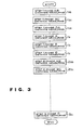
- Fig. 3 is a flow chart illustrating constitution of a conventional software to perform the operation processing of the digital signal.
- the operation from the starting up to the ending is performed during one sampling period.
- sampling means operation to take input data as performed in a digital protective relay, that is, operation to receive analog signal from the PT or CT installed in the power system and to take the instantaneous value at every definite period (for example, at electric angle of 30 degrees in the rated frequency).
- symbols 1ab, 1bc, ..., 3c represent processing of step 1 phase AB distance measuring operation, step 1 phase BC distance measuring operation, ..., step 3 phase C distance measuring operation, respectively.
- the digital distance relay is provided with the distance measuring elements to perform the measurement of steps 1-3 in each of six phases of AB, BC, CA, A, B, C, i.e. total 18 elements.
- the distance measuring operation is repeated 18 times simply in sequence of 1ab, 1bc, ..., 3c corresponding to the 18 distance measuring elements per sampling.
- operation vector E o p and reference vector Ep OL are prepared according to following table. Decision is effected regarding whether or not the phase difference between the operation vector E o p and the reference Ep OL is within 90°, and if it is within 90° the operation signal is outputted.
- the operation time per phase and step is for the operation processing including multiplication and phase difference calculation as above described and therefore becomes relatively long. Consequently, if the total operation processing time should be contained within one sampling period, the sampling period must be made long. As a result the operation finishing time as the distance relay cannot be made fast sufficiently.
- An object of the invention is to provide a digital distance relay which eliminates disadvantages in the prior art and is useful.
- Another object of the invention is to provide a digital distance relay which requires only the distance measuring operation of 2N in number (N: the number of phases on duty) per sampling.
- a digital distance relay as an embodiment of the invention is provided with distance measuring elements of steps 1 to 3 in each of phases on duty among six phases.
- 1t has three means, that is, means for performing the distance measuring operation normally regarding the phase on duty of the third step during each sampling, means for performing the distance measuring operation regarding the phase on duty of the first step during a sampling before the counting finishing of the timer of the second step which begins the counting from the fault inception time detected by the distance measuring operation of the third step, and means for performing the distance measuring operation regarding the phase on duty at the second step during a sampling only after the counting finishing of the timer of the second step.
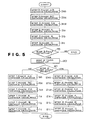
- Fig. 5 shows a flow chart illustrating constitution of software of distance measuring operation in a digital distance relay of the invention.
- operation from the starting of operation up to the ending is performed during one sampling period in similar manner to Fig. 3.
- symbols 1ab, 1bc, ..., 3c represent processing of step 1 phase AB distance measuring operation, step 1 phase BC distance measuring operation, ..., step 3 phase C distance measuring operation, respectively.
- Numeral 19 designates processing of decision whether or not fault detection within the third step by the step 3 distance measuring operation exists, numeral 20 process to count up the timer of the second step, and numeral 21 decision whether or not the timer of the second step finishes the counting.
- the digital relay of the invention is provided with the distance measuring element to perform the measurement of steps 1-3 in each of six phases of AB, BC, CA, A, B, C, i.e. total 18 elements.
- the distance measuring operation regarding phases of AB, BC, CA, A, B, C in the third step is normally performed per sampling in sequence of 3ab, 3bc, ..., 3c shown in the figure. If fault is not detected within the third step, the operation processing in the sampling period is finished.
- the distance measuring operation regarding phases of AB, BC, CA, A, B, C in the first step is performed in sequence of 1 ab, 1 bc, ..., 1c shown in the figure, and the operation processing in the sampling period is finished.
- the distance measuring operation regarding phases of AB, BC, CA, A, B, C in the second step is performed in sequence of 2ab, 2bc, ..., 2c shown in the figure, and the operation processing in the sampling period is finished.
- the distance measuring operation is performed only 6 times per sampling. Even if fault is detected within the third step, the distance measuring operation is performed only 12 times in the third and first steps or the third and second steps.
- Reason of unnecessity of the distance measuring operation in the first step or the second step when fault is not detected within the third step is in that since the detecting range of the distance measuring elements in the third step includes the detecting range of the distance measuring elements in the first step and the second step, if fault is not detected within the third step, it cannot be detected in the first step or the second step.
- the distance measuring operation is performed in the first step and the third step per sampling before the counting finishing of the timer in the second step. Since output of the distance measuring elements in the first step and the third step is used and output of the distance measuring elements in the second step is not used in the directional comparison carrier relay as well known, the operation is sufficient. After the counting finishing of the timer in the second step, function of the directional comparison carrier relay system is stopped thereby the operation is of course sufficient.
- the system of this invention which operates either the first step or the second step, can also be used as it is the directional comparison carrier relay system.
Description
- The present invention relates to digital distance relays with three steps distance protection, and more specifically to a digital distance relay wherein each of N phases on duty among six phases has distance measuring elements in step 1-3, (see for example, Protective Relaying - N. Chernobrovov - MIR publishers - Moscow - chapter XI).
-
- Fig. 1 shows an example of a digital distance relay in the prior art. In Fig. 1, the
digital distance relay 1 receives analog signal being output of a current transformer (hereinafter referred to as "CT") installed ontransmission lines 2 to be protected and a potential transformer (hereinafter referred to as "PT") installed onbus lines 3 connected to thetransmission lines 2 to be protected, and performs the distance measuring operation. - Fig. 2 shows an example of constitution of the digital distance relay, and analog signal from the CT, PT is introduced in an
analog input member 4. Theanalog input member 4 comprises an input transformer 5,filters 6, a sample-and-hold circuit 7 (hereinafter referred to as "SH"), a multiplexer 8, and A-D converter 9 (hereinafter referred to as "AD"), aclock signal generator 10 and the like. Continuous signal inputted in theanalog input member 4 is converted into discrete digital signal. - Next, the digital signal is introduced in a
computer member 11. Thecomputer member 11 comprises a central processing unit 12 (hereinafter referred to as "CPU"), asetting circuit 13 being a sort of a memory to store information for the reach setting of the distance relay and time setting of a timer, a read only memory 14 (hereinafter referred to as "ROM") to store software for the distance measuring operation, a random access memory 15 (hereinafter referred to as "RAM") to store the input signal, the operation result etc., a digital input circuit 16 (hereinafter referred to as "01") being a circuit to introduce external conditions such as a pallet condition of a circuit breaker, a digital output circuit 17 (hereinafter referred to as "DO") for outputting the trip command to the circuit breaker based on the decision result of the relay, and the like. - The digital signal from the
analog input member 4 is transferred to theRAM 15 in thecomputer member 11 by a direct memory access circuit 18 (hereinafter referred to as "DMA"). The CPU f2 performs the operation processing of the digital signal according to the software stored in theROM 14. - Fig. 3 is a flow chart illustrating constitution of a conventional software to perform the operation processing of the digital signal. In Fig. 3, the operation from the starting up to the ending is performed during one sampling period. Here the term "sampling" means operation to take input data as performed in a digital protective relay, that is, operation to receive analog signal from the PT or CT installed in the power system and to take the instantaneous value at every definite period (for example, at electric angle of 30 degrees in the rated frequency).
- In Fig. 3, symbols 1ab, 1bc, ..., 3c represent processing of
step 1 phase AB distance measuring operation,step 1 phase BC distance measuring operation, ...,step 3 phase C distance measuring operation, respectively. - The digital distance relay is provided with the distance measuring elements to perform the measurement of steps 1-3 in each of six phases of AB, BC, CA, A, B, C, i.e. total 18 elements. The distance measuring operation is repeated 18 times simply in sequence of 1ab, 1bc, ..., 3c corresponding to the 18 distance measuring elements per sampling.
- Content of the distance measuring operation varies depending on characteristics of individual distance measuring elements. For example, in the case of mho characteristics shown in Fig. 4, operation vector Eop and reference vector EpOL are prepared according to following table. Decision is effected regarding whether or not the phase difference between the operation vector Eop and the reference EpOL is within 90°, and if it is within 90° the operation signal is outputted.

- Since software of the distance measuring operation in the conventional digital distance relay is constituted as above described, the total operation processing time from the operation starting up to the ending becomes approximately 18 times as large as the operation processing time per phase and step.
- The operation time per phase and step is for the operation processing including multiplication and phase difference calculation as above described and therefore becomes relatively long. Consequently, if the total operation processing time should be contained within one sampling period, the sampling period must be made long. As a result the operation finishing time as the distance relay cannot be made fast sufficiently.
- An object of the invention is to provide a digital distance relay which eliminates disadvantages in the prior art and is useful.
- Another object of the invention is to provide a digital distance relay which requires only the distance measuring operation of 2N in number (N: the number of phases on duty) per sampling.
- Other objects and advantages of the invention will be better understood from the following detailed description of embodiments taken in connection with the accompanying drawings.
- A digital distance relay as an embodiment of the invention is provided with distance measuring elements of
steps 1 to 3 in each of phases on duty among six phases. 1t has three means, that is, means for performing the distance measuring operation normally regarding the phase on duty of the third step during each sampling, means for performing the distance measuring operation regarding the phase on duty of the first step during a sampling before the counting finishing of the timer of the second step which begins the counting from the fault inception time detected by the distance measuring operation of the third step, and means for performing the distance measuring operation regarding the phase on duty at the second step during a sampling only after the counting finishing of the timer of the second step. - Fig. 1 is a systematic diagram showing an example of a power transmission system in which a digital distance relay is used;
- Fig. 2 is a block diagram illustrating constitution of a digital relay;
- Fig. 3 is a flow chart illustrating constitution of software of a digital distance relay in the prior art;
- Fig. 4 is a diagram of mho characteristics; and
- Fig. 5 is a flow chart illustrating constitution of software of distance measuring operation in a digital distance relay as an embodiment of the invention.
- An embodiment of the invention will now be described to the accompanying drawings. Fig. 5 shows a flow chart illustrating constitution of software of distance measuring operation in a digital distance relay of the invention. In Fig. 5, operation from the starting of operation up to the ending is performed during one sampling period in similar manner to Fig. 3.
- In Fig. 5, symbols 1ab, 1bc, ..., 3c represent processing of
step 1 phase AB distance measuring operation,step 1 phase BC distance measuring operation, ...,step 3 phase C distance measuring operation, respectively. Numeral 19 designates processing of decision whether or not fault detection within the third step by thestep 3 distance measuring operation exists,numeral 20 process to count up the timer of the second step, and numeral 21 decision whether or not the timer of the second step finishes the counting. - The digital relay of the invention is provided with the distance measuring element to perform the measurement of steps 1-3 in each of six phases of AB, BC, CA, A, B, C, i.e. total 18 elements. However, according to software stored in the
ROM 14 of thecomputer member 11 as shown in Fig. 5, the distance measuring operation regarding phases of AB, BC, CA, A, B, C in the third step is normally performed per sampling in sequence of 3ab, 3bc, ..., 3c shown in the figure. If fault is not detected within the third step, the operation processing in the sampling period is finished. - If fault is detected within the third step, count up of the timer in the second step is performed in
processing 20, and further decision whether or not the timer of the second step finishes the counting is effected inprocessing 21. - If the timer of the second step does not finish the counting, the distance measuring operation regarding phases of AB, BC, CA, A, B, C in the first step is performed in sequence of 1 ab, 1 bc, ..., 1c shown in the figure, and the operation processing in the sampling period is finished. If the timer of the second step finished the counting, the distance measuring operation regarding phases of AB, BC, CA, A, B, C in the second step is performed in sequence of 2ab, 2bc, ..., 2c shown in the figure, and the operation processing in the sampling period is finished.
- Thus, if fault is not detected within the third step, the distance measuring operation is performed only 6 times per sampling. Even if fault is detected within the third step, the distance measuring operation is performed only 12 times in the third and first steps or the third and second steps.
- Content of the distance measuring operation is similar to that in Fig. 3.
- Reason of unnecessity of the distance measuring operation in the first step or the second step when fault is not detected within the third step is in that since the detecting range of the distance measuring elements in the third step includes the detecting range of the distance measuring elements in the first step and the second step, if fault is not detected within the third step, it cannot be detected in the first step or the second step.
- Reason for the fact that the distance measuring operation of either the first step or the second step may be performed in the same sampling period when fault is detected in the third step is in that the detecting range of the distance measuring elements in the second step includes the detecting range of the distance measuring elements in the first step and if the fault is within the first step the instantaneous operation signal is outputted from the first step before the counting finishing of the timer in the second step thereby the fault is cleared and the distance measuring operation in the second step becomes unnecessary, and that if the fault is within the second step outside the first step the distance measuring operation in the first step is unnecessary.
- Also when the digital relay is used in directional comparison carrier relay system, regarding fault within the third step including faults within the first and second steps, the distance measuring operation is performed in the first step and the third step per sampling before the counting finishing of the timer in the second step. Since output of the distance measuring elements in the first step and the third step is used and output of the distance measuring elements in the second step is not used in the directional comparison carrier relay as well known, the operation is sufficient. After the counting finishing of the timer in the second step, function of the directional comparison carrier relay system is stopped thereby the operation is of course sufficient.
- After all, the system of this invention which operates either the first step or the second step, can also be used as it is the directional comparison carrier relay system.
- Although the embodiment is described in the digital distance relay with six phases of AB, BC, CA, A, B, C all on duty, a digital distance relay with N phases (N = 1-6) being on duty among six phases of AB, BC, CA, A, B, C may be usually used and performs similar effect to that in the embodiment.
- According to the invention as above described, regarding the distance measuring elements in three steps, when fault is not detected within the third step and when faults is detected within the third step, software is constituted so that the distance measuring operation corresponding to two steps at most is performed per sampling, thereby the operation time may be reduced and the sampling period also may be reduced and the digital distance relay has effect of detecting fault at high speed.
Claims (2)
Applications Claiming Priority (2)
| Application Number | Priority Date | Filing Date | Title |
|---|---|---|---|
| JP59233061A JPS61112527A (en) | 1984-11-07 | 1984-11-07 | Digital distance relay |
| JP233061/84 | 1984-11-07 |
Publications (2)
| Publication Number | Publication Date |
|---|---|
| EP0180955A1 EP0180955A1 (en) | 1986-05-14 |
| EP0180955B1 true EP0180955B1 (en) | 1990-01-31 |
Family
ID=16949183
Family Applications (1)
| Application Number | Title | Priority Date | Filing Date |
|---|---|---|---|
| EP85114029A Expired - Lifetime EP0180955B1 (en) | 1984-11-07 | 1985-11-05 | Digital distance relay |
Country Status (4)
| Country | Link |
|---|---|
| US (1) | US4689709A (en) |
| EP (1) | EP0180955B1 (en) |
| JP (1) | JPS61112527A (en) |
| AU (1) | AU575442B2 (en) |
Families Citing this family (9)
| Publication number | Priority date | Publication date | Assignee | Title |
|---|---|---|---|---|
| JPS61112527A (en) * | 1984-11-07 | 1986-05-30 | 三菱電機株式会社 | Digital distance relay |
| SE451102B (en) * | 1985-12-20 | 1987-08-31 | Asea Ab | PROCEDURE FOR DETECTING HOGRESISTIVE EARTH ERROR ON A POWER PIPE LOCATED BETWEEN TWO STATIONS AND THE DEVICE FOR IMPLEMENTATION OF THE PRESENT PROCEDURE |
| SE449796B (en) * | 1985-12-20 | 1987-05-18 | Asea Ab | PROCEDURE AND DEVICE FOR LOCATION OF ERRORS ON A POWER CORD |
| US4812995A (en) * | 1987-05-19 | 1989-03-14 | Girgis Adly A | Adaptive Kalman Filtering in fault classification |
| US5216621A (en) * | 1991-02-28 | 1993-06-01 | Mehta Tech. Inc. | Line disturbance monitor and recorder system |
| WO1995024014A2 (en) * | 1994-02-28 | 1995-09-08 | Abb Power T & D Company Inc. | One-terminal data fault location system |
| US5790418A (en) * | 1995-10-17 | 1998-08-04 | Schweitzer Engineering Laboratories, Inc. | Adaptive polarizing memory voltage time constant |
| US8340931B2 (en) * | 2009-10-05 | 2012-12-25 | Mehta Tech, Inc. | Power grid with comparison of differences in remote phasor changes |
| CN102437556B (en) * | 2011-08-04 | 2013-11-27 | 天津大学 | Sequence component longitudinal direction protection method of six-phase power transmission line |
Family Cites Families (6)
| Publication number | Priority date | Publication date | Assignee | Title |
|---|---|---|---|---|
| US4261038A (en) * | 1978-02-28 | 1981-04-07 | National Research Development Corporation | Protection of electrical power supply systems |
| JPS55127829A (en) * | 1979-03-27 | 1980-10-03 | Tokyo Shibaura Electric Co | Digital distance relay unit |
| US4377833A (en) * | 1981-08-17 | 1983-03-22 | Electric Power Research Institute, Inc. | Methods and apparatus for protecting electrical reactors |
| JPS5854825A (en) * | 1981-09-29 | 1983-03-31 | 株式会社東芝 | Protective relay unit |
| JPS6039312A (en) * | 1983-08-10 | 1985-03-01 | 株式会社東芝 | Protective relaying device |
| JPS61112527A (en) * | 1984-11-07 | 1986-05-30 | 三菱電機株式会社 | Digital distance relay |
-
1984
- 1984-11-07 JP JP59233061A patent/JPS61112527A/en active Granted
-
1985
- 1985-11-05 EP EP85114029A patent/EP0180955B1/en not_active Expired - Lifetime
- 1985-11-06 US US06/795,449 patent/US4689709A/en not_active Expired - Lifetime
- 1985-11-06 AU AU49385/85A patent/AU575442B2/en not_active Ceased
Non-Patent Citations (1)
| Title |
|---|
| Protective Relaying. N. CHERNOBROVOV (MIR-Moscow) * |
Also Published As
| Publication number | Publication date |
|---|---|
| JPS61112527A (en) | 1986-05-30 |
| US4689709A (en) | 1987-08-25 |
| AU575442B2 (en) | 1988-07-28 |
| AU4938585A (en) | 1986-05-15 |
| EP0180955A1 (en) | 1986-05-14 |
| JPH0519377B2 (en) | 1993-03-16 |
Similar Documents
| Publication | Publication Date | Title |
|---|---|---|
| US4402028A (en) | Protective relay methods and apparatus | |
| US3984737A (en) | Protective relaying system | |
| EP0384435B1 (en) | Power signal processing system | |
| US4825326A (en) | Digital calculation type differential relay | |
| KR0133658B1 (en) | Static trip device for a circuit breaker protecting a three | |
| US4272816A (en) | Overcurrent protecting apparatus | |
| Eissa et al. | A novel digital distance relaying technique for transmission line protection | |
| CA2387811A1 (en) | Improved restraint-type differential relay | |
| US5783946A (en) | Fault type classification algorithm | |
| EP0180955B1 (en) | Digital distance relay | |
| US4377833A (en) | Methods and apparatus for protecting electrical reactors | |
| US5808845A (en) | System for preventing sympathetic tripping in a power system | |
| EP1383219B1 (en) | Distance relay apparatus | |
| EP0322518B1 (en) | Digital protective relay | |
| EP0224749B1 (en) | Digital fault locator | |
| US5793595A (en) | Multi-application relay for power systems | |
| US4943766A (en) | Electric quantity detecting method | |
| US4314301A (en) | Protective relaying devices | |
| CA2427821C (en) | Current compensation method and device for power system protection | |
| US7206177B2 (en) | Device and method for protection against overcurrents in an electrical energy distribution cabinet | |
| RU48240U1 (en) | RELAY PROTECTION AND AUTOMATION | |
| US20240072697A1 (en) | Split-phase protection of generators | |
| JPS6318408B2 (en) | ||
| CA1200594A (en) | Protective relay methods and apparatus | |
| SU1728914A1 (en) | Device for back-up phase-fault current protection of tapped line with single-end feeding |
Legal Events
| Date | Code | Title | Description |
|---|---|---|---|
| PUAI | Public reference made under article 153(3) epc to a published international application that has entered the european phase |
Free format text: ORIGINAL CODE: 0009012 |
|
| AK | Designated contracting states |
Kind code of ref document: A1 Designated state(s): CH GB LI SE |
|
| 17P | Request for examination filed |
Effective date: 19860702 |
|
| 17Q | First examination report despatched |
Effective date: 19880217 |
|
| GRAA | (expected) grant |
Free format text: ORIGINAL CODE: 0009210 |
|
| AK | Designated contracting states |
Kind code of ref document: B1 Designated state(s): CH GB LI SE |
|
| PLBE | No opposition filed within time limit |
Free format text: ORIGINAL CODE: 0009261 |
|
| STAA | Information on the status of an ep patent application or granted ep patent |
Free format text: STATUS: NO OPPOSITION FILED WITHIN TIME LIMIT |
|
| 26N | No opposition filed | ||
| EAL | Se: european patent in force in sweden |
Ref document number: 85114029.3 |
|
| REG | Reference to a national code |
Ref country code: GB Ref legal event code: 746 Effective date: 19951026 |
|
| REG | Reference to a national code |
Ref country code: GB Ref legal event code: 747B |
|
| REG | Reference to a national code |
Ref country code: GB Ref legal event code: 747 |
|
| REG | Reference to a national code |
Ref country code: GB Ref legal event code: 747C |
|
| PGFP | Annual fee paid to national office [announced via postgrant information from national office to epo] |
Ref country code: SE Payment date: 19981105 Year of fee payment: 14 |
|
| PGFP | Annual fee paid to national office [announced via postgrant information from national office to epo] |
Ref country code: GB Payment date: 19981106 Year of fee payment: 14 |
|
| PGFP | Annual fee paid to national office [announced via postgrant information from national office to epo] |
Ref country code: CH Payment date: 19981120 Year of fee payment: 14 |
|
| PG25 | Lapsed in a contracting state [announced via postgrant information from national office to epo] |
Ref country code: GB Free format text: LAPSE BECAUSE OF NON-PAYMENT OF DUE FEES Effective date: 19991105 |
|
| PG25 | Lapsed in a contracting state [announced via postgrant information from national office to epo] |
Ref country code: SE Free format text: LAPSE BECAUSE OF NON-PAYMENT OF DUE FEES Effective date: 19991106 |
|
| PG25 | Lapsed in a contracting state [announced via postgrant information from national office to epo] |
Ref country code: LI Free format text: LAPSE BECAUSE OF NON-PAYMENT OF DUE FEES Effective date: 19991130 Ref country code: CH Free format text: LAPSE BECAUSE OF NON-PAYMENT OF DUE FEES Effective date: 19991130 |
|
| GBPC | Gb: european patent ceased through non-payment of renewal fee |
Effective date: 19991105 |
|
| REG | Reference to a national code |
Ref country code: CH Ref legal event code: PL |
|
| EUG | Se: european patent has lapsed |
Ref document number: 85114029.3 |