EP0180355A2 - Abgeschrecktes katalytisches Krackverfahren - Google Patents
Abgeschrecktes katalytisches Krackverfahren Download PDFInfo
- Publication number
- EP0180355A2 EP0180355A2 EP85307242A EP85307242A EP0180355A2 EP 0180355 A2 EP0180355 A2 EP 0180355A2 EP 85307242 A EP85307242 A EP 85307242A EP 85307242 A EP85307242 A EP 85307242A EP 0180355 A2 EP0180355 A2 EP 0180355A2
- Authority
- EP
- European Patent Office
- Prior art keywords
- catalyst
- reactor
- steam
- riser
- quench
- Prior art date
- Legal status (The legal status is an assumption and is not a legal conclusion. Google has not performed a legal analysis and makes no representation as to the accuracy of the status listed.)
- Granted
Links
- 238000000034 method Methods 0.000 title claims abstract description 20
- 230000008569 process Effects 0.000 title claims abstract description 19
- 238000004523 catalytic cracking Methods 0.000 title claims description 6
- 238000010791 quenching Methods 0.000 claims abstract description 56
- 229930195733 hydrocarbon Natural products 0.000 claims abstract description 18
- 150000002430 hydrocarbons Chemical class 0.000 claims abstract description 18
- 238000005336 cracking Methods 0.000 claims abstract description 14
- XLYOFNOQVPJJNP-UHFFFAOYSA-N water Substances O XLYOFNOQVPJJNP-UHFFFAOYSA-N 0.000 claims abstract description 10
- 230000003197 catalytic effect Effects 0.000 claims abstract description 3
- 239000003054 catalyst Substances 0.000 claims description 107
- 239000004215 Carbon black (E152) Substances 0.000 claims description 13
- 238000004227 thermal cracking Methods 0.000 claims description 12
- 230000000171 quenching effect Effects 0.000 claims description 8
- 230000006872 improvement Effects 0.000 claims description 5
- 230000035484 reaction time Effects 0.000 claims description 3
- 238000007599 discharging Methods 0.000 claims 1
- 230000000063 preceeding effect Effects 0.000 claims 1
- 230000007423 decrease Effects 0.000 abstract description 4
- 239000000047 product Substances 0.000 description 32
- 239000012071 phase Substances 0.000 description 17
- 238000006243 chemical reaction Methods 0.000 description 11
- 239000003502 gasoline Substances 0.000 description 11
- 230000000694 effects Effects 0.000 description 10
- 230000009467 reduction Effects 0.000 description 10
- 238000000926 separation method Methods 0.000 description 10
- JTJMJGYZQZDUJJ-UHFFFAOYSA-N phencyclidine Chemical class C1CCCCN1C1(C=2C=CC=CC=2)CCCCC1 JTJMJGYZQZDUJJ-UHFFFAOYSA-N 0.000 description 9
- 239000000571 coke Substances 0.000 description 8
- 239000003921 oil Substances 0.000 description 8
- 238000010793 Steam injection (oil industry) Methods 0.000 description 7
- 230000009286 beneficial effect Effects 0.000 description 7
- 230000008859 change Effects 0.000 description 7
- 239000010771 distillate fuel oil Substances 0.000 description 6
- 239000000295 fuel oil Substances 0.000 description 5
- 239000007789 gas Substances 0.000 description 5
- 238000001816 cooling Methods 0.000 description 4
- 238000013461 design Methods 0.000 description 4
- 238000004519 manufacturing process Methods 0.000 description 4
- 239000000463 material Substances 0.000 description 4
- 238000011027 product recovery Methods 0.000 description 4
- 230000008901 benefit Effects 0.000 description 3
- 238000005094 computer simulation Methods 0.000 description 3
- 239000000203 mixture Substances 0.000 description 3
- 239000012808 vapor phase Substances 0.000 description 3
- 239000010457 zeolite Substances 0.000 description 3
- 229910021536 Zeolite Inorganic materials 0.000 description 2
- PNEYBMLMFCGWSK-UHFFFAOYSA-N aluminium oxide Inorganic materials [O-2].[O-2].[O-2].[Al+3].[Al+3] PNEYBMLMFCGWSK-UHFFFAOYSA-N 0.000 description 2
- 238000013459 approach Methods 0.000 description 2
- HNPSIPDUKPIQMN-UHFFFAOYSA-N dioxosilane;oxo(oxoalumanyloxy)alumane Chemical compound O=[Si]=O.O=[Al]O[Al]=O HNPSIPDUKPIQMN-UHFFFAOYSA-N 0.000 description 2
- 229910052751 metal Inorganic materials 0.000 description 2
- 239000002184 metal Substances 0.000 description 2
- 150000002739 metals Chemical class 0.000 description 2
- 230000005501 phase interface Effects 0.000 description 2
- 238000012546 transfer Methods 0.000 description 2
- MXRIRQGCELJRSN-UHFFFAOYSA-N O.O.O.[Al] Chemical compound O.O.O.[Al] MXRIRQGCELJRSN-UHFFFAOYSA-N 0.000 description 1
- VYPSYNLAJGMNEJ-UHFFFAOYSA-N Silicium dioxide Chemical compound O=[Si]=O VYPSYNLAJGMNEJ-UHFFFAOYSA-N 0.000 description 1
- 229940058905 antimony compound for treatment of leishmaniasis and trypanosomiasis Drugs 0.000 description 1
- 150000001463 antimony compounds Chemical class 0.000 description 1
- 229910002091 carbon monoxide Inorganic materials 0.000 description 1
- 238000004939 coking Methods 0.000 description 1
- 238000002485 combustion reaction Methods 0.000 description 1
- 230000007797 corrosion Effects 0.000 description 1
- 238000005260 corrosion Methods 0.000 description 1
- 238000005520 cutting process Methods 0.000 description 1
- 230000003247 decreasing effect Effects 0.000 description 1
- 238000011161 development Methods 0.000 description 1
- 230000018109 developmental process Effects 0.000 description 1
- 238000006073 displacement reaction Methods 0.000 description 1
- 238000002347 injection Methods 0.000 description 1
- 239000007924 injection Substances 0.000 description 1
- 238000009533 lab test Methods 0.000 description 1
- 239000007788 liquid Substances 0.000 description 1
- 239000012263 liquid product Substances 0.000 description 1
- 239000011159 matrix material Substances 0.000 description 1
- 238000012986 modification Methods 0.000 description 1
- 230000004048 modification Effects 0.000 description 1
- TVMXDCGIABBOFY-UHFFFAOYSA-N octane Chemical compound CCCCCCCC TVMXDCGIABBOFY-UHFFFAOYSA-N 0.000 description 1
- 230000003647 oxidation Effects 0.000 description 1
- 238000007254 oxidation reaction Methods 0.000 description 1
- 229910052763 palladium Inorganic materials 0.000 description 1
- 238000002161 passivation Methods 0.000 description 1
- 229910052697 platinum Inorganic materials 0.000 description 1
- 229910052761 rare earth metal Inorganic materials 0.000 description 1
- 150000002910 rare earth metals Chemical group 0.000 description 1
- 230000008929 regeneration Effects 0.000 description 1
- 238000011069 regeneration method Methods 0.000 description 1
- 239000003079 shale oil Substances 0.000 description 1
- 230000035939 shock Effects 0.000 description 1
- 238000004088 simulation Methods 0.000 description 1
- 238000002791 soaking Methods 0.000 description 1
- 239000000243 solution Substances 0.000 description 1
- 238000003756 stirring Methods 0.000 description 1
- 238000004781 supercooling Methods 0.000 description 1
- 238000009834 vaporization Methods 0.000 description 1
- 230000008016 vaporization Effects 0.000 description 1
- 239000002918 waste heat Substances 0.000 description 1
Images
Classifications
-
- C—CHEMISTRY; METALLURGY
- C10—PETROLEUM, GAS OR COKE INDUSTRIES; TECHNICAL GASES CONTAINING CARBON MONOXIDE; FUELS; LUBRICANTS; PEAT
- C10G—CRACKING HYDROCARBON OILS; PRODUCTION OF LIQUID HYDROCARBON MIXTURES, e.g. BY DESTRUCTIVE HYDROGENATION, OLIGOMERISATION, POLYMERISATION; RECOVERY OF HYDROCARBON OILS FROM OIL-SHALE, OIL-SAND, OR GASES; REFINING MIXTURES MAINLY CONSISTING OF HYDROCARBONS; REFORMING OF NAPHTHA; MINERAL WAXES
- C10G11/00—Catalytic cracking, in the absence of hydrogen, of hydrocarbon oils
- C10G11/14—Catalytic cracking, in the absence of hydrogen, of hydrocarbon oils with preheated moving solid catalysts
- C10G11/18—Catalytic cracking, in the absence of hydrogen, of hydrocarbon oils with preheated moving solid catalysts according to the "fluidised-bed" technique
Definitions
- the fluidized catalytic cracking, or FCC, process is one of the work horses of modem refineries.
- hot catalyst contacts a relatively heavy oil feed, producing coked catalyst and cracked products.
- the coked catalyst is regenerated by burning the coke from coked catalyst in a regenerator.
- the catalyst is heated during the regeneration, because the coke bums.
- the hot regenerated catalyst is recycled to contact more heavy oil feed.
- refiners have attempted to maximize riser cracking, and minimize dense bed cracking. Generally this has been done by extending the catalyst riser and cutting down on the amount of catalyst inventory in the relatively large vessel into which the riser reactor discharged.
- Some FCC units have attempted to practically eliminate dense bed cracking, by causing the riser reactor to discharge into a rough cut cyclone, or to discharge down toward the dense bed without agitating it, whereby substantial separation of cracked products from deactivated catalyst can be quickly obtained. Such an approach is shown in U.S. 3,785.962.
- U.S. 4 ,072,600 disclosed adding Pt, Pd, etc. to the circulating catalyst inventory to promote afterbuming of CO to CO 2 in the FCC regenerator.
- the present invention provides an improved FCC process wherein a conventional fluidizable catalytic cracking catalyst and a hydrocarbon feed are charged to a reactor riser at catalytic riser cracking conditions to form catalytically cracked vapor product and spent catalyst which are discharged into a reactor vessel via a riser reactor outlet connective with a separation means to produce a catalyst lean phase comprising a majority of said cracked product, and a catalyst rich phase comprising a majority of said spent catalyst, is discharged into a dense bed of catalyst maintained below said riser outlet and said catalyst lean phase is discharged into said vessel and then withdrawn from said vessel via a vessel outlet, the improvement comprising addition of a quenching stream into said vessel above said dense bed of catalyst
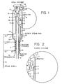
- Figure 1 shows an FCC riser reactor with quench steam ring.
- Figure 2 shows a detail of an FCC reactor with a closed cyclone configuration and quench steam ring installed.
- any conventional feed to an FCC unit can be used.
- the feed to an FCC unit comprises gas oils, vacuum gas oils, topped crudes, etc.
- Heavy feeds, such as tar sands, shale oil, and asphaltic fractions may be used, if the unit can tolerate the high metals concentrations and coking tendencies of these feeds.
- the present invention is not the discovery of a new feed to an FCC unit, but a way to make better use of feeds now used for FCC units.
- any catalyst suitable for use in an FCC unit can be used in the process of the present invention.
- the catalyst is one of the many commercially available zeolite based catalysts, but it is also possible to obtain benefits from practicing the present invention when amorphous materials such as alumina, or amorphous silica/alumina are used as the catalyst.
- Especially preferred catalysts are rare earth exchanged Y zeolites in an amorphous matrix.
- the catalyst may contain one or more of the following types of promoters.
- the present invention helps FCC units operating with conventional catalyst to operate more efficiently.
- the riser reactor discharges directly into a rough cut cyclone, or other separation means, whereby a very quick separation of cracked products from catalyst may be contained.
- the riser reactor discharge down into the dense bed reactor, from a relatively high distance above the dense bed catalyst level. This minimizes stirring up of the dense bed, and minimizes contact of cracked products/catalyst.
- the riser reactor discharges directly into a dense bed of catalyst, either in a vertical up direction, or horizontally. Such an operation tends to promote dense bed cracking, and should be avoided.
- Many older FCC units were built at a time when dense bed cracking was more highly regarded, and it is not possible to economically change the configuration of the units. It is harder to see the benefits of the present invention in such units, because a lot of hot catalyst is tossed about within the vessel containing the dense bed of catalyst, minimizing the temperature quenching effect of the steam quench.
- the preferred riser reactor provides a residence time of less than 10 seconds, preferably on the order of 1-5 seconds, and it discharges directly into a rough cut cyclone to effect rapid separation of cracked products from catalyst.
- the riser reactor may operate in upflow, or downflow, though an upflow riser reactor is preferred because there is much more operating experience available for such a unit
- the riser reactor may actually be two or more reactors in series, or in parallel. Although such riser reactor designs are contemplated for use herein, they form no part of the present invention.
- the riser reactor discharges into a vessel designed to contain a dense bed of catalyst.
- Conventional FCC dense bed reactor designs call for a rela- tivety large vessel, usually several orders of magnitude larger in volume than the riser reactor, which serves to collect spent catalyst in the lower portion of the reactor.
- the spent catalyst is withdrawn from the bottom of the reactor, usually through a stripper zone containing baffles, and removed from the reactor. Stripping steam is added at the bottom of the reactor vessel to displace easily strippable hydrocarbons from the spent catalyst, so that these etrip- pable hydrocarbons will not be burned in the regenerator.
- Any conventional FCC regenerator may be used in conjunction with the present invention.
- CO afterbuming regenerators are, in most situations, preferred as far as maximum efficiency in the total FCC unit is concerned, however the present invention will work equally well with CO afterbuming and non-CO afterbuming regenerators.
- the regenerator is an essential portion of an FCC unit, but the regenerator section, by itself, forms no portion of the present invention.
- An especially effective regenerator design is a stacked regenerator with a first dense bed, or coke combustor, a dilute phase transport riser and a second dense bed of hot regenerated catalyst maintained generally above the coke combustor.
- one or more quench means are disposed within the reactor vessel into which the riser reactor discharges. Steam is the preferred quenching medium. Steam is preferably admitted via a radially disposed steam injection ring disposed just above the dense bed of catalyst
- the function of the steam quench is twofold. It reduces the temperature of the cracked products in the vapor phase above the dense bed of catalyst. It also displaces the cracked hydrocarbons from the reactor vessel, thereby decreasing the residence time of these materials in the reactor vessel.
- the amount of steam quench injected, and the precise location of the steam quench injection point within the vessel containing the dense bed of spent catalyst, will determine the change in residence time of cracked vapors within the reactor.
- the temperature, and amount of steam qt!r - sh will determine the temperature change of cracked product within the reactor.
- the temperature of the steam will have a significant effect on the quenching effect, or temperature reduction of cracked products. It is also possible to simply add water and let the water vaporize within the reactor, or provide enough surface area in the steam quench ring so that the water will vaporize and become steam before entering the reactor. This would give maximum cooling per weight of water added, the cooling effect being vaporization of water to steam, followed by an increase in sensible heat of the steam produced.
- the riser reactor discharges into a primary cyclone, which makes a rough, but fairly effective, separation of catalyst from cracked products.
- the vapor from the primary cyclone is discharged directly into a secondary cyclone which is able to effect a far more complete separation of catalyst from cracked products than could be achieved in the rough cut cyclone attached directly to the riser reactor outlet
- the extent of undesirable thermal cracking that goes on in a reactor may be estimated by calculating the residence time in the reactor at a given temperature. These two numbers can be used to devise an ERT or Equivalent Reaction Time at 427°C (800°F). More details about ERT are provided in U.S. 4,379,747 and U.S. 4,428,824. Another way of evaluating relative reaction velocities in thermal cracking is to compare S.F. or Soaking Factors. By definition, the ERT and SF are 1 .0 at 427°C (800°F). As the temperature increases, the reaction rate increases, to 2.0 at 439°C (822°F), and so on.
- the amount of thermal cracking will be cut about in half by reducing the residence time of the catalytically cracked product by one half, or by reducing the vapor temperature from 439 to 427°C (822 to 800°F), or some combination of these.
- the amount of quench added should be sufficient to reduce thermal cracking enough to increase the yield of gasoline and light fuel oil products at least 1/2%, and preferably 1 to 2%, or more.
- reactor riser 4 is in actuality the reactor where well over 90 percent of the desired catalytic cracking reactions occur. Ideally, 1 00 percent of the reactions would take place in reactor riser 4, and no reaction whatever would take place in reactor 1 .
- refiners may revise their vocabulary to refer to riser 4 as the reactor, and vessel 1 as a spent catalyst/cracked product separation means, but such usage would be confusing to those skilled in the FCC arts.
- Dense bed 20, with upper surface or interface level 17 is the collection of catalyst from the diplegs of the cyclones within reactor 1.
- the dense bed/dilute phase interface 17 may be below the catalyst diplegs, as shown in the drawing, or the dense bed level may be raised, or the diplegs extended, so that the diplegs are immersed within the dense bed of catalyst 20.
- the spent catalyst which collects as dense bed 20 in the bottom of reactor 1 is subjected to stripping to remove easily strippable hydrocarbon vapors from the spent catalyst before it is sent to a catalyst regenerator, not shown.
- This steam stripping of spent catalyst which is conventional, is conducted at reactor stripper 21.
- a steam supply, shown as line 30, admits steam via either line 22 and/or 24 to lower and upper stripper steam rings, respectively.
- inlet 5 to cyclone 6 would resemble an inverted funnel which was radially aligned with, and above outlet. 3 of primary cyclone 2, as shown in Figure 2.
- closed cyclones Such a configuration is not, strictly speaking, "closed”, because it is still possible, and very desirable, for cracked hydrocarbon products, and quench steam, to enter inlet 5 in the annular space between outlet 3 and inlet 5.
- cracked vapor and quench steam and stripping steam to eventually enter the outlet plenum 14, and the closed cyclone modification described above works very well in this service.
- it is beneficial io immerse dipleg 12 about 50 cm past the dense bed/dilute phase interface 17. This minimizes leakage of vapors down dipleg 12, as the catalyst seals the outlet of dipleg 12.
- a characteristic of "closed cyclone" configuration is that 90% of the cracked vapor product will pass from the primary cyclone outlet and enter the secondary cyclone inlet in less than 1 second, preferably in less than 1/2 second.
- Quench steam ring 27 shown in the drawing would reduce the residence time of cracked products in space 15, but would do little or nothing towards reducing the temperature of the cracked products, because of the large amount of hot spent catalyst present. In such a circumstance, it may be beneficial to move the quench steam ring to an elevation equal to, or slightly above the reactor riser outlet, so that steam quench will have a noticeable cooling effect on reactor vapors. In some circumstances, a combination of steam quench via quench ring 27 shown in the drawing and another quench ring located above the riser reactor outlet, and not shown in the drawing, would be beneficial.
- the two illustrative embodiments which follow do not represent commercial or laboratory tests. They are based on computer simulations of commercial operation, and are believed to be accurate predictors of what will happen in commercial operation.
- the feedstock used was similar to the Joliet Sour Heavy Gas Oil described hereafter.
- reactor vessel temperature refers to the vapor outlet temperature, measured at the top of the reactor. The reason the reactor vessel temperature did not change much was because in the open cyclone configuration, corresponding roughly to the one shown in the drawing, the steam is in contact with significant amounts of hydrocarbon exiting the vessel and some catalyst.
- the reduction in vapor residence time in the dilute phase portion of reactor vessel 1 is estimated to be about 10-15%, or a reduction of about 4 to 6 seconds residence time.
- reactor vessel temperature refers to the temperature at the top of the reactor vessel, which is not the same thing as the temperature of the vapor leaving the reactor.
- the vapor leaving the unquenched reactor would have a temperature of about 535.0°C (995°F).
- the supercooling of the reactor vessel dilute phase temperature by quench steam was due to the fact that the closed cyclone configuration resulted ir significantly less cked vapor and entrained catalyst being discharged into the dilute phase within reactor vessel 1.
- the quench steam was far more effective in cooling down this greatly reduced weight of material, in the dosed cyclone configuration case, than when the quench steam was being inundated by vast amounts of cracked vapors and spent catalyst, as in the open cyclone configuration discussed in conjunction with Table III.
Landscapes
- Chemical & Material Sciences (AREA)
- Oil, Petroleum & Natural Gas (AREA)
- Engineering & Computer Science (AREA)
- Chemical Kinetics & Catalysis (AREA)
- General Chemical & Material Sciences (AREA)
- Organic Chemistry (AREA)
- Production Of Liquid Hydrocarbon Mixture For Refining Petroleum (AREA)
- Devices And Processes Conducted In The Presence Of Fluids And Solid Particles (AREA)
Applications Claiming Priority (2)
| Application Number | Priority Date | Filing Date | Title |
|---|---|---|---|
| US66653384A | 1984-10-30 | 1984-10-30 | |
| US666533 | 1984-10-30 |
Publications (3)
| Publication Number | Publication Date |
|---|---|
| EP0180355A2 true EP0180355A2 (de) | 1986-05-07 |
| EP0180355A3 EP0180355A3 (en) | 1986-07-02 |
| EP0180355B1 EP0180355B1 (de) | 1989-04-05 |
Family
ID=24674462
Family Applications (1)
| Application Number | Title | Priority Date | Filing Date |
|---|---|---|---|
| EP85307242A Expired EP0180355B1 (de) | 1984-10-30 | 1985-10-10 | Abgeschrecktes katalytisches Krackverfahren |
Country Status (6)
| Country | Link |
|---|---|
| EP (1) | EP0180355B1 (de) |
| JP (1) | JPS61113686A (de) |
| AU (1) | AU586985B2 (de) |
| DE (1) | DE3569261D1 (de) |
| ES (1) | ES8609440A1 (de) |
| ZA (1) | ZA857398B (de) |
Cited By (6)
| Publication number | Priority date | Publication date | Assignee | Title |
|---|---|---|---|---|
| US4793915A (en) * | 1987-01-15 | 1988-12-27 | Mobil Oil Corporation | Short contact time fluid catalytic cracking process |
| US4909993A (en) * | 1984-05-21 | 1990-03-20 | Mobil Oil Corporation | Closed cyclone FCC catalyst separation apparatus |
| US5039397A (en) * | 1984-05-21 | 1991-08-13 | Mobil Oil Corporation | Closed cyclone FCC catalyst separation method and apparatus |
| GB2242438A (en) * | 1990-03-26 | 1991-10-02 | Amoco Corp | Catalytic cracking with quenching |
| US5055177A (en) * | 1984-05-21 | 1991-10-08 | Mobil Oil Corporation | Closed cyclone FCC catalyst separation method and apparatus |
| US6482312B1 (en) | 1987-08-11 | 2002-11-19 | Stone & Webster Process Technology, Inc. | Particulate solids cracking apparatus and process |
Family Cites Families (5)
| Publication number | Priority date | Publication date | Assignee | Title |
|---|---|---|---|---|
| US4043899A (en) * | 1976-02-27 | 1977-08-23 | Mobil Oil Corporation | Method and means for separating gasiform materials from finely divided catalyst particles |
| US4043893A (en) * | 1976-03-31 | 1977-08-23 | Erico Products, Inc. | Electrical contact |
| US4194965A (en) * | 1978-02-02 | 1980-03-25 | Mobil Oil Corporation | Fluid catalytic cracking |
| US4478708A (en) * | 1983-10-11 | 1984-10-23 | Farnsworth Carl D | Method and apparatus for separating fluidized solid particles suspended in gasiform material |
| US4555328A (en) * | 1984-01-19 | 1985-11-26 | Mobil Oil Corporation | Method and apparatus for injecting liquid hydrocarbon feed and steam into a catalytic cracking zone |
-
1985
- 1985-09-25 ZA ZA857398A patent/ZA857398B/xx unknown
- 1985-10-01 AU AU48167/85A patent/AU586985B2/en not_active Expired - Fee Related
- 1985-10-10 EP EP85307242A patent/EP0180355B1/de not_active Expired
- 1985-10-10 DE DE8585307242T patent/DE3569261D1/de not_active Expired
- 1985-10-28 ES ES548260A patent/ES8609440A1/es not_active Expired
- 1985-10-30 JP JP60241770A patent/JPS61113686A/ja active Pending
Cited By (7)
| Publication number | Priority date | Publication date | Assignee | Title |
|---|---|---|---|---|
| US4909993A (en) * | 1984-05-21 | 1990-03-20 | Mobil Oil Corporation | Closed cyclone FCC catalyst separation apparatus |
| US5039397A (en) * | 1984-05-21 | 1991-08-13 | Mobil Oil Corporation | Closed cyclone FCC catalyst separation method and apparatus |
| US5055177A (en) * | 1984-05-21 | 1991-10-08 | Mobil Oil Corporation | Closed cyclone FCC catalyst separation method and apparatus |
| US4793915A (en) * | 1987-01-15 | 1988-12-27 | Mobil Oil Corporation | Short contact time fluid catalytic cracking process |
| US6482312B1 (en) | 1987-08-11 | 2002-11-19 | Stone & Webster Process Technology, Inc. | Particulate solids cracking apparatus and process |
| GB2242438A (en) * | 1990-03-26 | 1991-10-02 | Amoco Corp | Catalytic cracking with quenching |
| GB2242438B (en) * | 1990-03-26 | 1994-10-26 | Amoco Corp | Catalytic cracking with quenching |
Also Published As
| Publication number | Publication date |
|---|---|
| ZA857398B (en) | 1987-05-27 |
| ES8609440A1 (es) | 1986-09-01 |
| AU4816785A (en) | 1986-05-08 |
| EP0180355B1 (de) | 1989-04-05 |
| EP0180355A3 (en) | 1986-07-02 |
| AU586985B2 (en) | 1989-08-03 |
| JPS61113686A (ja) | 1986-05-31 |
| ES548260A0 (es) | 1986-09-01 |
| DE3569261D1 (en) | 1989-05-11 |
Similar Documents
| Publication | Publication Date | Title |
|---|---|---|
| US3909392A (en) | Fluid catalytic cracking process with substantially complete combustion of carbon monoxide during regeneration of catalyst | |
| CA1156591A (en) | Method for two stage catalyst regeneration | |
| CA1156592A (en) | Method and apparatus for cracking residual oils | |
| JP4656689B2 (ja) | 流動触媒転換のためのライザ反応器 | |
| US5372704A (en) | Cracking with spent catalyst | |
| US4978440A (en) | Quenched catalytic cracking process | |
| US4297203A (en) | Apparatus for the catalytic cracking of hydrocarbons | |
| JP4361234B2 (ja) | ディーゼル油の収率と液化ガスの収率を同時に増加させる接触分解法 | |
| US4574044A (en) | Method for spent catalyst treating for fluidized catalytic cracking systems | |
| US3907663A (en) | Conversion of hydrocarbons | |
| US5043058A (en) | Quenching downstream of an external vapor catalyst separator | |
| CA1119116A (en) | Method and apparatus for regenerating a fluid cracking catalyst | |
| US20150152027A1 (en) | Integrated solvent-deasphalting and fluid catalytic cracking process for light olefin production | |
| CN110724553B (zh) | 一种采用稀相输送床与快速流化床进行催化裂解的方法和系统 | |
| US3448037A (en) | Cracking with crystalline zeolite catalyst | |
| Avidan | Origin, development and scope of FCC catalysis | |
| US5215650A (en) | Cooling exothermic regenerator with endothermic reactions | |
| CA1168613A (en) | Use of naphtha in carbo-metallic oil conversion | |
| US5073249A (en) | Heavy oil catalytic cracking process and apparatus | |
| US4738829A (en) | Apparatus for spent catalyst treating for fluidized catalytic cracking systems | |
| CA1125688A (en) | Fluid catalytic cracking | |
| EP0180355B1 (de) | Abgeschrecktes katalytisches Krackverfahren | |
| US5089235A (en) | Catalytic cracking unit with external cyclone and oil quench system | |
| US4869807A (en) | Gasoline octane enhancement in fluid catalytic cracking process with split feed injection to riser reactor | |
| US5087427A (en) | Catalytic cracking unit with internal gross cut separator and quench injector |
Legal Events
| Date | Code | Title | Description |
|---|---|---|---|
| PUAI | Public reference made under article 153(3) epc to a published international application that has entered the european phase |
Free format text: ORIGINAL CODE: 0009012 |
|
| AK | Designated contracting states |
Kind code of ref document: A2 Designated state(s): BE DE FR GB IT NL |
|
| PUAL | Search report despatched |
Free format text: ORIGINAL CODE: 0009013 |
|
| AK | Designated contracting states |
Kind code of ref document: A3 Designated state(s): BE DE FR GB IT NL |
|
| 17P | Request for examination filed |
Effective date: 19861011 |
|
| 17Q | First examination report despatched |
Effective date: 19871112 |
|
| GRAA | (expected) grant |
Free format text: ORIGINAL CODE: 0009210 |
|
| AK | Designated contracting states |
Kind code of ref document: B1 Designated state(s): BE DE FR GB IT NL |
|
| REF | Corresponds to: |
Ref document number: 3569261 Country of ref document: DE Date of ref document: 19890511 |
|
| ET | Fr: translation filed | ||
| ITF | It: translation for a ep patent filed | ||
| PG25 | Lapsed in a contracting state [announced via postgrant information from national office to epo] |
Ref country code: GB Effective date: 19891010 |
|
| PG25 | Lapsed in a contracting state [announced via postgrant information from national office to epo] |
Ref country code: BE Effective date: 19891031 |
|
| PLBE | No opposition filed within time limit |
Free format text: ORIGINAL CODE: 0009261 |
|
| STAA | Information on the status of an ep patent application or granted ep patent |
Free format text: STATUS: NO OPPOSITION FILED WITHIN TIME LIMIT |
|
| 26N | No opposition filed | ||
| BERE | Be: lapsed |
Owner name: MOBIL OIL CORP. Effective date: 19891031 |
|
| PG25 | Lapsed in a contracting state [announced via postgrant information from national office to epo] |
Ref country code: NL Effective date: 19900501 |
|
| GBPC | Gb: european patent ceased through non-payment of renewal fee | ||
| NLV4 | Nl: lapsed or anulled due to non-payment of the annual fee | ||
| PG25 | Lapsed in a contracting state [announced via postgrant information from national office to epo] |
Ref country code: FR Effective date: 19900629 |
|
| PG25 | Lapsed in a contracting state [announced via postgrant information from national office to epo] |
Ref country code: DE Effective date: 19900703 |
|
| REG | Reference to a national code |
Ref country code: FR Ref legal event code: ST |