EP0180341A2 - Transportbehälter für Verpackungen von aufgerollten Verbindungselementen - Google Patents
Transportbehälter für Verpackungen von aufgerollten Verbindungselementen Download PDFInfo
- Publication number
- EP0180341A2 EP0180341A2 EP85307053A EP85307053A EP0180341A2 EP 0180341 A2 EP0180341 A2 EP 0180341A2 EP 85307053 A EP85307053 A EP 85307053A EP 85307053 A EP85307053 A EP 85307053A EP 0180341 A2 EP0180341 A2 EP 0180341A2
- Authority
- EP
- European Patent Office
- Prior art keywords
- fastener
- defining
- corrugated sheet
- panel
- corrugations
- Prior art date
- Legal status (The legal status is an assumption and is not a legal conclusion. Google has not performed a legal analysis and makes no representation as to the accuracy of the status listed.)
- Granted
Links
- 230000015572 biosynthetic process Effects 0.000 claims description 8
- 239000002655 kraft paper Substances 0.000 claims description 3
- 239000002184 metal Substances 0.000 claims 1
- 238000010276 construction Methods 0.000 abstract description 5
- 238000004026 adhesive bonding Methods 0.000 description 3
- 238000004519 manufacturing process Methods 0.000 description 3
- 238000000034 method Methods 0.000 description 2
- 239000013518 molded foam Substances 0.000 description 2
- 231100000252 nontoxic Toxicity 0.000 description 2
- 230000003000 nontoxic effect Effects 0.000 description 2
- 239000000969 carrier Substances 0.000 description 1
- 230000000295 complement effect Effects 0.000 description 1
- 230000006835 compression Effects 0.000 description 1
- 238000007906 compression Methods 0.000 description 1
- 239000003517 fume Substances 0.000 description 1
- 239000000123 paper Substances 0.000 description 1
- 230000035515 penetration Effects 0.000 description 1
- 125000006850 spacer group Chemical group 0.000 description 1
- 238000003860 storage Methods 0.000 description 1
- 231100000331 toxic Toxicity 0.000 description 1
- 230000002588 toxic effect Effects 0.000 description 1
Images

Classifications
-
- B—PERFORMING OPERATIONS; TRANSPORTING
- B65—CONVEYING; PACKING; STORING; HANDLING THIN OR FILAMENTARY MATERIAL
- B65D—CONTAINERS FOR STORAGE OR TRANSPORT OF ARTICLES OR MATERIALS, e.g. BAGS, BARRELS, BOTTLES, BOXES, CANS, CARTONS, CRATES, DRUMS, JARS, TANKS, HOPPERS, FORWARDING CONTAINERS; ACCESSORIES, CLOSURES, OR FITTINGS THEREFOR; PACKAGING ELEMENTS; PACKAGES
- B65D85/00—Containers, packaging elements or packages, specially adapted for particular articles or materials
- B65D85/20—Containers, packaging elements or packages, specially adapted for particular articles or materials for incompressible or rigid rod-shaped or tubular articles
- B65D85/24—Containers, packaging elements or packages, specially adapted for particular articles or materials for incompressible or rigid rod-shaped or tubular articles for needles, nails or like elongate small articles
Definitions
- This invention relates to coiled fastener packages and, more particularly, to improved shipping packages containing a multiplicity of coiled fastener packages.
- the present invention is particularly concerned with coiled fastener packages of the type disclosed in U.S. Patent No. 3,083,369.
- the coiled fastener package shown therein is formed by wrapping in a coil formation an assembly which includes a multiplicity of fasteners, each having a shank with headed and pointed ends and an elongated carrier supporting the fasteners in parallel relation with respect to one another in transverse relation to the longitudinal extent of the carrier.
- the carrier disclosed in the patent consists essentially of two parallel weldable wires which are extended across the fastener shanks and welded thereto.
- the present invention also relates to coiled fastener packages utilizing other carriers as, for example, the plastic strip carrier disclosed in United States Patent No. 3,438,487 and the coiled package formed therefrom as disclosed in United States Patent No. 3,450,255.
- An advantage of the parallel wire carrier over the plastic strip carrier is that a significantly greater fastener density can be embodied in a given size coiled package. This greater fastener density is achieved by virtue of an increase in the number of volutes or turns into which the assembly can be wrapped in any given size coil formation. Stated differently, with a parallel wire carrier, the fasteners of adjacent volutes can be brought into abutting engagement to the extent that heads overlap. On the other hand with the plastic strip carrier, the plastic strip serves as a spacer between the fasteners of adjacent volutes to the extent of providing head spacing.
- An advantage of the plastic strip carrier over the parallel wire carrier is that the assembly can be wrapped in a flat coil formation wherein the fastener heads are disposed generally in a single plane because they are spaced from one volute to the next
- the parallel wire-fastener assembly required overlapping the fastener heads from one volute to the next because of their abutting relationship.
- the result was that the coiled package had one end which was concavely frustoconical while the other was convexly frustoconical. Coiled fastener packages with this end configuration are referred to as "domed". Usually, the head end was the domed end.
- EPS molded foam plastic
- the top molded tray included concave surfaces for receiving the convex domed headed ends of the fastener packages, while the bottom molded tray included convex surfaces for entering the concave pointed ends of the fastener packages. In this way each coiled nackage was firmly supported.
- the molded trays added significant costs, presented storage difficulties because of the fire hazard presented (toxic fumes) and presented disposal problems because of being incapable of safe burning and a disposable problem because the trays are not biodegradable.
- the flatter end fastener package is obtained by changing the lapped relationship of the heads in each volute with respect to the heads in the preceding volute, that is, first overlapping, then underlapping, then overlapping, etc.
- the present invention has for its object the provision of a shipping package embodying the flat ended type coiled fastener packages which is effective in operation, more economical to manufacture and assemble, readily stored without the need for extraordinary fire precautions and which is readily disposed of after use.
- a shipping package which includes an exterior carton having a rectangular bottom, four interconnected sides extending up from the periphery of said bottom and a top closure, which together define an interior space.
- a bottom panel is extended within the interior space adjacent the bottom
- a top panel is extended within the interior space adjacent the top closure
- usually at least one divider panel is extended within the interior space in generally parallel relation with the bottom and top closure.
- the bottom panel includes an upwardly facing corrugated sheet having a flat sheet fixed to its opposite face.
- the top panel includes a downwardly facing corrugated sheet having a flat sheet fixed to its opposite face.
- Each divider panel includes a downwardly facing corrugated sheet, an upwardly facing corrugated sheet and flat sheets fixedly connected between and with the opposite faces of the upwardly facing corrugated sheet and the downwardly facing corrugated sheet.
- Each coiled fastener package presents a multiplicity of fastener heads defining one end thereof and a multiplicity of fastener points defining the other end thereof and is within its associated tiered space with the fastener head defining end thereof engaging one of the corrugated sheets defining the same so as to collapse the engaged corrugations thereof and with the fastener points defining end thereof engaging the other of the corrugated sheets defining the same so as to penetrate the engaged corrugations thereof.
- the collapse and penetration of the corrugated sheets effectively hold each fastener package against lateral movement during shipping. Since the panels embodying the corrugated sheets can be simply formed of kraft paper, an optimum cost is achieved together with non-toxic burning and biodegradable characteristics.
- each divider panel Preferably the corrugations of the upwardly facing corrugated sheet of each divider panel are parallel with the corrugations of the downwardly facing corrugated sheet of the divider panel and each end of each divider panel is folded transversely along a marginal line perpendicular tv the longitudinal extent of the corrugations in closely spaced parallel relation to the associated end edge thereof.
- the upper and lower panels are each constructed similarly to each of the divider panels. In this way manufacture is simplified and made more economical since only one panel construction is required to be produced in mass.
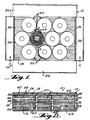
- the shipping package 10 comprises in general an exterior carton, generally indicated at 12, which defines an interior space.
- a top panel 14, a bottom panel 16 and usually at least one divider panel 18 are mounted within the interior space of the carton 12 so as to divide the same into a plurality of tiered spaces, each of which has a plurality of coiled fastener packages, generally indicated at 20, stably supported therein.
- the carton 12 may be of any conventional construction and, as shown, is formed of corrugated board which is cut, scored and folded to provide a bottom 22 of generally rectangular configuration in plan. Extending upwardly from the periphery of the bottom 22 are four interconnected sides 24 having flaps hinged to their upper edges capable of being closed to form a top closure 26.
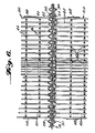
- all of the panels within the interior space of the carton 12, including the top panel 14, the bottom panel 16 and each divider panel 18, are of substantially identical construction, and consequently, a description of one will suffice to give an understanding of all.
- each panel includes an upwardly facing corrugated sheet 28, a downwardly facing corrugated sheet 30 and a pair of interior flat sheets 32 and 34 which are fixed together, as by gluing or the like, in face to face relation with respect to each other.
- Flat sheet 32 has its upper face fixed, as by gluing or the like, to the opposite face of the upwardly facing corrugated sheet 28.
- Flat sheet 34 has its lower face fixed, as by gluing or the like, to the opposite face of the downwardly facing corrugated sheet 30.
- the corrugated sheets 28 and 30 are so oriented with respect to one another that the corrugations of both sheets are disposed in parallel relation to one another.
- This parr-llel corrugation relationship is preferred because it is easier to fabricate and assemble the panel in this configuration. That is, fabrication and assembly proceeds with all four sheets in a continuous condition advancing longitudinally, and while so advancing, each corrugated sheet is first glued to its associated flat sheet and then the opposite faces of the flat sheets are glued together. Thereafter the sandwich is cut up into short lengths.
- This arrangement does not provide rigidity to the panel except in a direction perpendicular to the common parallel extent of the corrugations. Stated differently, the panel construction is capable of flexure in a direction parallel to the corrugations.
- a score line 36 is formed within both corrugated sheets along opposite edges of the panel which are perpendicular to the parallel extent of the corrugations. As shown, each score line 36 is spaced slightly inwardly from the associated edge so as to define a marginal edge portion 38 which is bent transversely along the score line. The transversely disposed marginal edge portions 38 at each end of each panel give the panel a shallow channel shaped configuration which iends rigidity to the panel in a direction parallel with the corrugations thereof.
- each coiled fastener package 20 is formed in accordance with the teachings contained in the aforesaid patent application from an assembly which includes a multiplicity of fasteners 40 which, as shown, are nails having an elongated shank, formed with a point 42 on one end and an enlarged head 44 on the opposite end thereof.
- the assembly also includes an elongated carrier for supporting the nails 40 in a row formation with their shanks in parallel relation to one another and extending transversely to the direction of elongation of the carrier.
- the carrier is in the form of two parallel weldable wires 46 which are disposed across the shanks of the nails and welded thereto.
- Each coiled package 20 is formed from the assembly by wrapping the assembly into a coil formation taking care to change the lapped relationship of the heads after each volute has been wrapped so that the heads alternate in alternating volutes from overlapping relation to underlapping relation to overlapping relation, etc.
- the outer periphery of the coil formation is secured by wrapping a band 48 thereabout
- the band 48 may be a rubber band or a paper band formed of a strip with the ends glued together. While it is preferred to use a band, the securement may be effected by a clip which serves to connect the outermost fastener to an adjacent fastener in the next volute.
- the flaps constituting the top closure 26 of the carton 12 are moved into an open position, such as shown in Figure 1, and then the bottom panel 16 is placed within the interior space of the carton in abutting relation with the bottom 22 thereof.
- marginal end portions 38 engage the associated carton sides 24 and are bent transversely upwardly so as to maintain the panel in its shallow channel configuration providing rigidity against flexure of the panel in a direction parallel with the corrugations.
- a series of fastener packages 20 are mounted on the upwardly facing corrugated sheet 28 of the bottom panel 16.
- Figure 1 illustrates a typical number of packages and a typical arrangement.
- the divider panel 18 is mounted within the interior space of the open carton 12 in engagement with the upper surfaces of the coiled fastener packages 20.
- each of the panels is mounted within the interior space of the carton so that the marginal end portions 38 are bent transversely.
- the bottom panel 16 has its marginal edge portions 38 bent upwardly.
- the top panel 14 has its marginal edge portions 38 bent downwardly, and each divider panel 18 may have its marginal edge portions 38 bent either upwardly or downwardly.
- each tiered space is defined by an upwardly facing corrugated sheet 28 and the upper surface of each tiered space is defined by a downwardly facing corrugated sheet 30.
- each package 20 may be regarded as seating upwardly and held within a downwardly facing recess formed by the collapse of the corrugations, whereas the pointed end of each package is held in pierced relation by the associated upwardly facing corrugated sheet 28.
- the combination of these two modes of retaining the ends of the fastener packages against movement effectively prevents their damage in shipment.
- the panels are preferably formed of conventional kraft paper which is relatively low cost. biodegradable and capable of non-toxic burning. It thus will be seen that the objects of this invention have been fully and effectively accomplished. It will be realized, however, that the foregoing preferred specific embodiment has been shown and described for the purpose of illustrating the functional and structural principles of this invention and is subject to change without departure from such principles. Therefore, this invention includes all modi- .fications encompassed within the spirit and scope of the following claims.
Landscapes
- Engineering & Computer Science (AREA)
- Mechanical Engineering (AREA)
- Packages (AREA)
- Packaging Of Annular Or Rod-Shaped Articles, Wearing Apparel, Cassettes, Or The Like (AREA)
- Cartons (AREA)
Priority Applications (1)
| Application Number | Priority Date | Filing Date | Title |
|---|---|---|---|
| AT85307053T ATE41907T1 (de) | 1984-10-16 | 1985-10-02 | Transportbehaelter fuer verpackungen von aufgerollten verbindungselementen. |
Applications Claiming Priority (2)
| Application Number | Priority Date | Filing Date | Title |
|---|---|---|---|
| US66147584A | 1984-10-16 | 1984-10-16 | |
| US661475 | 1984-10-16 |
Publications (3)
| Publication Number | Publication Date |
|---|---|
| EP0180341A2 true EP0180341A2 (de) | 1986-05-07 |
| EP0180341A3 EP0180341A3 (en) | 1987-04-01 |
| EP0180341B1 EP0180341B1 (de) | 1989-04-05 |
Family
ID=24653757
Family Applications (1)
| Application Number | Title | Priority Date | Filing Date |
|---|---|---|---|
| EP85307053A Expired EP0180341B1 (de) | 1984-10-16 | 1985-10-02 | Transportbehälter für Verpackungen von aufgerollten Verbindungselementen |
Country Status (6)
| Country | Link |
|---|---|
| EP (1) | EP0180341B1 (de) |
| JP (1) | JPS61164976A (de) |
| AT (1) | ATE41907T1 (de) |
| AU (1) | AU583058B2 (de) |
| CA (1) | CA1262115A (de) |
| DE (1) | DE3569224D1 (de) |
Cited By (2)
| Publication number | Priority date | Publication date | Assignee | Title |
|---|---|---|---|---|
| EP0935969A3 (de) * | 1998-02-10 | 1999-12-29 | Becton, Dickinson and Company | Verpackungen von einen endlosen weichen Streifen für medizinische Spritzen |
| CN114603932A (zh) * | 2022-03-18 | 2022-06-10 | 大连胜光科技发展有限公司 | 一种卷式金属包装用链板式结构及制作方法 |
Family Cites Families (8)
| Publication number | Priority date | Publication date | Assignee | Title |
|---|---|---|---|---|
| BE410433A (de) * | ||||
| US2185920A (en) * | 1936-07-17 | 1940-01-02 | American Viscose Corp | Shipping container |
| FR985316A (fr) * | 1949-04-29 | 1951-07-17 | Cartonneries Mecaniques Du Nor | Perfectionnements aux emballages pour articles de verrerie ou analogues |
| FR1020155A (fr) * | 1950-06-14 | 1953-02-03 | Dispositif de calage pour casiers et caisses d'emballage à cloisonnements | |
| US3598233A (en) * | 1970-02-19 | 1971-08-10 | Robert Jasinover | Container |
| US3990576A (en) * | 1975-01-30 | 1976-11-09 | Anthony's Manufacturing Company, Inc. | Transparent container for glass panels |
| US4194678A (en) * | 1978-07-10 | 1980-03-25 | American Hospital Supply Corporation | Shipping container and blank for forming same |
| DE3307418A1 (de) * | 1983-03-03 | 1984-09-06 | Häfele KG, 7270 Nagold | Aus unterteil und stuelpdeckel bestehende versandpackung fuer blisterpackungen und dgl. |
-
1985
- 1985-10-02 DE DE8585307053T patent/DE3569224D1/de not_active Expired
- 1985-10-02 EP EP85307053A patent/EP0180341B1/de not_active Expired
- 1985-10-02 AT AT85307053T patent/ATE41907T1/de not_active IP Right Cessation
- 1985-10-03 AU AU48240/85A patent/AU583058B2/en not_active Ceased
- 1985-10-15 CA CA000492986A patent/CA1262115A/en not_active Expired
- 1985-10-15 JP JP60227971A patent/JPS61164976A/ja active Pending
Cited By (2)
| Publication number | Priority date | Publication date | Assignee | Title |
|---|---|---|---|---|
| EP0935969A3 (de) * | 1998-02-10 | 1999-12-29 | Becton, Dickinson and Company | Verpackungen von einen endlosen weichen Streifen für medizinische Spritzen |
| CN114603932A (zh) * | 2022-03-18 | 2022-06-10 | 大连胜光科技发展有限公司 | 一种卷式金属包装用链板式结构及制作方法 |
Also Published As
| Publication number | Publication date |
|---|---|
| JPS61164976A (ja) | 1986-07-25 |
| EP0180341B1 (de) | 1989-04-05 |
| DE3569224D1 (en) | 1989-05-11 |
| AU4824085A (en) | 1986-04-24 |
| CA1262115A (en) | 1989-10-03 |
| ATE41907T1 (de) | 1989-04-15 |
| AU583058B2 (en) | 1989-04-20 |
| EP0180341A3 (en) | 1987-04-01 |
Similar Documents
| Publication | Publication Date | Title |
|---|---|---|
| US4712676A (en) | Shipping package containing coiled fastener packages | |
| US4623072A (en) | Corrugated container with foldable flaps | |
| US4770339A (en) | Ventilated, stackable grape box | |
| US3434648A (en) | Reinforced container structure | |
| US3373921A (en) | Shipping container | |
| US2885073A (en) | Packaging of self-sealing shingles | |
| EP0279488B1 (de) | Verpackungsvorrichtung | |
| US4860944A (en) | Carton and blank therefor | |
| US4567996A (en) | Two-piece container | |
| US5370303A (en) | One piece grape box | |
| US4353495A (en) | Asparagus carton | |
| US4674633A (en) | Container-retaining box | |
| US4042164A (en) | Container end structure | |
| US3980221A (en) | Package cushioning structure | |
| CA1053191A (en) | Carrier with drop down partition | |
| US4169417A (en) | Support foot device for load carriers | |
| US5769216A (en) | Holder for compact disc and the like | |
| US4003515A (en) | Handle container | |
| US2301927A (en) | Merchandising package | |
| US2776082A (en) | Egg carton | |
| US4211358A (en) | Lug box having cored-out plastic end walls | |
| EP0180341B1 (de) | Transportbehälter für Verpackungen von aufgerollten Verbindungselementen | |
| US4347969A (en) | Tray | |
| US2514295A (en) | Cushioned packing box | |
| US3126144A (en) | figures |
Legal Events
| Date | Code | Title | Description |
|---|---|---|---|
| PUAI | Public reference made under article 153(3) epc to a published international application that has entered the european phase |
Free format text: ORIGINAL CODE: 0009012 |
|
| AK | Designated contracting states |
Kind code of ref document: A2 Designated state(s): AT BE CH DE FR GB IT LI LU NL SE |
|
| PUAL | Search report despatched |
Free format text: ORIGINAL CODE: 0009013 |
|
| AK | Designated contracting states |
Kind code of ref document: A3 Designated state(s): AT BE CH DE FR GB IT LI LU NL SE |
|
| 17P | Request for examination filed |
Effective date: 19870225 |
|
| RAP1 | Party data changed (applicant data changed or rights of an application transferred) |
Owner name: STANLEY-BOSTITCH, INC. |
|
| 17Q | First examination report despatched |
Effective date: 19880208 |
|
| ITF | It: translation for a ep patent filed | ||
| GRAA | (expected) grant |
Free format text: ORIGINAL CODE: 0009210 |
|
| AK | Designated contracting states |
Kind code of ref document: B1 Designated state(s): AT BE CH DE FR GB IT LI LU NL SE |
|
| REF | Corresponds to: |
Ref document number: 41907 Country of ref document: AT Date of ref document: 19890415 Kind code of ref document: T |
|
| REF | Corresponds to: |
Ref document number: 3569224 Country of ref document: DE Date of ref document: 19890511 |
|
| ET | Fr: translation filed | ||
| PG25 | Lapsed in a contracting state [announced via postgrant information from national office to epo] |
Ref country code: LU Free format text: LAPSE BECAUSE OF NON-PAYMENT OF DUE FEES Effective date: 19891031 |
|
| PLBE | No opposition filed within time limit |
Free format text: ORIGINAL CODE: 0009261 |
|
| STAA | Information on the status of an ep patent application or granted ep patent |
Free format text: STATUS: NO OPPOSITION FILED WITHIN TIME LIMIT |
|
| 26N | No opposition filed | ||
| PGFP | Annual fee paid to national office [announced via postgrant information from national office to epo] |
Ref country code: GB Payment date: 19900907 Year of fee payment: 6 Ref country code: FR Payment date: 19900907 Year of fee payment: 6 |
|
| PGFP | Annual fee paid to national office [announced via postgrant information from national office to epo] |
Ref country code: SE Payment date: 19900920 Year of fee payment: 6 |
|
| PGFP | Annual fee paid to national office [announced via postgrant information from national office to epo] |
Ref country code: AT Payment date: 19901002 Year of fee payment: 6 |
|
| ITTA | It: last paid annual fee | ||
| PGFP | Annual fee paid to national office [announced via postgrant information from national office to epo] |
Ref country code: NL Payment date: 19901031 Year of fee payment: 6 |
|
| PGFP | Annual fee paid to national office [announced via postgrant information from national office to epo] |
Ref country code: BE Payment date: 19901211 Year of fee payment: 6 |
|
| PGFP | Annual fee paid to national office [announced via postgrant information from national office to epo] |
Ref country code: DE Payment date: 19901227 Year of fee payment: 6 |
|
| PGFP | Annual fee paid to national office [announced via postgrant information from national office to epo] |
Ref country code: CH Payment date: 19910110 Year of fee payment: 6 |
|
| PG25 | Lapsed in a contracting state [announced via postgrant information from national office to epo] |
Ref country code: GB Effective date: 19911002 Ref country code: AT Effective date: 19911002 |
|
| PG25 | Lapsed in a contracting state [announced via postgrant information from national office to epo] |
Ref country code: SE Effective date: 19911003 |
|
| PG25 | Lapsed in a contracting state [announced via postgrant information from national office to epo] |
Ref country code: LI Effective date: 19911031 Ref country code: CH Effective date: 19911031 Ref country code: BE Effective date: 19911031 |
|
| BERE | Be: lapsed |
Owner name: STANLEY-BOSTITCH INC. Effective date: 19911031 |
|
| PG25 | Lapsed in a contracting state [announced via postgrant information from national office to epo] |
Ref country code: NL Effective date: 19920501 |
|
| GBPC | Gb: european patent ceased through non-payment of renewal fee | ||
| NLV4 | Nl: lapsed or anulled due to non-payment of the annual fee | ||
| PG25 | Lapsed in a contracting state [announced via postgrant information from national office to epo] |
Ref country code: FR Effective date: 19920630 |
|
| REG | Reference to a national code |
Ref country code: CH Ref legal event code: PL |
|
| PG25 | Lapsed in a contracting state [announced via postgrant information from national office to epo] |
Ref country code: DE Effective date: 19920701 |
|
| REG | Reference to a national code |
Ref country code: FR Ref legal event code: ST |
|
| EUG | Se: european patent has lapsed |
Ref document number: 85307053.0 Effective date: 19920510 |