EP0180248A2 - Valve arrangement - Google Patents
Valve arrangement Download PDFInfo
- Publication number
- EP0180248A2 EP0180248A2 EP85113983A EP85113983A EP0180248A2 EP 0180248 A2 EP0180248 A2 EP 0180248A2 EP 85113983 A EP85113983 A EP 85113983A EP 85113983 A EP85113983 A EP 85113983A EP 0180248 A2 EP0180248 A2 EP 0180248A2
- Authority
- EP
- European Patent Office
- Prior art keywords
- valve
- pressure
- line
- control element
- fuel
- Prior art date
- Legal status (The legal status is an assumption and is not a legal conclusion. Google has not performed a legal analysis and makes no representation as to the accuracy of the status listed.)
- Granted
Links
Images

Classifications
-
- F—MECHANICAL ENGINEERING; LIGHTING; HEATING; WEAPONS; BLASTING
- F02—COMBUSTION ENGINES; HOT-GAS OR COMBUSTION-PRODUCT ENGINE PLANTS
- F02C—GAS-TURBINE PLANTS; AIR INTAKES FOR JET-PROPULSION PLANTS; CONTROLLING FUEL SUPPLY IN AIR-BREATHING JET-PROPULSION PLANTS
- F02C9/00—Controlling gas-turbine plants; Controlling fuel supply in air- breathing jet-propulsion plants
- F02C9/26—Control of fuel supply
- F02C9/263—Control of fuel supply by means of fuel metering valves
-
- F—MECHANICAL ENGINEERING; LIGHTING; HEATING; WEAPONS; BLASTING
- F02—COMBUSTION ENGINES; HOT-GAS OR COMBUSTION-PRODUCT ENGINE PLANTS
- F02C—GAS-TURBINE PLANTS; AIR INTAKES FOR JET-PROPULSION PLANTS; CONTROLLING FUEL SUPPLY IN AIR-BREATHING JET-PROPULSION PLANTS
- F02C9/00—Controlling gas-turbine plants; Controlling fuel supply in air- breathing jet-propulsion plants
- F02C9/26—Control of fuel supply
- F02C9/28—Regulating systems responsive to plant or ambient parameters, e.g. temperature, pressure, rotor speed
-
- Y—GENERAL TAGGING OF NEW TECHNOLOGICAL DEVELOPMENTS; GENERAL TAGGING OF CROSS-SECTIONAL TECHNOLOGIES SPANNING OVER SEVERAL SECTIONS OF THE IPC; TECHNICAL SUBJECTS COVERED BY FORMER USPC CROSS-REFERENCE ART COLLECTIONS [XRACs] AND DIGESTS
- Y02—TECHNOLOGIES OR APPLICATIONS FOR MITIGATION OR ADAPTATION AGAINST CLIMATE CHANGE
- Y02T—CLIMATE CHANGE MITIGATION TECHNOLOGIES RELATED TO TRANSPORTATION
- Y02T50/00—Aeronautics or air transport
- Y02T50/60—Efficient propulsion technologies, e.g. for aircraft
-
- Y—GENERAL TAGGING OF NEW TECHNOLOGICAL DEVELOPMENTS; GENERAL TAGGING OF CROSS-SECTIONAL TECHNOLOGIES SPANNING OVER SEVERAL SECTIONS OF THE IPC; TECHNICAL SUBJECTS COVERED BY FORMER USPC CROSS-REFERENCE ART COLLECTIONS [XRACs] AND DIGESTS
- Y10—TECHNICAL SUBJECTS COVERED BY FORMER USPC
- Y10T—TECHNICAL SUBJECTS COVERED BY FORMER US CLASSIFICATION
- Y10T137/00—Fluid handling
- Y10T137/7722—Line condition change responsive valves
- Y10T137/7737—Thermal responsive
-
- Y—GENERAL TAGGING OF NEW TECHNOLOGICAL DEVELOPMENTS; GENERAL TAGGING OF CROSS-SECTIONAL TECHNOLOGIES SPANNING OVER SEVERAL SECTIONS OF THE IPC; TECHNICAL SUBJECTS COVERED BY FORMER USPC CROSS-REFERENCE ART COLLECTIONS [XRACs] AND DIGESTS
- Y10—TECHNICAL SUBJECTS COVERED BY FORMER USPC
- Y10T—TECHNICAL SUBJECTS COVERED BY FORMER US CLASSIFICATION
- Y10T137/00—Fluid handling
- Y10T137/7722—Line condition change responsive valves
- Y10T137/7758—Pilot or servo controlled
- Y10T137/7762—Fluid pressure type
- Y10T137/7769—Single acting fluid servo
- Y10T137/777—Spring biased
Definitions
- a valve arrangement in a gas turbine fuel control system includes a main valve responsive to a servo pressure and a separate servo pressure regulating valve which is responsive to conditions which the main valve is required to control.
- the main valve acts to spill fuel from upstream of a variable metering device
- the servo pressure regulating valve is responsive to the pressure upstream and downstream of the metering device, whereby fuel is spilled by the main valve in such a way as to maintain a pressure difference across the metering device substantially constant.
- a valve arrangement for a gas turbine engine fuel control system comprises a housing having an inlet and an outlet, a control element axially movable in response to a servo pressure in a chamber in said housing to control flow between said inlet and said outlet, and a regulating valve responsive to the pressure at said inlet and to a further downstream pressure, for deriving said servo pressure from an external source, said regulating valve being provided by a piston slidable in said chamber relative to said control element, a part of said piston co-operating with said control element to define said regulating valve.
- a gas turbine engine 10 is supplied with fuel from a positive displacement pump 11, fuel flow being regulated by a variable metering device 12 which is under control of a high integrity digital computer 13 which is responsive to desired and sensed operating conditions of the engine 10.
- the metering device 12 is shown in more detail in Figure 3, and fuel flow therefrom passes to the engine 10 by way of an arrangement 14 shown in more detail in Figure 4.
- Fuel flow to the engine 10 may be limited by a combined pressure relief and spill valve arrangement 15 which is shown in more detail in Figure 2, and to which fuel is delivered by the pump 11 through a line 16.
- a filter connection 17 to the line 16 provides high pressure filtered fuel to a delivery line 18.
- the arrangement 15 includes a relief valve 20 having a control element 21 which has a lesser area responsive to the pressure in line 16 and a larger area responsive to a servo pressure in a chamber 22.
- the element 21 is also biassed against the pressure in line 16 by a spring 23.
- the valve 20 is operable to spill fuel from the line 16 to a low pressure return line 24 which communicates with the upstream side of the pump 11.
- the pressure in chamber 22 is derived from that in line 18 in a manner to be described and is applied through a line 68.
- the pressure in chamber 22 can also be regulated through a line 25 and a port 26, the port being shut off by the control element 21 when the valve 20 is half open.
- the chamber 22 can be connected to the low pressure return line 24 by means of an electromagnetic valve 27 which is opened by an electrical signal on a line 28 in response to a requirement to shut down fuel flow to the engine 10. Energisation of the valve 27 allows the valve 20 to become fully open and substantially all of the fuel in line 16 to be spilled to the return line 24.
- the consequent reduction of pressure in line 16 is used, in a manner to be described, to maintain a low pressure in the chamber 22, and hence a low pressure in line 16, even after the valve 27 has subsequently been shut.
- the metering device 12 shown in Figure 3 includes a metering valve 30 which receives fuel on the line 16 from the pump 11.
- the valve 30 includes a control element 31 which is responsive to the pressure in a chamber 32.
- a valve 33 and a flow restrictor 34 are arranged in series between a chamber 35 and the high pressure line 18.
- the chamber 35 communicates by way of a passage 36 with the low pressure return line 24.
- the pressure in chamber 32 is that intermediate the valve 33 and restrictor 34.
- the valve 33 is pivotally movable by a dual-coil torque motor 37, each separate coil of the motor 37 being effective to operate the valve 33. Current is supplied to respective coils of the motor 37 from drive circuits (not shown) associated with the digital computer 13.
- the control element 31 regulates fuel flow from the line 16 to a line 38 and the operating position of the element 31 is detected by a synchro-resolver 39 from which the computer 13 derives position signals.
- a feedback spring 40 coacts with the control element 31 and with the valve 33 so that movement of the element 31 alters the bias on the valve 33 in such a way as to vary the pressure in chamber 32 to oppose the aforesaid movement of the control element 31.
- An adjustable orifice 41 allows a small quantity of fuel to flow from the high pressure line 18 to the line 38, providing an additional fuel flow to the engine, this additional fuel flow having a maximum effect during engine starting, when metered fuel flow would otherwise be low.
- the metering device 12 also includes a valve arrangement 50 for spilling fuel from the line 16 back to the low pressure return line 24.
- the spill valve 50 has a control element 51 which is slidable in a bore 52 to control flow between the lines 16, 24.
- the control element 51 is responsive to a servo pressure in a chamber 53 which is defined between a housing 54 and one end of the control element 51.
- a piston 55 is slidable within the control element 51 and includes a stem 56 which extends through the end of the control element 51 and defines, in conjunction with that end, a valve 57 for regulating servo pressure in the chamber 53.
- the valve 57 is in series with a flow restrictor 58 between the line 18 and a passage 59 which communicates with the line 38 downstream of the metering valve 30.
- the piston 55 is thus responsive to a difference between the pressures upstream and downstream of the metering valve 30 and is biassed against movement in response to this pressure difference by a spring 60 which is supported by means of a collar 61 on a stack 62 of bi-metal discs which are responsive to fuel temperature.
- the bias applied by the spring 60, for a given position of the piston 55, is thus adjusted in accordance with fuel temperature.
- a further spring 63 acts to shut the valve 50 on the absence of a pressure in the line 16.
- the arrangement 14 includes a pressure raising valve 70 to which fuel can flow through the line 38 and has a control element 71 biassed by a spring 72 towards a shut position, the element 71 being movable against the spring 72 by the pressure in line 38, to allow fuel flow to the engine 10 through a delivery line 73.
- a function of the valve 70 is to prevent fuel flow to the engine 10 until the fuel pressure within the system has reached a predetermined level which is sufficient to provide the necessary operating servo pressures.
- the control element 71 includes an annular groove 69 which, when the valve 70 is shut, interconnects ports 74 and 75.
- the port 74 communicates through a line 68 with the servo pressure chamber 22 of the spill valve 20 ( Figure 2).
- the arrangement 14 also includes a servo pressure control device 76 which has a valve 77 which is biassed shut by an adjustable spring 78 and which can be moved against this spring by a torque motor 79 when the latter is rotated clockwise, as viewed in the drawing.
- the valve 77 is operable by the torque motor 79 to connect the chamber 22 ( Figure 2) to the low pressure return line 24, by way of the port 26 and line 25.
- the device 76 includes a further valve 80 which is also controlled by torque motor 79, the valve 80 being open in the de-energised condition of the motor 79.
- the valve 80 connects the low pressure return line 24 to the port 75 of valve 70.
- the port 75 also communicates with the line 18 through flow restrictor 81.
- the line 68 communicates with the line 18 through a restrictor 82.
- the torque motor 79 is operated by signals from a computer 83 ( Figure 1) which is responsive to the speeds NL and NI of low and intermediate pressure shafts respectively of the engine 10.
- a computer 83 Figure 1
- An apparatus for controlling a valve in response to overspeeding by either of two shafts of a gas turbine engine is described in UK patent application 8220913, and such an apparatus may be used to energise the torque motor 79 in the present invention. If either speed exceeds a predetermined level the computer 83 energises the torque motor 79 clockwise to open the valve 77 and thereby to reduce the servo pressure in chamber 22 by way of the line 25. The relief valve 20 thus opens to reduce fuel pressure in the line 16, and hence flow to the engine 10.
- valve 20 The amount by which the valve 20 can open is limited by the position of the port 26, which shuts when the valve 20 is approximately half open.
- the control element 21 of the valve 20 adopts an equilibrium position in which flow through the restrictor 82, line 68, port 26, line 25 and valve 77 results in an intermediate pressure in chamber 22, this intermediate pressure acting on the larger area of the element 21 to balance the pump delivery pressure acting on the smaller area of that element.
- the torque motor 79 allows the valve 77 to be shut by the spring 78, the servo pressure in line 25 rises towards that in line 18, and the valve 20 shuts.
- valve 77 is normally shut and, as described above, if the valve 27 ( Figure 2) is energised the servo pressure in chamber 22 falls to a low value and the valve 20 can become fully open to spill substantially all of the fuel from line 16. the resulting drop in system pressure allows the valve 70 ( Figure 4) to shut under the influence of the spring 72, thereby preventing fuel from reaching the engine 10 through the line 73. In this condition of the valve 70 the ports 74, 75 are interconnected by the groove 69 so that the servo pressure in the chamber 22 of the valve 20 is connected to the low pressure return line 24 through the line 68, the ports 74, 75 and the valve 80.
- an indicator device 84 ( Figure 1) is energised through a microswitch 35, and a plate valve 86 is opened to connect a drain Line 87 from the engine fuel manifold to a dump connection 88.
- the microswitch 85 also causes the electromagnetic valve 27 to be de-energised, and therefore shut. Pressure in chamber 22 is nevertheless maintained low by the interconnection between the ports 74, 75 as aforesaid.
- the rising pressure in line 68 shuts the valve 20 and further raises the pressure in lines 16, 18.
- the pressure in line 18 is applied through restrictors 81, 82 and the port 75 to open a start valve 90 against a spring 92.
- the valve 70 is shut fuel can nevertheless pass from the line 38 through a passage 95 to a start supply line 91.
- the valve 70 opens, supplying fuel to the main burners of the engine 10 through the line 73.
- the torque motor 79 is de-energised, opening the valve 80 and removing pressure from the start valve 90 which is then shut by its spring 92.
- the valve 90 is maintained shut by the pressure in line 38, applied through a line 95.
- An orifice 96 ( Figure 1) interconnects the lines 73 and 91 and permits fuel to flow continuously to the starter jets of the engine 10, through the line 91, and thereby prevents charred fuel residues from accumulating in the starter jets.
- the fuel pressure in line 16 is applied to the valve 77 through the line 18, restrictor 82, line 68 and line 25. If this pressure exceeds a value which is set by the spring 78, and which is a predetermined multiple, for example 1.1, of normal system pressure in line 16, the valve 77 lifts and thereby prevent the pressure in the chamber 22 of valve 20 ( Figure 1) from rising in response to any further increase in the system pressure. Any such further increases will cause the valve 20 to open and spill fuel from the outlet of the pump.
- the valves 77 and 20 thereby co-operate to provide a system pressure relief device.
Abstract
Description
- It is known, for example from GB-A-2088962 to provide that a valve arrangement in a gas turbine fuel control system includes a main valve responsive to a servo pressure and a separate servo pressure regulating valve which is responsive to conditions which the main valve is required to control. In the foregoing reference the main valve acts to spill fuel from upstream of a variable metering device, and the servo pressure regulating valve is responsive to the pressure upstream and downstream of the metering device, whereby fuel is spilled by the main valve in such a way as to maintain a pressure difference across the metering device substantially constant.
- In a fuel control system for an aircraft engine it is desirable to reduce size and weight as much as possible. It is an object of the invention to provide a valve arrangement in which the main and servo pressure regulating valve are combined in a single assembly so that one or more components of one of the valves can also act as a component of the other valve.
- It will be apparent that these considerations apply to valve arrangements other than those for controlling a metering pressure difference.
- According to the invention a valve arrangement for a gas turbine engine fuel control system comprises a housing having an inlet and an outlet, a control element axially movable in response to a servo pressure in a chamber in said housing to control flow between said inlet and said outlet, and a regulating valve responsive to the pressure at said inlet and to a further downstream pressure, for deriving said servo pressure from an external source, said regulating valve being provided by a piston slidable in said chamber relative to said control element, a part of said piston co-operating with said control element to define said regulating valve.
- An embodiment of the invention will now be described by way of example only, and with reference to the accompanying drawings, in which:-
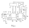
- Figure 1 is a block diagram of a
fuel control 15 system for a gas turbine engine; - Figure 2 is a diagram of a flow limiting spill valve arrangement, forming part of Figure 1;
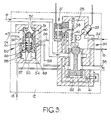
- Figure 3 is a diagram of a variable metering device forming part of Figure 1, and incorporating a valve arrangement according to the invention, and
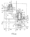
- Figure 4 is a diagram of a pressure raising and servo pressure control arrangement forming part of Figure 1.
- As shown in Figure 1, a
gas turbine engine 10 is supplied with fuel from apositive displacement pump 11, fuel flow being regulated by avariable metering device 12 which is under control of a high integritydigital computer 13 which is responsive to desired and sensed operating conditions of theengine 10. Themetering device 12 is shown in more detail in Figure 3, and fuel flow therefrom passes to theengine 10 by way of anarrangement 14 shown in more detail in Figure 4. Fuel flow to theengine 10 may be limited by a combined pressure relief andspill valve arrangement 15 which is shown in more detail in Figure 2, and to which fuel is delivered by thepump 11 through aline 16. Afilter connection 17 to theline 16 provides high pressure filtered fuel to adelivery line 18. - As shown in Figure 2, the
arrangement 15 includes arelief valve 20 having a control element 21 which has a lesser area responsive to the pressure inline 16 and a larger area responsive to a servo pressure in achamber 22. The element 21 is also biassed against the pressure inline 16 by aspring 23. Thevalve 20 is operable to spill fuel from theline 16 to a lowpressure return line 24 which communicates with the upstream side of thepump 11. The pressure inchamber 22 is derived from that inline 18 in a manner to be described and is applied through aline 68. The pressure inchamber 22 can also be regulated through aline 25 and aport 26, the port being shut off by the control element 21 when thevalve 20 is half open. Reduction of pressure in theline 16 in response to a reduction of the servo pressure inline 25 is thereby limited. Thechamber 22 can be connected to the lowpressure return line 24 by means of anelectromagnetic valve 27 which is opened by an electrical signal on aline 28 in response to a requirement to shut down fuel flow to theengine 10. Energisation of thevalve 27 allows thevalve 20 to become fully open and substantially all of the fuel inline 16 to be spilled to thereturn line 24. The consequent reduction of pressure inline 16 is used, in a manner to be described, to maintain a low pressure in thechamber 22, and hence a low pressure inline 16, even after thevalve 27 has subsequently been shut. - The
metering device 12 shown in Figure 3 includes ametering valve 30 which receives fuel on theline 16 from thepump 11. Thevalve 30 includes acontrol element 31 which is responsive to the pressure in achamber 32. Avalve 33 and aflow restrictor 34 are arranged in series between achamber 35 and thehigh pressure line 18. Thechamber 35 communicates by way of apassage 36 with the lowpressure return line 24. The pressure inchamber 32 is that intermediate thevalve 33 andrestrictor 34. Thevalve 33 is pivotally movable by a dual-coil torque motor 37, each separate coil of themotor 37 being effective to operate thevalve 33. Current is supplied to respective coils of themotor 37 from drive circuits (not shown) associated with thedigital computer 13. Thecontrol element 31 regulates fuel flow from theline 16 to aline 38 and the operating position of theelement 31 is detected by a synchro-resolver 39 from which thecomputer 13 derives position signals. Afeedback spring 40 coacts with thecontrol element 31 and with thevalve 33 so that movement of theelement 31 alters the bias on thevalve 33 in such a way as to vary the pressure inchamber 32 to oppose the aforesaid movement of thecontrol element 31. Anadjustable orifice 41 allows a small quantity of fuel to flow from thehigh pressure line 18 to theline 38, providing an additional fuel flow to the engine, this additional fuel flow having a maximum effect during engine starting, when metered fuel flow would otherwise be low. - The
metering device 12 also includes avalve arrangement 50 for spilling fuel from theline 16 back to the lowpressure return line 24. Thespill valve 50 has acontrol element 51 which is slidable in abore 52 to control flow between thelines control element 51 is responsive to a servo pressure in achamber 53 which is defined between ahousing 54 and one end of thecontrol element 51. Apiston 55 is slidable within thecontrol element 51 and includes a stem 56 which extends through the end of thecontrol element 51 and defines, in conjunction with that end, avalve 57 for regulating servo pressure in thechamber 53. Thevalve 57 is in series with aflow restrictor 58 between theline 18 and apassage 59 which communicates with theline 38 downstream of themetering valve 30. Thepiston 55 is thus responsive to a difference between the pressures upstream and downstream of themetering valve 30 and is biassed against movement in response to this pressure difference by aspring 60 which is supported by means of acollar 61 on a stack 62 of bi-metal discs which are responsive to fuel temperature. The bias applied by thespring 60, for a given position of thepiston 55, is thus adjusted in accordance with fuel temperature. Afurther spring 63 acts to shut thevalve 50 on the absence of a pressure in theline 16. - An increase in the pressure difference across the
metering valve 30 causes thepiston 55 to move downwardly, opening thevalve 57 and reducing the servo pressure in thechamber 53. Thecontrol element 51 then moves downwardly to increase spill flow until the aforesaid pressure difference returns to its original value. - As shown in Figure 4, the
arrangement 14 includes apressure raising valve 70 to which fuel can flow through theline 38 and has acontrol element 71 biassed by aspring 72 towards a shut position, theelement 71 being movable against thespring 72 by the pressure inline 38, to allow fuel flow to theengine 10 through adelivery line 73. A function of thevalve 70 is to prevent fuel flow to theengine 10 until the fuel pressure within the system has reached a predetermined level which is sufficient to provide the necessary operating servo pressures. Thecontrol element 71 includes an annular groove 69 which, when thevalve 70 is shut, interconnectsports port 74 communicates through aline 68 with theservo pressure chamber 22 of the spill valve 20 (Figure 2). Thearrangement 14 also includes a servopressure control device 76 which has avalve 77 which is biassed shut by anadjustable spring 78 and which can be moved against this spring by atorque motor 79 when the latter is rotated clockwise, as viewed in the drawing. Thevalve 77 is operable by thetorque motor 79 to connect the chamber 22 (Figure 2) to the lowpressure return line 24, by way of theport 26 andline 25. - The
device 76 includes afurther valve 80 which is also controlled bytorque motor 79, thevalve 80 being open in the de-energised condition of themotor 79. Thevalve 80 connects the lowpressure return line 24 to theport 75 ofvalve 70. Theport 75 also communicates with theline 18 throughflow restrictor 81. Theline 68 communicates with theline 18 through arestrictor 82. With thevalve 77 andport 75 shut the pump delivery pressure inline 18 is thus applied to the larger area of the control element 21 (Figure 2) to urge the latter shut against the pressure inline 16. - The
torque motor 79 is operated by signals from a computer 83 (Figure 1) which is responsive to the speeds NL and NI of low and intermediate pressure shafts respectively of theengine 10. An apparatus for controlling a valve in response to overspeeding by either of two shafts of a gas turbine engine is described in UK patent application 8220913, and such an apparatus may be used to energise thetorque motor 79 in the present invention. If either speed exceeds a predetermined level thecomputer 83 energises thetorque motor 79 clockwise to open thevalve 77 and thereby to reduce the servo pressure inchamber 22 by way of theline 25. Therelief valve 20 thus opens to reduce fuel pressure in theline 16, and hence flow to theengine 10. The amount by which thevalve 20 can open is limited by the position of theport 26, which shuts when thevalve 20 is approximately half open. With thevalve 77 open the control element 21 of thevalve 20 adopts an equilibrium position in which flow through therestrictor 82,line 68,port 26,line 25 andvalve 77 results in an intermediate pressure inchamber 22, this intermediate pressure acting on the larger area of the element 21 to balance the pump delivery pressure acting on the smaller area of that element. When the engine speed has fallen to an acceptable level thetorque motor 79 allows thevalve 77 to be shut by thespring 78, the servo pressure inline 25 rises towards that inline 18, and thevalve 20 shuts. - The
valve 77 is normally shut and, as described above, if the valve 27 (Figure 2) is energised the servo pressure inchamber 22 falls to a low value and thevalve 20 can become fully open to spill substantially all of the fuel fromline 16. the resulting drop in system pressure allows the valve 70 (Figure 4) to shut under the influence of thespring 72, thereby preventing fuel from reaching theengine 10 through theline 73. In this condition of thevalve 70 theports chamber 22 of thevalve 20 is connected to the lowpressure return line 24 through theline 68, theports valve 80. - When the
pressure raising valve 70 is shut an indicator device 84 (Figure 1) is energised through amicroswitch 35, and aplate valve 86 is opened to connect adrain Line 87 from the engine fuel manifold to adump connection 88. Themicroswitch 85 also causes theelectromagnetic valve 27 to be de-energised, and therefore shut. Pressure inchamber 22 is nevertheless maintained low by the interconnection between theports - When the engine is to be started the torque motor 79 (Figure 4) is energised anticlockwise, shutting the
valve 80. Thepressure raising valve 70 will at this stage be shut and theports valve 80 effectively over-rides the valve provided by theports line 68 can rise. - As the system pressure increases, the rising pressure in
line 68 shuts thevalve 20 and further raises the pressure inlines line 18 is applied throughrestrictors port 75 to open astart valve 90 against aspring 92. Though thevalve 70 is shut fuel can nevertheless pass from theline 38 through apassage 95 to a start supply line 91. When the system fuel pressure reaches a predetermined value thevalve 70 opens, supplying fuel to the main burners of theengine 10 through theline 73. - After the
engine 10 has been started thetorque motor 79 is de-energised, opening thevalve 80 and removing pressure from thestart valve 90 which is then shut by itsspring 92. Thevalve 90 is maintained shut by the pressure inline 38, applied through aline 95. An orifice 96 (Figure 1) interconnects thelines 73 and 91 and permits fuel to flow continuously to the starter jets of theengine 10, through the line 91, and thereby prevents charred fuel residues from accumulating in the starter jets. - The fuel pressure in
line 16 is applied to thevalve 77 through theline 18,restrictor 82,line 68 andline 25. If this pressure exceeds a value which is set by thespring 78, and which is a predetermined multiple, for example 1.1, of normal system pressure inline 16, thevalve 77 lifts and thereby prevent the pressure in thechamber 22 of valve 20 (Figure 1) from rising in response to any further increase in the system pressure. Any such further increases will cause thevalve 20 to open and spill fuel from the outlet of the pump. Thevalves
Claims (4)
Applications Claiming Priority (2)
| Application Number | Priority Date | Filing Date | Title |
|---|---|---|---|
| GB8230796 | 1982-10-28 | ||
| GB8230796 | 1982-10-28 |
Related Parent Applications (2)
| Application Number | Title | Priority Date | Filing Date |
|---|---|---|---|
| EP83306075A Division-Into EP0107940B1 (en) | 1982-10-28 | 1983-10-07 | Fuel control system for a gas turbine engine |
| EP83306075A Division EP0107940B1 (en) | 1982-10-28 | 1983-10-07 | Fuel control system for a gas turbine engine |
Publications (3)
| Publication Number | Publication Date |
|---|---|
| EP0180248A2 true EP0180248A2 (en) | 1986-05-07 |
| EP0180248A3 EP0180248A3 (en) | 1987-06-03 |
| EP0180248B1 EP0180248B1 (en) | 1989-12-13 |
Family
ID=10533888
Family Applications (2)
| Application Number | Title | Priority Date | Filing Date |
|---|---|---|---|
| EP83306075A Expired EP0107940B1 (en) | 1982-10-28 | 1983-10-07 | Fuel control system for a gas turbine engine |
| EP85113983A Expired EP0180248B1 (en) | 1982-10-28 | 1983-10-07 | Valve arrangement |
Family Applications Before (1)
| Application Number | Title | Priority Date | Filing Date |
|---|---|---|---|
| EP83306075A Expired EP0107940B1 (en) | 1982-10-28 | 1983-10-07 | Fuel control system for a gas turbine engine |
Country Status (4)
| Country | Link |
|---|---|
| US (1) | US4597407A (en) |
| EP (2) | EP0107940B1 (en) |
| JP (1) | JPS5993929A (en) |
| DE (2) | DE3380968D1 (en) |
Cited By (3)
| Publication number | Priority date | Publication date | Assignee | Title |
|---|---|---|---|---|
| WO1997027387A1 (en) * | 1996-01-25 | 1997-07-31 | Ametek Aerospace Products Inc. | Flowrate control system and method |
| US5795998A (en) * | 1995-12-12 | 1998-08-18 | Lucas Industries Public Limited Company | Flow sensor and fuel control system |
| FR2894622A1 (en) * | 1989-05-10 | 2007-06-15 | Lucas Ind Plc | Fuel control system i.e. gas turbine engine fuel control system, for reheat burner, has pressure drop regulating valve introducing fuel into fuel manifolds downstream of throttle valves when metering and throttle valves are shut |
Families Citing this family (15)
| Publication number | Priority date | Publication date | Assignee | Title |
|---|---|---|---|---|
| FR2594488B1 (en) * | 1986-02-19 | 1988-05-06 | Snecma | IMPROVEMENT TO HYDROMECHANICAL REGULATORS |
| GB8700652D0 (en) * | 1987-01-13 | 1987-02-18 | Lucas Ind Plc | Fluid powered actuator arrangement |
| FR2610040B1 (en) * | 1987-01-28 | 1991-02-08 | Snecma | MODULAR REGULATOR SUB-ASSEMBLY WITH INTEGRATED LOSS OF LOAD DETECTOR AND OVERSPEED LIMITER |
| FR2610041B1 (en) * | 1987-01-28 | 1989-03-17 | Snecma | REGULATING ASSEMBLY WITH IMPROVED FUEL DOSING, PARTICULARLY FOR TURBOMACHINES |
| GB8717169D0 (en) * | 1987-07-21 | 1987-08-26 | Ti Interlock Ltd | Pneumatic control system |
| GB9022387D0 (en) * | 1990-10-16 | 1990-11-28 | Lucas Ind Plc | Fuel control system for a gas turbine engine |
| GB9910074D0 (en) | 1999-04-30 | 1999-06-30 | Lucas Ind Plc | Fuel control system and valve therefor |
| GB0027288D0 (en) | 2000-11-08 | 2000-12-27 | Rolls Royce Plc | Overthrust protection system and method |
| GB0204054D0 (en) * | 2002-02-21 | 2002-04-10 | Lucas Industries Ltd | Fuel injection system for a combustion engine |
| US6962485B2 (en) * | 2003-04-14 | 2005-11-08 | Goodrich Pump And Engine Control Systems, Inc. | Constant bypass flow controller for a variable displacement pump |
| US8210156B2 (en) * | 2009-07-01 | 2012-07-03 | Ford Global Technologies, Llc | Fuel system with electrically-controllable mechanical pressure regulator |
| US8959920B2 (en) * | 2012-04-13 | 2015-02-24 | Eaton Corporation | Aircraft engine fuel pump bearing flow and associated system and method |
| CN105673209B (en) * | 2016-01-14 | 2017-08-22 | 中国航空动力机械研究所 | Fuel dispenser and aero-engine for aircraft engine fuel oil system |
| CN111120115B (en) * | 2019-12-31 | 2021-07-27 | 中国民用航空总局第二研究所 | Engine fire resistance test oil way precision automatic control system |
| US11808218B1 (en) | 2022-04-27 | 2023-11-07 | Hamilton Sundstrand Corporation | Rapid fuel shutdown system with latching |
Citations (3)
| Publication number | Priority date | Publication date | Assignee | Title |
|---|---|---|---|---|
| US2827075A (en) * | 1944-10-30 | 1958-03-18 | Mercier Jean | Servo pressure regulator valve |
| GB1237680A (en) * | 1968-12-20 | 1971-06-30 | Bendix Corp | Flow metering apparatus, particularly for combustion engine fuel control |
| GB2088962A (en) * | 1980-12-04 | 1982-06-16 | Lucas Industries Ltd | Fuel Control System for a Gas Turbine Engine |
Family Cites Families (4)
| Publication number | Priority date | Publication date | Assignee | Title |
|---|---|---|---|---|
| GB871474A (en) * | 1956-09-21 | 1961-06-28 | United Aircraft Corp | A servomotor operated fuel control system for a gas turbine power plant |
| US3978910A (en) * | 1975-07-07 | 1976-09-07 | Gladwin Floyd R | Mold plate cooling system |
| GB2054744B (en) * | 1979-07-13 | 1983-01-26 | Lucas Industries Ltd | Fuel control system for a gas turbine engine |
| DK146637C (en) * | 1980-07-02 | 1984-04-30 | Knud Kjaergaard | CONTROL VALVE FOR REGULATING A FLUIDUM FLOW THROUGH A MAIN VALVE PLACED BETWEEN THE CONTROL VALVE ACCESS AND EASY SIDE |
-
1983
- 1983-10-07 DE DE8585113983T patent/DE3380968D1/en not_active Expired - Lifetime
- 1983-10-07 EP EP83306075A patent/EP0107940B1/en not_active Expired
- 1983-10-07 DE DE8383306075T patent/DE3372519D1/en not_active Expired
- 1983-10-07 EP EP85113983A patent/EP0180248B1/en not_active Expired
- 1983-10-11 US US06/540,559 patent/US4597407A/en not_active Expired - Lifetime
- 1983-10-27 JP JP58200118A patent/JPS5993929A/en active Granted
Patent Citations (3)
| Publication number | Priority date | Publication date | Assignee | Title |
|---|---|---|---|---|
| US2827075A (en) * | 1944-10-30 | 1958-03-18 | Mercier Jean | Servo pressure regulator valve |
| GB1237680A (en) * | 1968-12-20 | 1971-06-30 | Bendix Corp | Flow metering apparatus, particularly for combustion engine fuel control |
| GB2088962A (en) * | 1980-12-04 | 1982-06-16 | Lucas Industries Ltd | Fuel Control System for a Gas Turbine Engine |
Cited By (3)
| Publication number | Priority date | Publication date | Assignee | Title |
|---|---|---|---|---|
| FR2894622A1 (en) * | 1989-05-10 | 2007-06-15 | Lucas Ind Plc | Fuel control system i.e. gas turbine engine fuel control system, for reheat burner, has pressure drop regulating valve introducing fuel into fuel manifolds downstream of throttle valves when metering and throttle valves are shut |
| US5795998A (en) * | 1995-12-12 | 1998-08-18 | Lucas Industries Public Limited Company | Flow sensor and fuel control system |
| WO1997027387A1 (en) * | 1996-01-25 | 1997-07-31 | Ametek Aerospace Products Inc. | Flowrate control system and method |
Also Published As
| Publication number | Publication date |
|---|---|
| JPS5993929A (en) | 1984-05-30 |
| DE3380968D1 (en) | 1990-01-18 |
| EP0107940B1 (en) | 1987-07-15 |
| US4597407A (en) | 1986-07-01 |
| EP0180248B1 (en) | 1989-12-13 |
| EP0107940A1 (en) | 1984-05-09 |
| JPH0472985B2 (en) | 1992-11-19 |
| DE3372519D1 (en) | 1987-08-20 |
| EP0180248A3 (en) | 1987-06-03 |
Similar Documents
| Publication | Publication Date | Title |
|---|---|---|
| EP0180248B1 (en) | Valve arrangement | |
| US5209058A (en) | Fuel control system for a gas turbine engine | |
| US5086617A (en) | Gas turbine engine fuel control system, and metering valve | |
| US4602479A (en) | Fuel control | |
| EP0761948A2 (en) | Fuel control system for gas turbine engine | |
| GB757721A (en) | Fuel supply systems for liquid fuel engines | |
| EP0448678A1 (en) | A fluid flow system. | |
| EP0227273B1 (en) | Gas turbine engine fuel control system | |
| US5088278A (en) | Fuel control system for a gas turbine engine | |
| US4300347A (en) | Shut-off valve arrangement for a gas turbine engine fuel | |
| US6666014B2 (en) | Two-level pressurization valve controlled by a fuel metering unit | |
| US4473999A (en) | Fuel control system for a gas turbine engine | |
| US7878003B1 (en) | Fuel control system for gas turbine engine reheat apparatus | |
| US4074521A (en) | Fuel control system for a gas turbine engine | |
| US3115923A (en) | Fuel control systems for internal combustion erngines | |
| US4337617A (en) | Fuel control system for a gas turbine engine | |
| US4019317A (en) | Fluid flow control valve for gas turbine engine fuel control system | |
| US4909219A (en) | Hydromechanical fuel pump system | |
| US2764231A (en) | Gas-turbine engine fuel system having a variable delivery pump and means to control the fuel delivery | |
| US4220000A (en) | Fuel control system for a gas turbine engine | |
| US3721088A (en) | Fuel control system for gas turbine engines | |
| US3611721A (en) | Fuel control system for gas turbine engines | |
| US3988887A (en) | Fuel control system for gas turbine engine | |
| GB2088962A (en) | Fuel Control System for a Gas Turbine Engine | |
| US2767546A (en) | Fuel system of gas turbine engines |
Legal Events
| Date | Code | Title | Description |
|---|---|---|---|
| PUAI | Public reference made under article 153(3) epc to a published international application that has entered the european phase |
Free format text: ORIGINAL CODE: 0009012 |
|
| 17P | Request for examination filed |
Effective date: 19851111 |
|
| AC | Divisional application: reference to earlier application |
Ref document number: 107940 Country of ref document: EP |
|
| AK | Designated contracting states |
Kind code of ref document: A2 Designated state(s): DE FR GB IT |
|
| PUAL | Search report despatched |
Free format text: ORIGINAL CODE: 0009013 |
|
| AK | Designated contracting states |
Kind code of ref document: A3 Designated state(s): DE FR GB IT |
|
| 17Q | First examination report despatched |
Effective date: 19881004 |
|
| GRAA | (expected) grant |
Free format text: ORIGINAL CODE: 0009210 |
|
| AC | Divisional application: reference to earlier application |
Ref document number: 107940 Country of ref document: EP |
|
| AK | Designated contracting states |
Kind code of ref document: B1 Designated state(s): DE FR GB IT |
|
| REF | Corresponds to: |
Ref document number: 3380968 Country of ref document: DE Date of ref document: 19900118 |
|
| ITF | It: translation for a ep patent filed |
Owner name: SOCIETA' ITALIANA BREVETTI S.P.A. |
|
| ET | Fr: translation filed | ||
| PLBE | No opposition filed within time limit |
Free format text: ORIGINAL CODE: 0009261 |
|
| STAA | Information on the status of an ep patent application or granted ep patent |
Free format text: STATUS: NO OPPOSITION FILED WITHIN TIME LIMIT |
|
| 26N | No opposition filed | ||
| ITTA | It: last paid annual fee | ||
| REG | Reference to a national code |
Ref country code: GB Ref legal event code: IF02 |
|
| PGFP | Annual fee paid to national office [announced via postgrant information from national office to epo] |
Ref country code: GB Payment date: 20021002 Year of fee payment: 20 |
|
| PGFP | Annual fee paid to national office [announced via postgrant information from national office to epo] |
Ref country code: FR Payment date: 20021008 Year of fee payment: 20 |
|
| PGFP | Annual fee paid to national office [announced via postgrant information from national office to epo] |
Ref country code: DE Payment date: 20021011 Year of fee payment: 20 |
|
| PG25 | Lapsed in a contracting state [announced via postgrant information from national office to epo] |
Ref country code: GB Free format text: LAPSE BECAUSE OF EXPIRATION OF PROTECTION Effective date: 20031006 |
|
| REG | Reference to a national code |
Ref country code: GB Ref legal event code: PE20 |