EP0180089A1 - Infinitely variable belt drive with low friction seals for the primary and secondary sheaves - Google Patents
Infinitely variable belt drive with low friction seals for the primary and secondary sheaves Download PDFInfo
- Publication number
- EP0180089A1 EP0180089A1 EP85113076A EP85113076A EP0180089A1 EP 0180089 A1 EP0180089 A1 EP 0180089A1 EP 85113076 A EP85113076 A EP 85113076A EP 85113076 A EP85113076 A EP 85113076A EP 0180089 A1 EP0180089 A1 EP 0180089A1
- Authority
- EP
- European Patent Office
- Prior art keywords
- sheave
- output
- assembly
- sheave portion
- adjustable
- Prior art date
- Legal status (The legal status is an assumption and is not a legal conclusion. Google has not performed a legal analysis and makes no representation as to the accuracy of the status listed.)
- Granted
Links
- 230000000712 assembly Effects 0.000 claims abstract description 8
- 238000000429 assembly Methods 0.000 claims abstract description 8
- 239000012530 fluid Substances 0.000 claims description 17
- 230000001970 hydrokinetic effect Effects 0.000 claims description 15
- 230000005540 biological transmission Effects 0.000 abstract description 19
- 230000008878 coupling Effects 0.000 description 7
- 238000010168 coupling process Methods 0.000 description 7
- 238000005859 coupling reaction Methods 0.000 description 7
- 230000033001 locomotion Effects 0.000 description 4
- 230000001133 acceleration Effects 0.000 description 3
- 230000002093 peripheral effect Effects 0.000 description 3
- 238000011109 contamination Methods 0.000 description 2
- 239000010687 lubricating oil Substances 0.000 description 2
- 238000005461 lubrication Methods 0.000 description 2
- 239000003921 oil Substances 0.000 description 2
- 229910000831 Steel Inorganic materials 0.000 description 1
- 238000005266 casting Methods 0.000 description 1
- 238000002485 combustion reaction Methods 0.000 description 1
- 238000006073 displacement reaction Methods 0.000 description 1
- 230000000694 effects Effects 0.000 description 1
- 239000002783 friction material Substances 0.000 description 1
- 230000001050 lubricating effect Effects 0.000 description 1
- 230000013011 mating Effects 0.000 description 1
- 230000003068 static effect Effects 0.000 description 1
- 239000010959 steel Substances 0.000 description 1
Images


Classifications
-
- F—MECHANICAL ENGINEERING; LIGHTING; HEATING; WEAPONS; BLASTING
- F16—ENGINEERING ELEMENTS AND UNITS; GENERAL MEASURES FOR PRODUCING AND MAINTAINING EFFECTIVE FUNCTIONING OF MACHINES OR INSTALLATIONS; THERMAL INSULATION IN GENERAL
- F16J—PISTONS; CYLINDERS; SEALINGS
- F16J3/00—Diaphragms; Bellows; Bellows pistons
- F16J3/06—Bellows pistons
-
- F—MECHANICAL ENGINEERING; LIGHTING; HEATING; WEAPONS; BLASTING
- F16—ENGINEERING ELEMENTS AND UNITS; GENERAL MEASURES FOR PRODUCING AND MAINTAINING EFFECTIVE FUNCTIONING OF MACHINES OR INSTALLATIONS; THERMAL INSULATION IN GENERAL
- F16H—GEARING
- F16H47/00—Combinations of mechanical gearing with fluid clutches or fluid gearing
- F16H47/06—Combinations of mechanical gearing with fluid clutches or fluid gearing the fluid gearing being of the hydrokinetic type
- F16H47/065—Combinations of mechanical gearing with fluid clutches or fluid gearing the fluid gearing being of the hydrokinetic type the mechanical gearing being of the friction or endless flexible member type
-
- F—MECHANICAL ENGINEERING; LIGHTING; HEATING; WEAPONS; BLASTING
- F16—ENGINEERING ELEMENTS AND UNITS; GENERAL MEASURES FOR PRODUCING AND MAINTAINING EFFECTIVE FUNCTIONING OF MACHINES OR INSTALLATIONS; THERMAL INSULATION IN GENERAL
- F16H—GEARING
- F16H55/00—Elements with teeth or friction surfaces for conveying motion; Worms, pulleys or sheaves for gearing mechanisms
- F16H55/32—Friction members
- F16H55/52—Pulleys or friction discs of adjustable construction
- F16H55/56—Pulleys or friction discs of adjustable construction of which the bearing parts are relatively axially adjustable
Definitions
- Our invention relates to an infinitely variable belt type transaxle adaptable for use in a front wheel drive vehicle. It includes a hydrokinetic torque converter arranged in series relationship with respect to a variable ratio belt and sheave assembly. Ratio changes are accomplished by hydraulically loading the sheaves to change the effective pitch diameter of the sheaves.
- the torque converter is used to extend the drive ratio range available during acceleration from a standing start. As the vehicle speed increases and the torque converter coupling point is approached, the torque converter is locked up by a lockup clutch located within the torque converter impeller shell.
- a forward-and-reverse gear arrangement is provided on the output shaft axis. It is connected to the output shaft itself by a concentrically disposed differential mechanism.
- Patents Nos. 4,455,888 and 4,274,520 show a hydrokinetic torque converter and the latter showing a fluid coupling in series relationship with respect to a belt drive.
- Patent '520 also shows a lockup clutch for the fluid coupling which establishes a direct drive between the engine and the torque input or primary sheave for the belt drive.
- Patent No. 4,304,150 also shows a hydrokinetic torque converter in series relationship with respect to the infinitely variable sheave assembly. In addition it describes a hydrokinetic torque flow path between the engine and the driven portion of the transmission system which bypasses the infinitely variable belt drive so that maximum hydrokinetic driving torque can be distributed directly to the driving axles during start up of the vehicle from a standing start. A separate clutch is used to establish a direct connection between the engine and the input sheave when the acceleration mode is completed.
- each servo including an annular piston and cylinder assembly that is effective to adjust axially a movable sheave disc for the respective sheave assembly. This introduces sliding friction as the sheave portions are adjusted, one with respect to the other, to effect a change in the operating pitch diameter of the sheaves.
- sheave assemblies that do not require sliding friction seals to isolate the sheave actuating pressure.
- the improvements of our invention make it possible to isolate the transmission fluid for the gearing portions of the mechanism from the belt drive portions of the mechanism.
- the belt drive mechanism for purposes of assembly and disassembly, is contained in a housing portion that is bolted to a common housing for the hydrokinetic torque converter and transmission gearing.
- numeral 10 designates the end of the crankshaft for an internal combustion engine for a wheeled vehicle.
- the engine has an engine block to which one end of a first housing portion 12 is bolted.
- a hydrokinetic torque converter 14 which includes a bladed impeller 16, a bladed turbine 18 and a bladed stator 20.
- the impeller 16 includes an impeller housing 22 which encloses turbine 18 and stator 20.
- the impeller housing is a closed housing defined in part by end wall 24 secured at its margin 26 to a peripheral shoulder for the housing 22.
- the radially outward part of the wall 24 is secured at 28 to drive plate 30 which is secured at its hub to the end of crankshaft 10.
- Turbine 18 includes a turbine hub 32 which is splined at 34 to turbine shaft 36. It is splined also at 38 to the hub of a damper assembly 40, which is connected drivably at its radially outward periphery 42 to clutch plate 44.
- the radially outward margin of clutch plate 44 is provided with clutch friction material 46 which frictionally engages clutch surface 48 formed on the radially outward portion of housing plate 24.
- the left hand side of the clutch plate 44 is subjected to the static pressure of the hydrokinetic fluid in the torus circuit of the hydrokinetic torque converter 14. The force developed by that pressure tends to engage the friction surfaces of the clutch plate 44 and the companion friction surface of the housing plate 24 thus tending to lock the turbine to the impeller.
- Impeller housing 22 is supported by impeller sleeve shaft 52 journalled in bearing opening 54 in a positive displacement pump housing 56.
- the housing 56 forms a wall on the left hand side of the housing portion 12. It is secured to flange 58 on the housing portion 12.
- End plate 60 secured to the pump housing 56 includes a stator sleeve shaft 62 which is splined at 64 to the inner race of an overrunning coupling for the stator 20.
- Stator 20 thus is held against rotation in the direction opposite to the direction of movement of the impeller, but it permits freewheeling motion during operation of the converter in the coupling mode.
- Fluid pressure for releasing the lockup clutch for the converter is supplied to the space 50 through pressure supply passage 68 formed in the turbine shaft 36.
- Shaft 36 is splined at its left hand end to the hub 70 of input sheave portion 72, the spline connection being shown at 74.
- the turbine shaft 36 thus rotates with the sheave portion 72.
- the left hand side of the sheave portion 72 is journalled by bearing 76 on bearing support 78 which forms a part of transmission housing portion 80.
- the sheave assembly of which the sheave portion 72 forms a part is closed by housing portion 80, the latter being bolted or otherwise secured at its margin 82 to the left hand side of the housing portion 12.
- Another portion of the input sheave assembly is shown at 84. It is slidably positioned on the hub 70 for the sheave portion 72.
- the hub portion for the sheave portion 84 is shown at 86 and a bearing 88 is provided between the hub portions 86 and 70 to permit relatively friction-free axial movement of sheave portion 84 relative to sheave portion 72.
- the hub 70 is splined at 90 to a sheave actuator housing 92.
- a sheave drive member 94 is secured by bolts 96 to the housing 92. It is provided with a drum-shaped, axially extending part 98 which has internal splines 100. These splines engage drivably external spline teeth 102 formed on an axial extension 104 of the sheave portion 84.
- the inner margin of a flexible diaphragm seal 106 is secured between the cooperating faces of the housing 92 and the drive member 98.
- the outer margin of the seal 106 is secured at 108 to the left hand margin of the extension 104 and is held in place by a clamp ring, as shown.
- the intermediate part of the seal 106 forms a flexible diaphragm that is engaged with the external peripheral surface 110 of the housing 92 and the internal peripheral surface 112 of the extension 104.
- a second flexible diaphragm seal is provided at 114.
- the inner periphery of the diaphragm seal 114 is secured to the right hand end of the drive part 98 as shown at 116.
- a clamp ring is provided, as shown.
- the outer margin of the flexible diaphragm seal 114 is secured between the cooperating surfaces of sheave portion 84 and an annular axially extending seal retainer 118. Retainer 118 is secured to the sheave portion 84 by clamping bolts 120.
- the space 122 on the left hand side of the flexible diaphragm seal 106 communicates through feed passage 124 with pressure fluid feed passage 126 formed in the housing 92.
- Passage 126 in turn communicates with radially extending passage 128, which communicates with pressure fluid delivery passage 130 extending along the axis of the sheave portion 72.
- Passage 130 is defined by a flow delivery tube extending from a central opening in the left hand side of the hub 70 to a central passage 132 in turbine shaft 36.
- the right hand end of passage 132 communicates with control pressure supply passage 134 in the pump cover plate 60.
- Sheave portion 72 is journalled by bearing 136 on stationary sleeve shaft extension 138 for the pump cover 60.
- Thrust washer 140 accommodates axial thrust forces acting on the sheave portion 72 and running seal 142 isolates the lubricating fluid supplied to the bearings 136 and 140 from the lubrication oil supply passage 144.
- a rotary oil seal 146 is located at the left hand side of the sheave hub 70 for isolating lubricating oil supplied to bearing 76 and to thrust bearing 148.
- a first output shaft 150 is mounted in the lower portion of the transmission assembly in parallel relationship with respect to the axis of the converter and the input sheave assembly.
- An output sheave sleeve shaft 152 surrounds output shaft 150.
- the left hand end of the sleeve shaft 152 is journalled by bearing 154 on the shaft 150.
- the left hand end of the shaft 150 is journalled at 156 in a bearing recess 158 formed in the wall of housing 80.
- Shaft 152 is journalled also by bearing 160 received in bearing opening 162 formed in support wall 164. This wall is secured at its periphery to the interior of the transmission housing 166.
- Housing 166 in turn is secured by bolts 168 to the housing 80, as seen in Figure 1.
- the housing 166 forms a part of converter housing 12.
- housing 12 and housing 166 are formed as a single casting.
- Output sheave sleeve shaft 152 is formed integrally with output sheave portion 170.
- a companion output sheave portion 172 is slidably supported by bearing 174 on the shaft 152.
- a pressure actuator portion 176 is splined at 177 to the shaft 152 and extends radially outwardly.
- An actuator portion 178 is secured by bolts 180 to the actuator portion 176, and it is provided with an axial extension 182.
- Internal spline teeth 184 are formed on the extension 178. These teeth mesh with external spline teeth 186 formed on extension 188 of the output sheave portion 172.
- a clamping force spring 190 is disposed between the sheave portion 172 and the actuator portion 176 to establish a threshold clamping load on the output sheave assembly.
- a flexible diaphragm seal 192 is secured at its inner margin to an annular shoulder 194 on the actuator portion 176.
- the inner margin 194 of the flexible diaphragm seal 192 is clamped between the mating surfaces of the actuator portion 176 and the drive portion 178.
- the radially outward margin of the flexible diaphragm seal 192 is secured to the right hand end of extension 188 and is held in place preferably by a clamping ring 196.
- the left end of the axially extending portion 182 of the drive portion 178 has secured thereto the inner margin of a second flexible diaphragm seal for the output sheave assembly as shown at 198.
- the outer margin of the diaphragm seal 198 is secured to the cooperating surfaces of sheave extension 200, which is bolted to the sheave portion 172 at a radially outward location by means of clamping bolts 202.
- the intermediate portion of the diaphragm seal 198 rides over the outer annular surface of axially extending portion 182 of the drive member 178 and the inner annular surface of extension 200.
- a pressure chamber 204 on the right hand side of diaphragm seal 192 and the left hand side of diaphragm seal 198 communicates with pressure feed passage 206.
- the input sheave assembly is connected drivably to the output sheave assembly by a drive belt 208.
- Belt 208 in the disclosed working embodiment of the invention, is a rubber belt having reinforced steel segments 210. It is formed with conical shaped sides that register with the cone surfaces of the input sheave assembly portions 72 and 84 as well as the cone surfaces of the output sheave assembly portions 170 and 172. As sheave portion 84 is adjusted relative to the sheave portion 72, belt 208 increasing its effective pitch radius with respect to the input sheave assembly and this is accompanied by a corresponding decrease in the operating pitch radius of the output sheave assembly. Sheave portion 172 slides on sleeve shaft 152 in a right hand direction. When the speed ratio of the sheave drive increases in Figures 1 and 2 the sheave assemblies are shown in the maximum underdrive condition.
- Torque transmitted from the input sheave assembly to the output sheave assembly is distributed through the shaft 152 to a sun gear 210, which is common to reverse planetary gear assembly 212 and the forward drive planetary gear assembly 214.
- Planetary gear unit 212 includes a ring gear 216, a carrier 218 and planet pinions 220 journalled on the carrier 218.
- Carrier 220 is adapted to be braked by a friction brake assembly 222, which comprises internally splined brake discs carried by spline portion 224 of the carrier 218 and externally splined discs carried by the internally splined portion 226 of the housing 166.
- Bearing support wall 164 is provided with an annular cylinder 228 which receives annular piston 230, the latter engaging brake discs for the brake assembly 222 as fluid pressure is admitted to the annular cylinder 228.
- Piston return spring 232 disengages the brake discs of the brake assembly 222 when fluid pressure is exhausted from cylinder 228.
- Carrier 218 is journalled by bushing 234 on the bearing support wall 164. Ring gear 216 is connected to carrier 236 for planetary gear unit 214. Carrier 236 forms a part of, or is connected to, output shaft 238, which is splined at 240 to differential carrier 242 as seen in Figure 3. Carrier 242 is straddle mounted by bearings 244 and 246 in bearing openings formed in end wall 248 for housing 166 and in differential housing 250, the latter being secured by bolts at its margin 252 to the end wall 248.
- Carrier 236 journals planetary pinions 253 which engage sun gear 210. Pinions 220 also engage sun gear 210.
- Ring gear 254 is journalled on output shaft 238 and is adapted to be braked by multiple disc friction brake 256.
- Brake 256 includes internally splined brake discs carried by ring gear extension 258 and externally splined brake discs carried by housing 166. Housing 166 and end wall 248 define a cylinder 260 in which is positioned brake actuator piston 262. Piston return spring 264 acts on the piston 262 to disengage the brake 256 when fluid pressure is exhausted from the cylinder 260.
- a second output shaft 266, as seen in Figure 3, extends to one axle shaft and is aligned with the companion axle shaft 150.
- Shaft 150 is connected to differential side gear 268.
- Output shaft 266 is connected to differential side gear 270, as seen in Figure 3, and both differential side gears engage differential pinions 272 and 274 which are journalled by cross pin 276 in the differential carrier 242.
- the infinitely variable sheave drive during acceleration, operates in its maximum underdrive ratio and continues to develop torque which is distributed to the output shaft and to the planetary transmission until the converter coupling point is reached. At that time the lockup clutch is applied.
- a variation in ratio occurs as sheave portion 84 is adjusted relative to sheave portion 72 by admitting fluid pressure to the working chamber 122.
- sheave portion 172 of the output sheave assembly is adjusted relative to the sheave portion 170 as the input sheave assembly is adjusted.
- the clamping pressure is controlled by controlling the pressure in the working chamber 204.
- the drive spline 102 for the input sheave assembly and the drive spline 186 for the output sheave assembly are located inside their respective sheave piston apply pressure cavities so that these drive splines are constantly lubricated thus permitting relatively friction free adjustments of the sheave portion 72 relative to sheave portion 84 and sheave portion 172 relative to sheave portion 170.
- the flexible diaphragm seals assure a dry environment for the belt.
- the infinitely variable torque range is available for either forward or reverse drive.
- Reverse drive is obtained by engaging reverse brake 222 and releasing forward brake 256.
- Forward drive is achieved by engaging brake 256 and releasing brake 222.
- the transmission mechanism includes a planetary gear system that is isolated with respect to the flexible belt drive portion. This avoids contamination of the belt environment with transmission lubricating oil and it also permits belt replacement without complete disassembly of the transmission mechanism. Belt replacement can occur merely by disassembling the housing portion 80 and removing the belt drive components on the input sheave assembly end of the belt drive without removing the output sheave assembly or the bearing support wall 164 for the planetary gearing.
Landscapes
- Engineering & Computer Science (AREA)
- General Engineering & Computer Science (AREA)
- Mechanical Engineering (AREA)
- Transmissions By Endless Flexible Members (AREA)
Abstract
Description
- Our invention relates to an infinitely variable belt type transaxle adaptable for use in a front wheel drive vehicle. It includes a hydrokinetic torque converter arranged in series relationship with respect to a variable ratio belt and sheave assembly. Ratio changes are accomplished by hydraulically loading the sheaves to change the effective pitch diameter of the sheaves. The torque converter is used to extend the drive ratio range available during acceleration from a standing start. As the vehicle speed increases and the torque converter coupling point is approached, the torque converter is locked up by a lockup clutch located within the torque converter impeller shell.
- A forward-and-reverse gear arrangement is provided on the output shaft axis. It is connected to the output shaft itself by a concentrically disposed differential mechanism.
- Provision is made for isolating the transmission lubrication system from the hydraulic pressure system required for the sheaves. This avoids contamination of the hydraulic fluid for the belt drive and permits belt replacement. without the necessity for complete transmission disassembly.
- I am-aware of prior art designs that employ a fluid coupling or hydrokinetic torque converter in series relationship with respect to a belt drive. Examples of such arrangements can be seen in U.S. Patents Nos. 4,455,888 and 4,274,520, the former showing a hydrokinetic torque converter and the latter showing a fluid coupling in series relationship with respect to a belt drive. Patent '520 also shows a lockup clutch for the fluid coupling which establishes a direct drive between the engine and the torque input or primary sheave for the belt drive.
- Patent No. 4,304,150 also shows a hydrokinetic torque converter in series relationship with respect to the infinitely variable sheave assembly. In addition it describes a hydrokinetic torque flow path between the engine and the driven portion of the transmission system which bypasses the infinitely variable belt drive so that maximum hydrokinetic driving torque can be distributed directly to the driving axles during start up of the vehicle from a standing start. A separate clutch is used to establish a direct connection between the engine and the input sheave when the acceleration mode is completed.
- In each of the prior art transmissions illustrated in these prior art references the sheaves are adjusted by hydraulic servos, each servo including an annular piston and cylinder assembly that is effective to adjust axially a movable sheave disc for the respective sheave assembly. This introduces sliding friction as the sheave portions are adjusted, one with respect to the other, to effect a change in the operating pitch diameter of the sheaves.
- According to a feature of our invention we have provided sheave assemblies that do not require sliding friction seals to isolate the sheave actuating pressure.
- In addition to the reduced friction and the simplified hydraulic control scheme that results from the use of a relatively frictionless seal for the hydraulic actuators for the sheaves, the improvements of our invention make it possible to isolate the transmission fluid for the gearing portions of the mechanism from the belt drive portions of the mechanism. The belt drive mechanism, for purposes of assembly and disassembly, is contained in a housing portion that is bolted to a common housing for the hydrokinetic torque converter and transmission gearing.
-
- Figure 1 shows a longitudinal, cross-sectional view of the belt drive portion and the hydrokinetic torque converter of our transmission mechanism.
- Figure 2 is a cross-sectional view of the planetary portions of the transmission mechanism of our invention.
- Figure 3 is a cross-sectional view of the output differential gearing. Figures 1, 2 and 3 are parts of the same cross-sectional representation of the transmission mechanism of our invention but they have been separated for purposes of clarity.
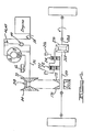
- Figure 4 is a schematic representation of the transmission of Figures 1, 2 and 3.
- In Figure 1
numeral 10 designates the end of the crankshaft for an internal combustion engine for a wheeled vehicle. The engine has an engine block to which one end of a first housing portion 12 is bolted. Located within the housing portion 12 is ahydrokinetic torque converter 14 which includes a bladed impeller 16, abladed turbine 18 and abladed stator 20. The impeller 16 includes animpeller housing 22 which enclosesturbine 18 andstator 20. The impeller housing is a closed housing defined in part byend wall 24 secured at itsmargin 26 to a peripheral shoulder for thehousing 22. - The radially outward part of the
wall 24 is secured at 28 to driveplate 30 which is secured at its hub to the end ofcrankshaft 10. - Turbine 18 includes a turbine hub 32 which is splined at 34 to
turbine shaft 36. It is splined also at 38 to the hub of adamper assembly 40, which is connected drivably at its radially outward periphery 42 to clutch plate 44. The radially outward margin of clutch plate 44 is provided with clutch friction material 46 which frictionally engagesclutch surface 48 formed on the radially outward portion ofhousing plate 24. The left hand side of the clutch plate 44 is subjected to the static pressure of the hydrokinetic fluid in the torus circuit of thehydrokinetic torque converter 14. The force developed by that pressure tends to engage the friction surfaces of the clutch plate 44 and the companion friction surface of thehousing plate 24 thus tending to lock the turbine to the impeller. - When the
space 50 located between clutch plate -44 and the inner surface of thehousing plate 24 is pressurized, the frictional connection established by the frictional contact of clutch plate 44 with thehousing plate 24 is interrupted and fluid flow occurs in a radial outward direction across the friction surfaces and to the interior of the torus circuit region. This disconnects the turbine from the impeller, and the turbine acts as a free converter in the usual fashion. -
Impeller housing 22 is supported by impeller sleeve shaft 52 journalled in bearing opening 54 in a positive displacement pump housing 56. The housing 56 forms a wall on the left hand side of the housing portion 12. It is secured toflange 58 on the housing portion 12. End plate 60 secured to the pump housing 56 includes a stator sleeve shaft 62 which is splined at 64 to the inner race of an overrunning coupling for thestator 20.Stator 20 thus is held against rotation in the direction opposite to the direction of movement of the impeller, but it permits freewheeling motion during operation of the converter in the coupling mode. - Fluid pressure for releasing the lockup clutch for the converter is supplied to the
space 50 through pressure supply passage 68 formed in theturbine shaft 36.Shaft 36 is splined at its left hand end to the hub 70 ofinput sheave portion 72, the spline connection being shown at 74. Theturbine shaft 36 thus rotates with thesheave portion 72. - The left hand side of the
sheave portion 72 is journalled by bearing 76 onbearing support 78 which forms a part oftransmission housing portion 80. The sheave assembly of which thesheave portion 72 forms a part is closed byhousing portion 80, the latter being bolted or otherwise secured at its margin 82 to the left hand side of the housing portion 12. - Another portion of the input sheave assembly is shown at 84. It is slidably positioned on the hub 70 for the
sheave portion 72. The hub portion for thesheave portion 84 is shown at 86 and a bearing 88 is provided between thehub portions 86 and 70 to permit relatively friction-free axial movement ofsheave portion 84 relative tosheave portion 72. - The hub 70 is splined at 90 to a sheave actuator housing 92. A sheave drive member 94 is secured by
bolts 96 to the housing 92. It is provided with a drum-shaped, axially extending part 98 which hasinternal splines 100. These splines engage drivably external spline teeth 102 formed on anaxial extension 104 of thesheave portion 84. - The inner margin of a
flexible diaphragm seal 106 is secured between the cooperating faces of the housing 92 and the drive member 98. The outer margin of theseal 106 is secured at 108 to the left hand margin of theextension 104 and is held in place by a clamp ring, as shown. The intermediate part of theseal 106 forms a flexible diaphragm that is engaged with the externalperipheral surface 110 of the housing 92 and the internal peripheral surface 112 of theextension 104. Upon relative movement of thesheave portion 84 relative to the housing 92, thediaphragm seal 106 rolls on theannular surfaces 110 and 112. - A second flexible diaphragm seal is provided at 114. The inner periphery of the diaphragm seal 114 is secured to the right hand end of the drive part 98 as shown at 116. A clamp ring is provided, as shown. The outer margin of the flexible diaphragm seal 114 is secured between the cooperating surfaces of
sheave portion 84 and an annular axially extending seal retainer 118. Retainer 118 is secured to thesheave portion 84 by clampingbolts 120. - The
space 122 on the left hand side of theflexible diaphragm seal 106 communicates throughfeed passage 124 with pressurefluid feed passage 126 formed in the housing 92.Passage 126 in turn communicates with radially extending passage 128, which communicates with pressure fluid delivery passage 130 extending along the axis of thesheave portion 72. Passage 130 is defined by a flow delivery tube extending from a central opening in the left hand side of the hub 70 to a central passage 132 inturbine shaft 36. The right hand end of passage 132 communicates with control pressure supply passage 134 in the pump cover plate 60. -
Sheave portion 72 is journalled by bearing 136 on stationarysleeve shaft extension 138 for the pump cover 60.Thrust washer 140 accommodates axial thrust forces acting on thesheave portion 72 and running seal 142 isolates the lubricating fluid supplied to thebearings 136 and 140 from the lubricationoil supply passage 144. Arotary oil seal 146 is located at the left hand side of the sheave hub 70 for isolating lubricating oil supplied to bearing 76 and to thrustbearing 148. - As seen in Figure 2, a
first output shaft 150 is mounted in the lower portion of the transmission assembly in parallel relationship with respect to the axis of the converter and the input sheave assembly. An output sheave sleeve shaft 152 surroundsoutput shaft 150. The left hand end of the sleeve shaft 152 is journalled by bearing 154 on theshaft 150. The left hand end of theshaft 150 is journalled at 156 in abearing recess 158 formed in the wall ofhousing 80. Shaft 152 is journalled also by bearing 160 received in bearing opening 162 formed insupport wall 164. This wall is secured at its periphery to the interior of thetransmission housing 166.Housing 166 in turn is secured bybolts 168 to thehousing 80, as seen in Figure 1. Thehousing 166 forms a part of converter housing 12. Preferably housing 12 andhousing 166 are formed as a single casting. - Output sheave sleeve shaft 152 is formed integrally with
output sheave portion 170. A companion output sheave portion 172 is slidably supported by bearing 174 on the shaft 152. Apressure actuator portion 176 is splined at 177 to the shaft 152 and extends radially outwardly. Anactuator portion 178 is secured bybolts 180 to theactuator portion 176, and it is provided with an axial extension 182.Internal spline teeth 184 are formed on theextension 178. These teeth mesh withexternal spline teeth 186 formed on extension 188 of the output sheave portion 172. A clampingforce spring 190 is disposed between the sheave portion 172 and theactuator portion 176 to establish a threshold clamping load on the output sheave assembly. - A flexible diaphragm seal 192 is secured at its inner margin to an
annular shoulder 194 on theactuator portion 176. Theinner margin 194 of the flexible diaphragm seal 192 is clamped between the mating surfaces of theactuator portion 176 and thedrive portion 178. The radially outward margin of the flexible diaphragm seal 192 is secured to the right hand end of extension 188 and is held in place preferably by a clamping ring 196. - The left end of the axially extending portion 182 of the
drive portion 178 has secured thereto the inner margin of a second flexible diaphragm seal for the output sheave assembly as shown at 198. The outer margin of thediaphragm seal 198 is secured to the cooperating surfaces ofsheave extension 200, which is bolted to the sheave portion 172 at a radially outward location by means of clamping bolts 202. The intermediate portion of thediaphragm seal 198 rides over the outer annular surface of axially extending portion 182 of thedrive member 178 and the inner annular surface ofextension 200. A pressure chamber 204 on the right hand side of diaphragm seal 192 and the left hand side ofdiaphragm seal 198 communicates with pressure feed passage 206. - The input sheave assembly is connected drivably to the output sheave assembly by a
drive belt 208.Belt 208, in the disclosed working embodiment of the invention, is a rubber belt having reinforcedsteel segments 210. It is formed with conical shaped sides that register with the cone surfaces of the inputsheave assembly portions sheave assembly portions 170 and 172. Assheave portion 84 is adjusted relative to thesheave portion 72,belt 208 increasing its effective pitch radius with respect to the input sheave assembly and this is accompanied by a corresponding decrease in the operating pitch radius of the output sheave assembly. Sheave portion 172 slides on sleeve shaft 152 in a right hand direction. When the speed ratio of the sheave drive increases in Figures 1 and 2 the sheave assemblies are shown in the maximum underdrive condition. - Torque transmitted from the input sheave assembly to the output sheave assembly is distributed through the shaft 152 to a
sun gear 210, which is common to reverseplanetary gear assembly 212 and the forward driveplanetary gear assembly 214. -
Planetary gear unit 212 includes aring gear 216, acarrier 218 andplanet pinions 220 journalled on thecarrier 218.Carrier 220 is adapted to be braked by afriction brake assembly 222, which comprises internally splined brake discs carried byspline portion 224 of thecarrier 218 and externally splined discs carried by the internally splinedportion 226 of thehousing 166. Bearingsupport wall 164 is provided with anannular cylinder 228 which receivesannular piston 230, the latter engaging brake discs for thebrake assembly 222 as fluid pressure is admitted to theannular cylinder 228. Piston return spring 232 disengages the brake discs of thebrake assembly 222 when fluid pressure is exhausted fromcylinder 228. -
Carrier 218 is journalled by bushing 234 on the bearingsupport wall 164.Ring gear 216 is connected tocarrier 236 forplanetary gear unit 214.Carrier 236 forms a part of, or is connected to,output shaft 238, which is splined at 240 todifferential carrier 242 as seen in Figure 3.Carrier 242 is straddle mounted bybearings end wall 248 forhousing 166 and indifferential housing 250, the latter being secured by bolts at itsmargin 252 to theend wall 248. -
Carrier 236 journalsplanetary pinions 253 which engagesun gear 210.Pinions 220 also engagesun gear 210. - Ring gear 254 is journalled on
output shaft 238 and is adapted to be braked by multipledisc friction brake 256.Brake 256 includes internally splined brake discs carried byring gear extension 258 and externally splined brake discs carried byhousing 166.Housing 166 andend wall 248 define acylinder 260 in which is positionedbrake actuator piston 262.Piston return spring 264 acts on thepiston 262 to disengage thebrake 256 when fluid pressure is exhausted from thecylinder 260. - A
second output shaft 266, as seen in Figure 3, extends to one axle shaft and is aligned with thecompanion axle shaft 150.Shaft 150 is connected todifferential side gear 268.Output shaft 266 is connected todifferential side gear 270, as seen in Figure 3, and both differential side gears engagedifferential pinions cross pin 276 in thedifferential carrier 242. - During operation of the transmission mechanism the infinitely variable sheave drive, during acceleration, operates in its maximum underdrive ratio and continues to develop torque which is distributed to the output shaft and to the planetary transmission until the converter coupling point is reached. At that time the lockup clutch is applied. A variation in ratio occurs as
sheave portion 84 is adjusted relative to sheaveportion 72 by admitting fluid pressure to the workingchamber 122. Similarly, sheave portion 172 of the output sheave assembly is adjusted relative to thesheave portion 170 as the input sheave assembly is adjusted. The clamping pressure is controlled by controlling the pressure in the working chamber 204. - With this design the drive spline 102 for the input sheave assembly and the
drive spline 186 for the output sheave assembly are located inside their respective sheave piston apply pressure cavities so that these drive splines are constantly lubricated thus permitting relatively friction free adjustments of thesheave portion 72 relative to sheaveportion 84 and sheave portion 172 relative to sheaveportion 170. In addition, the flexible diaphragm seals assure a dry environment for the belt. These features are in contrast to sliding servo actuators of the kind shown in the prior art patents discussed in the introductory portions of this specification. - The infinitely variable torque range is available for either forward or reverse drive. Reverse drive is obtained by engaging
reverse brake 222 and releasing forwardbrake 256. Forward drive is achieved by engagingbrake 256 and releasingbrake 222. - In addition to the foregoing features the transmission mechanism includes a planetary gear system that is isolated with respect to the flexible belt drive portion. This avoids contamination of the belt environment with transmission lubricating oil and it also permits belt replacement without complete disassembly of the transmission mechanism. Belt replacement can occur merely by disassembling the
housing portion 80 and removing the belt drive components on the input sheave assembly end of the belt drive without removing the output sheave assembly or the bearingsupport wall 164 for the planetary gearing.
Claims (5)
Applications Claiming Priority (2)
| Application Number | Priority Date | Filing Date | Title |
|---|---|---|---|
| US06/667,657 US4608032A (en) | 1984-11-02 | 1984-11-02 | Infinitely variable belt drive with low friction seals for the primary and secondary sheaves |
| US667657 | 1984-11-02 |
Publications (2)
| Publication Number | Publication Date |
|---|---|
| EP0180089A1 true EP0180089A1 (en) | 1986-05-07 |
| EP0180089B1 EP0180089B1 (en) | 1989-02-01 |
Family
ID=24679097
Family Applications (2)
| Application Number | Title | Priority Date | Filing Date |
|---|---|---|---|
| EP85306876A Withdrawn EP0180324A1 (en) | 1984-11-02 | 1985-09-27 | Infinitely variable belt drive |
| EP85113076A Expired EP0180089B1 (en) | 1984-11-02 | 1985-10-15 | Infinitely variable belt drive with low friction seals for the primary and secondary sheaves |
Family Applications Before (1)
| Application Number | Title | Priority Date | Filing Date |
|---|---|---|---|
| EP85306876A Withdrawn EP0180324A1 (en) | 1984-11-02 | 1985-09-27 | Infinitely variable belt drive |
Country Status (3)
| Country | Link |
|---|---|
| US (1) | US4608032A (en) |
| EP (2) | EP0180324A1 (en) |
| DE (1) | DE3568076D1 (en) |
Cited By (3)
| Publication number | Priority date | Publication date | Assignee | Title |
|---|---|---|---|---|
| EP0328166A1 (en) * | 1988-02-02 | 1989-08-16 | Van Doorne's Transmissie B.V. | Continuously variable transmission provided with a torque converter |
| EP0437157A1 (en) * | 1990-01-12 | 1991-07-17 | Société Canadienne POWERBLOC IBC Canada | Pulley for continuously variable transmission, with a torque transmitting membrane |
| NL1001756C2 (en) * | 1995-11-28 | 1997-05-30 | Doornes Transmissie Bv | Pulley. |
Families Citing this family (14)
| Publication number | Priority date | Publication date | Assignee | Title |
|---|---|---|---|---|
| US4772247A (en) * | 1986-09-11 | 1988-09-20 | Ford Motor Company | Integrated fixed drive belt sheaves for a continually variable transmission |
| US4881926A (en) * | 1987-12-04 | 1989-11-21 | Diesel Kiki Co., Ltd. | Stepless speed variator of a belt type |
| US4986398A (en) * | 1989-03-27 | 1991-01-22 | Luk Lamellen Und Kupplungsbau Gmbh | Torque converter clutch |
| US5931760A (en) * | 1997-09-29 | 1999-08-03 | Ford Global Technologies, Inc. | Dual mode continuously variable transmission having multiple torque input paths |
| US5961414A (en) * | 1997-09-29 | 1999-10-05 | Ford Global Technologies, Inc. | Dual mode continuously variable transmission having multiple torque input paths |
| US5941789A (en) * | 1998-03-19 | 1999-08-24 | Ford Global Technologies, Inc. | All wheel drive continuously variable transmission having dual mode operation |
| US6093125A (en) * | 1998-03-19 | 2000-07-25 | Ford Global Technologies, Inc. | All wheel drive continuously variable transmission having dual mode operation |
| US5916053A (en) * | 1998-03-19 | 1999-06-29 | Ford Global Technologies, Inc. | Dual mode operation continuously variable transmission having creeper low and reverse gears |
| US5888161A (en) * | 1998-03-19 | 1999-03-30 | Ford Global Technologies, Inc. | All wheel drive continuously variable transmission having dual mode operation |
| US5937711A (en) * | 1998-03-19 | 1999-08-17 | Ford Global Technologies, Inc. | All wheel drive continuously variable transmission having dual mode operation |
| US6106428A (en) * | 1998-03-23 | 2000-08-22 | Ford Global Technologies, Inc. | Compact dual mode continually variable transmission |
| JP4151607B2 (en) * | 2004-05-06 | 2008-09-17 | トヨタ自動車株式会社 | Belt type continuously variable transmission |
| KR101234655B1 (en) * | 2010-11-24 | 2013-02-19 | 기아자동차주식회사 | continuous variable transmission for use a vehicle |
| US9816594B2 (en) * | 2015-11-13 | 2017-11-14 | GM Global Technology Operations LLC | Twin axis twin-mode continuously variable transmission |
Citations (8)
| Publication number | Priority date | Publication date | Assignee | Title |
|---|---|---|---|---|
| GB833383A (en) * | 1956-11-07 | 1960-04-21 | Woods T B Sons Co | Improvements in variable-pitch sheaves with lubricating means |
| FR2362291A1 (en) * | 1976-08-21 | 1978-03-17 | Festo Maschf Stoll G | PNEUMATIC OR HYDRAULIC CYLINDER |
| GB2025545A (en) * | 1978-07-13 | 1980-01-23 | Fiat Ricerche | Transmission unit for a motor vehicle |
| EP0007137A1 (en) * | 1978-07-14 | 1980-01-23 | Van Doorne's Transmissie B.V. | Transmission provided with a variable V-belt transmission and a hydrodynamic transmission |
| DE2948195A1 (en) * | 1978-12-09 | 1980-06-26 | Piv Antrieb Reimers Kg Werner | TRANSMISSION AS MAIN DRIVE FOR A VEHICLE DRIVEN BY AN INTERNAL COMBUSTION ENGINE |
| GB2064683A (en) * | 1979-10-30 | 1981-06-17 | Aisin Warner | Automotive transmission |
| US4411590A (en) * | 1980-12-08 | 1983-10-25 | Reliance Electric Company | Control system for variable speed belt drives |
| GB2140106A (en) * | 1983-05-16 | 1984-11-21 | Valeo | Speed variator pulley |
Family Cites Families (9)
| Publication number | Priority date | Publication date | Assignee | Title |
|---|---|---|---|---|
| US2731534A (en) * | 1948-02-26 | 1956-01-17 | Taylor Winfield Corp | Fluid pressure actuator for machine components |
| US3244013A (en) * | 1964-08-13 | 1966-04-05 | Richard E Deschner | Diaphragm retaining structure for hydraulic control devices |
| US3478611A (en) * | 1968-07-15 | 1969-11-18 | Claude Venne | Variable speed drive assembly |
| DE1816950C3 (en) * | 1968-12-24 | 1971-06-03 | Piv Antrieb Reimers Kg Werner | Conical pulley belt drive |
| US3525289A (en) * | 1969-02-18 | 1970-08-25 | United Aircraft Corp | Pneumatic actuator |
| US4125037A (en) * | 1975-12-17 | 1978-11-14 | Gkn Transmissions Limited | Variable speed transmission means |
| US4425102A (en) * | 1980-09-26 | 1984-01-10 | Reliance Electric Company | Variable speed belt drive |
| GB2112105B (en) * | 1981-11-18 | 1985-09-11 | Aisin Seiki | Closing brake booster housing |
| JPS58207561A (en) * | 1982-05-27 | 1983-12-03 | Honda Motor Co Ltd | Automatic speed change pulley |
-
1984
- 1984-11-02 US US06/667,657 patent/US4608032A/en not_active Expired - Fee Related
-
1985
- 1985-09-27 EP EP85306876A patent/EP0180324A1/en not_active Withdrawn
- 1985-10-15 EP EP85113076A patent/EP0180089B1/en not_active Expired
- 1985-10-15 DE DE8585113076T patent/DE3568076D1/en not_active Expired
Patent Citations (8)
| Publication number | Priority date | Publication date | Assignee | Title |
|---|---|---|---|---|
| GB833383A (en) * | 1956-11-07 | 1960-04-21 | Woods T B Sons Co | Improvements in variable-pitch sheaves with lubricating means |
| FR2362291A1 (en) * | 1976-08-21 | 1978-03-17 | Festo Maschf Stoll G | PNEUMATIC OR HYDRAULIC CYLINDER |
| GB2025545A (en) * | 1978-07-13 | 1980-01-23 | Fiat Ricerche | Transmission unit for a motor vehicle |
| EP0007137A1 (en) * | 1978-07-14 | 1980-01-23 | Van Doorne's Transmissie B.V. | Transmission provided with a variable V-belt transmission and a hydrodynamic transmission |
| DE2948195A1 (en) * | 1978-12-09 | 1980-06-26 | Piv Antrieb Reimers Kg Werner | TRANSMISSION AS MAIN DRIVE FOR A VEHICLE DRIVEN BY AN INTERNAL COMBUSTION ENGINE |
| GB2064683A (en) * | 1979-10-30 | 1981-06-17 | Aisin Warner | Automotive transmission |
| US4411590A (en) * | 1980-12-08 | 1983-10-25 | Reliance Electric Company | Control system for variable speed belt drives |
| GB2140106A (en) * | 1983-05-16 | 1984-11-21 | Valeo | Speed variator pulley |
Cited By (6)
| Publication number | Priority date | Publication date | Assignee | Title |
|---|---|---|---|---|
| EP0328166A1 (en) * | 1988-02-02 | 1989-08-16 | Van Doorne's Transmissie B.V. | Continuously variable transmission provided with a torque converter |
| EP0437157A1 (en) * | 1990-01-12 | 1991-07-17 | Société Canadienne POWERBLOC IBC Canada | Pulley for continuously variable transmission, with a torque transmitting membrane |
| FR2657132A1 (en) * | 1990-01-12 | 1991-07-19 | Ibc Europ Eurl | SPEED DRIVE PULLEY EQUIPPED WITH A TRANSMISSION MEMBRANE. |
| NL1001756C2 (en) * | 1995-11-28 | 1997-05-30 | Doornes Transmissie Bv | Pulley. |
| EP0777070A1 (en) * | 1995-11-28 | 1997-06-04 | Van Doorne's Transmissie B.V. | Pulley |
| US5676612A (en) * | 1995-11-28 | 1997-10-14 | Van Doorne's Transmissie B.V. | Pulley |
Also Published As
| Publication number | Publication date |
|---|---|
| EP0180089B1 (en) | 1989-02-01 |
| DE3568076D1 (en) | 1989-03-09 |
| EP0180324A1 (en) | 1986-05-07 |
| US4608032A (en) | 1986-08-26 |
Similar Documents
| Publication | Publication Date | Title |
|---|---|---|
| US4608032A (en) | Infinitely variable belt drive with low friction seals for the primary and secondary sheaves | |
| US4467670A (en) | Belt drive continuously-variable speed automatic transmission | |
| US4938097A (en) | Four speed transaxle for automotive vehicles | |
| US4950213A (en) | Planetary gear transmission having an arrangement for efficient lubrication of planetary gears | |
| US4876920A (en) | Dual range infinitely variable transmission | |
| US4741422A (en) | Clutch assembly with a pressure balance chamber | |
| JP3097439B2 (en) | Oil passage structure for continuously variable transmission | |
| US4467669A (en) | Working fluid distributing system for a belt drive continuously-variable speed automatic transmission | |
| US4543852A (en) | Clutch assembly for a planetary forward reverse gear set | |
| US4955852A (en) | Planetary gear mechanism having means for accurate alignment of sun gear | |
| US4549447A (en) | Belt drive continuously-variable speed automatic transmission | |
| US4346622A (en) | Four speed transaxle with mid-position transfer drive | |
| EP0001839B1 (en) | A hydrokinetic torque transmission unit | |
| EP0038538A2 (en) | Four speed ratio transverse automatic transmission | |
| US4223569A (en) | Transverse transmission with parallel, coplanar axis | |
| US4455890A (en) | Overdrive device for automatic transmissions | |
| GB2030246A (en) | Hydromechanical automatic transmission | |
| EP0396911B1 (en) | Four speed overdrive inline transmission | |
| US4271721A (en) | Housing for front-drive automatic transmission for transverse engine of automotive vehicle | |
| US4267910A (en) | Clutch drum assembly for automatic power transmission | |
| US4760757A (en) | Continuously variable belt driven transmission for motor vehicles with a compact planetary gearing and clutch and brake assembly | |
| US5178027A (en) | Supporting structure for output shaft of automotive automatic power transmission | |
| US4028965A (en) | Multiple ratio power transmission mechanism adapted for improved engine fuel economy and high/low ratio traction | |
| US4613022A (en) | Torque converter one way lock-up clutch | |
| US3424031A (en) | Multiple speed ratio power transmission mechanism with a minimum deflection chain drive |
Legal Events
| Date | Code | Title | Description |
|---|---|---|---|
| PUAI | Public reference made under article 153(3) epc to a published international application that has entered the european phase |
Free format text: ORIGINAL CODE: 0009012 |
|
| AK | Designated contracting states |
Kind code of ref document: A1 Designated state(s): DE FR GB IT NL SE |
|
| 17P | Request for examination filed |
Effective date: 19860418 |
|
| 17Q | First examination report despatched |
Effective date: 19870605 |
|
| ITF | It: translation for a ep patent filed | ||
| GRAA | (expected) grant |
Free format text: ORIGINAL CODE: 0009210 |
|
| AK | Designated contracting states |
Kind code of ref document: B1 Designated state(s): DE FR GB IT NL SE |
|
| REF | Corresponds to: |
Ref document number: 3568076 Country of ref document: DE Date of ref document: 19890309 |
|
| ET | Fr: translation filed | ||
| PLBE | No opposition filed within time limit |
Free format text: ORIGINAL CODE: 0009261 |
|
| STAA | Information on the status of an ep patent application or granted ep patent |
Free format text: STATUS: NO OPPOSITION FILED WITHIN TIME LIMIT |
|
| 26N | No opposition filed | ||
| PGFP | Annual fee paid to national office [announced via postgrant information from national office to epo] |
Ref country code: SE Payment date: 19900928 Year of fee payment: 6 |
|
| ITTA | It: last paid annual fee | ||
| PGFP | Annual fee paid to national office [announced via postgrant information from national office to epo] |
Ref country code: NL Payment date: 19901031 Year of fee payment: 6 |
|
| PG25 | Lapsed in a contracting state [announced via postgrant information from national office to epo] |
Ref country code: SE Effective date: 19911016 |
|
| REG | Reference to a national code |
Ref country code: GB Ref legal event code: 746 |
|
| PG25 | Lapsed in a contracting state [announced via postgrant information from national office to epo] |
Ref country code: NL Effective date: 19920501 |
|
| REG | Reference to a national code |
Ref country code: FR Ref legal event code: DL |
|
| NLV4 | Nl: lapsed or anulled due to non-payment of the annual fee | ||
| PGFP | Annual fee paid to national office [announced via postgrant information from national office to epo] |
Ref country code: GB Payment date: 19931001 Year of fee payment: 9 |
|
| PGFP | Annual fee paid to national office [announced via postgrant information from national office to epo] |
Ref country code: DE Payment date: 19931007 Year of fee payment: 9 |
|
| PGFP | Annual fee paid to national office [announced via postgrant information from national office to epo] |
Ref country code: FR Payment date: 19931102 Year of fee payment: 9 |
|
| PG25 | Lapsed in a contracting state [announced via postgrant information from national office to epo] |
Ref country code: DE Effective date: 19940816 |
|
| PG25 | Lapsed in a contracting state [announced via postgrant information from national office to epo] |
Ref country code: GB Effective date: 19941015 |
|
| EUG | Se: european patent has lapsed |
Ref document number: 85113076.5 Effective date: 19920510 |
|
| GBPC | Gb: european patent ceased through non-payment of renewal fee |
Effective date: 19941015 |
|
| PG25 | Lapsed in a contracting state [announced via postgrant information from national office to epo] |
Ref country code: FR Effective date: 19950630 |
|
| REG | Reference to a national code |
Ref country code: FR Ref legal event code: ST |