EP0179643A2 - Magnetic tape players - Google Patents
Magnetic tape players Download PDFInfo
- Publication number
- EP0179643A2 EP0179643A2 EP85307590A EP85307590A EP0179643A2 EP 0179643 A2 EP0179643 A2 EP 0179643A2 EP 85307590 A EP85307590 A EP 85307590A EP 85307590 A EP85307590 A EP 85307590A EP 0179643 A2 EP0179643 A2 EP 0179643A2
- Authority
- EP
- European Patent Office
- Prior art keywords
- tape
- cam
- gear
- cam gear
- change lever
- Prior art date
- Legal status (The legal status is an assumption and is not a legal conclusion. Google has not performed a legal analysis and makes no representation as to the accuracy of the status listed.)
- Granted
Links
Images


Classifications
-
- G—PHYSICS
- G11—INFORMATION STORAGE
- G11B—INFORMATION STORAGE BASED ON RELATIVE MOVEMENT BETWEEN RECORD CARRIER AND TRANSDUCER
- G11B15/00—Driving, starting or stopping record carriers of filamentary or web form; Driving both such record carriers and heads; Guiding such record carriers or containers therefor; Control thereof; Control of operating function
- G11B15/02—Control of operating function, e.g. switching from recording to reproducing
-
- G—PHYSICS
- G11—INFORMATION STORAGE
- G11B—INFORMATION STORAGE BASED ON RELATIVE MOVEMENT BETWEEN RECORD CARRIER AND TRANSDUCER
- G11B5/00—Recording by magnetisation or demagnetisation of a record carrier; Reproducing by magnetic means; Record carriers therefor
- G11B5/48—Disposition or mounting of heads or head supports relative to record carriers ; arrangements of heads, e.g. for scanning the record carrier to increase the relative speed
- G11B5/54—Disposition or mounting of heads or head supports relative to record carriers ; arrangements of heads, e.g. for scanning the record carrier to increase the relative speed with provision for moving the head into or out of its operative position or across tracks
- G11B5/55—Track change, selection or acquisition by displacement of the head
- G11B5/5513—Specially adapted for transducing in both travelling directions of tape
- G11B5/5517—Controlled by automatic tape drive reversing arrangement
-
- G—PHYSICS
- G11—INFORMATION STORAGE
- G11B—INFORMATION STORAGE BASED ON RELATIVE MOVEMENT BETWEEN RECORD CARRIER AND TRANSDUCER
- G11B15/00—Driving, starting or stopping record carriers of filamentary or web form; Driving both such record carriers and heads; Guiding such record carriers or containers therefor; Control thereof; Control of operating function
- G11B15/02—Control of operating function, e.g. switching from recording to reproducing
- G11B15/05—Control of operating function, e.g. switching from recording to reproducing by sensing features present on or derived from record carrier or container
- G11B15/093—Control of operating function, e.g. switching from recording to reproducing by sensing features present on or derived from record carrier or container by sensing driving condition of record carrier, e.g. travel, tape tension
-
- G—PHYSICS
- G11—INFORMATION STORAGE
- G11B—INFORMATION STORAGE BASED ON RELATIVE MOVEMENT BETWEEN RECORD CARRIER AND TRANSDUCER
- G11B15/00—Driving, starting or stopping record carriers of filamentary or web form; Driving both such record carriers and heads; Guiding such record carriers or containers therefor; Control thereof; Control of operating function
- G11B15/18—Driving; Starting; Stopping; Arrangements for control or regulation thereof
- G11B15/44—Speed-changing arrangements; Reversing arrangements; Drive transfer means therefor
- G11B15/442—Control thereof
Landscapes
- Transmission Devices (AREA)
- Tape Measures (AREA)
Abstract
Description
- This invention relates to magnetic tape players.
- Various mechanisms have been proposed for use in cassette tape players to provide automatic reversing of the tape drive direction. Typically, the direction in which the tape is driven is changed automatically or reversed when the tape is unwound completely from a supply reel to a take-up reel during operation in a forward or playback mode of the tape player. Further, manual changing of the direction of tape drive at some point before detection of the tape end (end of the tape) during operation in the playback mode requires the addition of only a few relatively simple parts to such automatic reversing mechanisms. In general, a direction-changing button is mounted in such mechanisms so as to be operable manually for changing the tape drive from the normal direction to the reverse direction, and from the reverse direction to the normal direction, with both such direction changes occurring while the tape player remains in its playback mode established by a forward mode button being held in an operative or depressed position.
- In the above mechanism, although the tape drive direction should be changed reciprocally whenever the direction-changing button is operated or the tape end is detected, it is also necessary, for the convenience of the operator, that the tape be driven in the normal direction whenever the forward mode button is initially operated or depressed while the tape player is in a stop mode. Therefore, regardless of the direction in which the tape was being driven before return to the stop mode, it is necessary that the tape be driven in the normal direction when the forward mode button is operated or depressed with the tape player in the stop mode. This requires in addition, a so called "priority device", for example, as disclosed in our copending UK Patent Application Publication No. GB-A-2 148 580 filed 20 September 1984.
- In the mechanism disclosed in GB-A-2 148 580, a gear which has an eccentric thereon rotates once through 360 to cause a change lever to move to-and-fro whenever the tape end is detected or the direction-changing button is operated. A slider for changing the tape drive device and a lock lever for locking the slider at one position are reciprocally moved by the to-and-fro movement of the change lever. When the forward mode button resumes its inoperative or inactive position in response to establishing of the stop mode, the lock lever is returned to its inoperative position for releasing the slider. Therefore, the above-mentioned "priority device" function is achieved in a relatively easy way.
- However, the typical tape player of today is intended for portable use so that miniaturisation of its size is of importance. It is not desirable in such portable tape players to provide a mechanism including a change lever that is moved to-and-fro whenever a change of tape direction is to occur because this results in wasting of space in the player, especially for the movement of a change lever with a slanted posture as described in the above-identified application.
- Several attempts have been made to save space in a tape player by using a gear having a pair of diametrically opposed cutout portions or toothless gaps. For example, as shown in our US Patent No. US-A-3 976 263, an apparatus has been developed for controlling a tape drive device which, in its forward mode, can drive the tape only in a normal direction, and which has a change member movable between first and second positions in response to each turn of a gear through 1800. Although it may be possible to apply this type of gear to the existing mechanism for changing the tape drive direction in the playback mode, substantial modification of such mechanism is required, particularly in achieving the above-mentioned "priority device" function without undesirably increasing the space required therefor in the tape player.
- According to one aspect of the invention there is provided a magnetic tape player having a tape drive device selectively operative to drive a tape in normal and reverse directions in a forward mode of the tape player, and apparatus for controlling the tape drive device, said apparatus comprising: a rotatable cam gear having a toothed periphery with a pair of diametrically opposed gaps therein; a rotatable driving gear engageable with the toothed periphery of the cam gear for turning the cam gear through at least approximately 180° upon each engagement of the driving gear with the toothed periphery; a pair of diametrically opposed stopper projections rotatably coupled with the cam gear; a latch member mounted adjacent the cam gear and movable, between an engaged position, in which the latch member is engageable with one of the stopper projections for positioning the cam gear in a rest position with one of the gaps facing the driving gear, and a released position in which the latch member is disengaged from the stopper projections; a cam surface on the cam gear having a pair of diametrically opposed, radially enlarged portions; spring means engaging the cam surface and acting against one of the radially enlarged portions when a respective one 'of the gaps faces the driving gear for turning the cam gear from said rest position upon movement of the latch member to said released position; an eccentric member on the cam gear; a change lever" movable between first and second positions for causing operation of the tape drive device to drive the tape in the normal and reverse directions, respectively; a cam follower member engageable with the eccentric member and mounted pivotally on the change lever; a spring-loaded lock arm also pivotally mounted on the change lever and being movable between a normal operative position for locking the cam follower member relative to the change lever and an inoperative position in which the cam follower member is free to pivot relative to the change lever; a forward mode selecting member having an inactive position, in which the lock arm is displaced to said inoperative position thereof, and being movable to an active position for selecting said forward mode and releasing the lock arm to permit the lock arm to attain said normal operative position; and means responsive to pivoting of the cam follower member by the eccentric member when the lock arm is in said inoperative position for moving the latch member to said released position.
- According to a second aspect of the invention there is provided a magnetic tape player having a tape drive device selectively operative to drive a tape in normal and reverse directions in a forward mode of the tape player, and apparatus for controlling the tape drive device, said apparatus comprising: a rotatable cam gear having a toothed periphery with a pair of diametrically opposed gaps therein; a rotatable driving gear engageable with the toothed periphery of the cam gear for turning the cam gear through at least approximately 180° upon each engagement of the driving gear with the . toothed periphery; a pivot arm supporting the driving gear and being movable between an operative position in which the driving gear is engageable with the toothed periphery of the carn gear and an inoperative position holding the driving gear away from the toothed periphery; a pair of diametrically opposed stopper projections rotatably coupled with the cam gear; a latch member mounted adjacent said cam gear and movable between an engaged position, in which the latch member is engageable with one of the stopper projections for positioning the cam gear in a rest position with one of the gaps facing the driving gear, and a released position in which the latch member is disengaged from the stopper projections; an eccentric member on the cam gear; a change lever movable in opposite directions from a neutral position corresponding to an inoperative condition of the tape drive device to first and second operative positions for causing operation of the tape drive device in the normal and reverse directions, respectively, with the tape player in the forward mode; means that can be acted upon by the eccentric member for moving the change lever between the first and second operative positions in response to turning of the cam gear through 180°; a cam surface on the cam gear having a pair of diametrically opposed, radially enlarged portions; spring means engaging the cam surface and acting against one of the radially enlarged portions when a respective one of the gaps faces the driving gear for turning the cam gear from said rest position when the latch member is moved to said released position; and forward mode selecting means movable to an inoperative position in which the latch member is moved to said released position and the pivot arm is moved to said inoperative position.
- A preferred embodiment of the present invention described in detail below provides a mechanism for controlling a tape drive device in a magnetic tape player so as to change the direction in which a tape is driven, and which can satisfy the requirements noted above. Specifically, the mechanism has a "priority device" function, that is it can operate to drive a tape in the normal direction when the forward mode button is initially operated with the tape player in its stop mode, regardless of the direction in which the tape was driven before the stop mode was established. The preferred mechanism can be employed in a portable tape player and can provide automatic and manual reversing operation in the forward or playback mode.
- In accordance with the preferred embodiment of the present invention, the apparatus for controlling a tape drive device in a magnetic tape player so as to change the direction of tape drive comprises a cam gear having a pair of diametrically opposed toothless portions or gaps in its periphery, a driving gear engageable with the cam gear to turn the cam gear through 1800 upon each such engagement thereof, and a pair of stopper projections on the cam gear which are engageable selectively with a lock or latch member to position the cam gear with one of its gaps facing the driving gear. A pair of diametrically opposed, radially enlarged cam portions and an eccentric cam member also are provided on the cam gear. In order initially to turn the cam gear when the latch member is released from engagement with one of the stopper projections, bias spring means acts against one of the radially enlarged cam portions when one of the toothless portions of the cam gear faces the driving gear. A change lever is mounted to move between first and second positions for selecting the normal and reverse directions, respectively, of the tape drive. A cam follower member and a spring-loaded lock arm are both pivotally mounted on the change lever, with the cam follower member contacting the eccentric cam member, and the spring-loaded lock arm is movable to its operative position for locking the cam follower member at a fixed angle relative to the change lever in response to actuation of a mode selecting lever for establishing the forward or playback mode. When the cam follower member is locked relative to the change lever, the change lever is moved from one to another of its first and second positions for changing the direction in which the tape is driven in response to each turn of the cam gear through 180°. When the cam follower member is pivoted in response to initial rotation of the eccentric cam member without being secured at the fixed angle relative to the change lever by the lock arm, for example when the forward mode is established after the stop mode, the change lever remains at rest and the cam follower member releases the latch member from engagement with one of the stopper projections and permits further turning of the cam gear during which the cam follower member is locked relative to the change lever and the resulting pivotal movement of the change lever causes driving of the tape in the normal direction for the forward mode established from the stop mode. In other words, the change lever is moved reciprocally between first and second positions for changing the direction in which the tape is driven only when the cam follower member is locked by the spring-loaded luck arm in a fixed angular position relative to the change lever.
- The invention will now be further described, by way of illustrative and non-limiting example, with reference to the accompanying drawings, in which:
- Figure 1 is a plan view of a tape player according to one embodiment of the present invention having an apparatus or mechanism for controlling the tape drive, the player being shown in a stop mode;
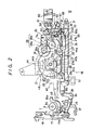
- Figure 2 is a plan view similar to that of Figure 1, but with a number of the elements removed to more clearly show the condition of the remaining elements with the tape player in a forward mode and arranged for driving the tape in a normal direction;
- Figure 3 is another plan view similar to that of Figure 1, but with a number of the elements removed to better illustrate movements effected for changing the direction of the tape drive from the normal direction to a reverse direction while the tape player is in its forward or playback mode;
- Figures 4 and 5 are enlarged, fragmentary plan views showing elements of Figures 1 and 2 constituting an automatic mechanism for changing the direction of the tape drive at the tape end;
- Figure 6 is a plan view of an automatic mechanism for stopping the driving of the tape at the tape end, that is, for automatic change-over to the stop mode from the playback mode of the player;
- Figure 7 is an exploded perspective view of a change lever, a spring frame, a cam follower member and a spring-loaded lock arm of the player embodying the invention, such elements being shown disassembled from each other;
- Figure 8 is an elevational view of a magnetic head and its supporting structure in a cassette holder of the tape player embodying the invention; and
- Figure 9 is a perspective view of the elements shown in Figure 8, but with the cassette holder shown in a tilted or open position.
- Figure 1 shows a magnetic tape player in which a pair of reel tables 1 and 2 are suitably rotatably mounted and
reel spindles Reel gears pinch rollers pivoted support arms capstans - A
forward lever 16 is moved in the direction of an arrow shown in Figure 2, in response to actuation of a forward button (not shown), and is held in its operative position by alock plate 17. A forwardmode selecting mechanism 18 will now be described in detail with reference to Fiqure 2, in which acam gear 19 is shown to have a pair of toothless portions orgaps cam gear 19 has afirst cam surface 20 and asecond cam surface 21 formed integrally therewith on one side of thecam gear 19. Acam pin 22 extends from the other side of thecam gear 19 at an eccentric position. As shown most clearly in Figures 4 and 5, thecam surface 20 has a pair of diametrically opposedstopper projections second cam surface 21 is generally diamond-shaped to present opposedpointed surface portions toothless portions cam gear 19 is mounted rotatably on afixed axle 23. - Returning to Figure 2, it will be seen that a
pivot lever 24 is mounted pivotally intermediate its ends on a fixedpivot pin 25, and adriving gear 26 is mounted rotatably on one end of thelever 24 adjacent thecam gear 19. Thedriving gear 26 includes afirst gear 26a of relatively large diameter engageable with aflywheel gear 7a integral with thecapstan 7, and asecond gear 26b of relatively small diameter which is engageable with thecam gear 19. The other end portion of thepivot lever 24 is branched to provide afirst arm 24a and a second arm 24b. A lock lever orlatch member 27 is mounted pivotally on a fixedpin 28. Aclaw 27a is formed at one end of thelock lever 27 to engage with one of thestopper projections other end 27b of thelever 27 is in contact with thefirst arm 24a of the pivot lever 24 (Figure 2). Oneactuator arm 29 of a forked spring engages thelock lever 27 and urges the latter in the clockwise direction for contact of theclaw 27a with the periphery of thefirst cam surface 20, and anotherarm 30 of the forked spring is in contact with the periphery of the second cam surface 21 (Figures 2 and 4). Thepivot lever 24 is urged to turn in the anticlockwise direction by aspring 33, so that the second arm 24b thereof makes contact with apin 32 extending from a transverselymovable slider 31. An end of theslider 31 is connected to one end of an L-shaped lever 35 which is mounted pivotally on a fixedpin 34. The other end of the L-shaped lever 35 is in contact with abent portion 36 of the forward lever 16 (Figure 2). A pivotally mounteddirection changing lever 37 is arranged to be turned in the direction of an arrow d in Figure 2 in response to manual actuation of a direction-change button (not shown) when the operator wants to change the direction of the tape drive before the tape end is detected during operation in the playback mode. - A
tape drive mechanism 38 is shown in Figure 3 to comprise achange lever 40 which cooperates with the above-described forwardmode selecting mechanism 18 to rotate selectively one of the reel tables I and 2 and to move selectively one of thepinch rollers capstans change lever 40 also is operative to change an azimuthadjust device 15 which will be described later with reference to Figures 8 and 9. - The
change lever 40 is mounted pivotally on a fixedpin 39, and aspring frame 43 is attached to oneend portion 40a of thelever 40 to move apulley gear 42 into selective engagement with thereel gear 6 or with anintermediate gear 41 which is always meshed with thereel gear 5. A U-shaped cam follower lever 44 (Figure 7) is mounted pivotally on thechange lever 40 by a rivet pin 45 (Figure 3) and is urged to rotate in the anticlockwise direction in Figure 3 by aplate spring 46 extending from thespring frame 43. Alock arm 48 having an extendedspring portion 48a is mounted pivotally on the change lever by therivet pin 47 and is biased by thespring portion 48a in the clockwise direction in Figure 3 so as to cause abent portion 48b of thelock arm 48 to hold aclaw 44c on thelever 44. Therefore, against the force of theplate spring 46, thecam follower lever 44 is locked by thelock arm 48 in a fixed position relative to thechange lever 40 where onearm 44a of thecam follower lever 44 is overlapped by anextended arm 40b on thechange lever 40. Figure 7 shows details of thechange lever 40,spring frame 43,cam follower lever 44 and lockarm 48 when disassembled from each other. - A bell-
crank lever 50 is shown in Figure 1 to be rotatab'y mounted on a fixed pin 49, and to be actuabie at one end by thearm 44a so that the other end of the bell-crank lever 50 acts on anose 27c of thelock lever 27. Therefore, theclaw 27a of thelock lever 27 is moved away from one of theprojections cam follower lever 44 is pivoted in the anticlockwise direction. On the other hand, thelock arm 48 is turned in the anticlockwise direction against the force of its spring arm 48d by anend 16a of an arm extended from theforward lever 16 when the latter is In its inoperative position as shown in Figure 1. - When the
change lever 40 is turned in the clockwise direction around thepin 39, theextended arm 40b causes anintermediate lever 52 pivoted on apin 54 to rock in an anticlockwise direction (Figure 3), by virtue of which thepinch roller 9 is moved against thecapstan 7 to establish the forward mode with the tape being driven in the normal direction. On the other hand, when thechange lever 40 is turned in the anticlockwise direction, anextended arm 40c angularly moves anintermediate lever 53 about apivot pin 55 in the clockwise direction so that thepinch roller 10 is moved by thelever 53 into contact with thecapstan 8 to drive the tape in a reverse direction while the player remains in its forward mode. - In the stop mode of the tape player, both the pinch
roller support arms pinch rollers capstans arms intermediate levers arms change lever 40 is held in a neutral position. In this mode, thepulley gear 42 is positioned away from thereel gear 6 and theintermediate gear 41 and, as noted above, thepinch rollers capstans - An
automatic mechanism 56 which operates to detect a tape end is shown in Figures 1,3,4 and 6 to comprise asolenoid 60 which is suitably energised momentarily at a time when thereel gear 6 stops rotating to cause interruption of a signal from aswitch 59 associated with thespindle 4. Anarmature 61 formed of a permanent magnet is attracted to the core of thesolenoid 60 when the solenoid is de-energised, as shown in Figures 1 and 2. A magnetic field is generated momentarily by a core of thesolenoid 60 in response to energising of the solenoid and acts to drive thearmature 61 away from thesolenoid 60 so that acontrol lever 58 pivoted on a fixedpin 57 and connected to thearmature 61 then can be rotated in the anticlockwise direction by the force of atorsion spring 66. Thespring 66 is mounted on the fixedpin 57 and acts at its end against the chassis and apin 64 on the lever 58 (Figure 4). Rotation of thecontrol lever 58 in the anticlockwise direction causes an end of akick lever 63 pivoted on thepin 64 to be moved to the position shown by dotted lines in Figure 4, in which thekick lever 63 extends into the orbit of aprojection 62 extending radially from the hub of theflywheel gear 7a rotating with thecapstan 7. Therefore, thekick lever 63 is propelled angularly by theprojection 62 in the clockwise direction about thepin 64, and anintermediate lever 68 pivoted on a fixedpin 67 is turned in the clockwise direction by thekick lever 63 and turns thelock lever 27 in the anticlockwise direction so that theclaw 27a thereof is moved away from thestopper projection spring arm 29. Areturn lever 69 is mounted rotatably on thepin 28 to return thecontrol lever 68 to its initial position in which thearmature 61 engages the core of the solenoid 60 (Figure 5). More particularly, acam follower wall 69a formed at an end of thereturn lever 69 is acted upon by one of thepointed surface portions 21a and 2]b of thecam 21 upon rotation of thecam gear 19, as shown in Figure 5. Anotherend 69b of thereturn lever 69 is received by abent portion 65a formed from awall 65 on thecontrol lever 58. - An automatic shut-off
mechanism 70 which operates automatically to establish a stop mode of the tape player upon detection of the tape end will now be described with reference to Figure 6. A shut-offgear segment 71 is mounted pivotally on apin 71a carried by theforward lever 16 and is urged angularly by a spring (not shown) to move to the position shown in Figure 2, that is, away from aflywheel gear 8a which is formed around and rotatable with thecapstan 8. Alever 73 which is pivoted on apin 72 on the chassis is in contact with the shut-offgear segment 71 at one end thereof (Figure 6). Acrank lever 74 is mounted pivotally on a fixedpin 75 and has one end pivotally connected to aslider 76. Aspring 80 urges theslider 76 towards the left in Figure 6 so that the other end of thecrank lever 75 is urged downwardly into contact with theintermediate lever 68. Aselect lever 78 is mounted pivotally on a fixedpin 77 and is locked by aslide knob 79 between a first position shown by solid lines and a second position shown by dotted lin-s in Figure 6. Theselect lever 78 provides aguide 78a for theslider 76 so that, in response to displacement of thelever 78 to its first and second positions, theslider 76 is disposed in an operative position shown by solid lines or in an inoperative position shown by dotted lines. When theslider 76 is in its operative position, End thereof remote frorn thecrank lever 74 is engageable with thelever 73. In that case, when themechanism 56 detects a tape end, the movement of itsintermediate lever 68 against thecrank lever 74 causes theslider 76 to move towards the right for rocking thelever 73 in a clockwise direction to move the shut-offgear segment 71 into meshing engagernent with theflywheel gear 8a, as shown in Figure 6. - Figures 8 and 9 show a
cassette holder 13 supported pivotally on achassis 12 by a suitable pivot structure (not shown) so as to be movable manually from a closed position shown in Figure 8 to an opened or tilted position at which a tape cassette can be inserted or removed. Abase plate 14 is mounted pivotally in thecassette holder 13 so that amagnetic head 11 supported on thebase plate 14 can be moved to different positions for the playback mode and stop mode of the player. Although the detailed structure thereof is not shown in the drawings, an azimuth adjustmechanism 15 is provided between thernaqnelic head 11 and thebase plate 14. As is well known, an azimuth angle of a magnetic tape path will change slightly in accordance with a change in the direction in which the tape is running. Therefore, in response to changes in the position of acontrol pin 15a, the azimuth adjustmechanism 15 acts to change slightly the azimuth angle of themagnetic head 11. To change the position of thecontrol pin 15a, anactuator portion 51 is formed at the end of anarm 40d of the change lever 40 (Figures 7 to 9). Theactuator portion 51 includes a pair ofinclined plates slot 51a in which thecontrol pin 15a is inserted in the closed position of the cassette holder 13 (Figure 8). - The operation of the above-described embodiment of the invention is as follows:
- For establishing a forward mode with the tape driven in the normal direction, the
forward lever 16 is moved from the position shown in Figure 1 to its operative position shown in Figure 2, in which it is retained by thelock plate 17. By virtue of such movement of theforward lever 16, a switch (not shown) suitably is turned on for operating a motor by which thecapstans pulley gear 42 are rotated. Further, themagnetic head 11 is moved suitably into a tape cassette inserted in thecassette holder 13. At the ssme time, in response to movement of theforward lever 16 to its operative position, the L-shapedlever 35 is turned in the direction of an arrow a (Figure 2), theslider 31 is moved in the direction of an arrow b (Figure 2), and thepivot lever 24 is turned in the direction of an arrow c (Figure 2), with all of these movements being powered by thespring 33 connected to thelever 24. As a result of such movement of thelever 24, thelarge gear 26a is meshed with theflywheel gear 7a which is rotating together with thecapstan 7. Since a toothed portion of thecam gear 19 faces thedriving gear 26 when the player is in its stop mode, as shown in Figure 1, thesmall gear 26b drives thecam gear 19 to rotate the latter at initiation of the forward mode. When thecam gear 19 is rotated to a certain angular position shown in Figure 2, theclaw 27a of the lock lever orlatch member 27 makes contacts with thestopper projection 20a to stop thecam gear 19 and keep it at this position where a toothless portion orgap 19a faces thesmall gear 26b. - During such turning of the
cam gear 19 to that predetermined or certain angular position, thepin 22 of thecam gear 19 pushes against the side surface of theextended arm 40b of the change le\.er 40, whereby thechange lever 40 is turned in the clockwise direction around thepin 39 in Figure 3. Therefore, thepulley gear 42 is moved by thespring frame 43 so as to engage with thereel gear 6, and theintermediate lever 52 is rocked by theextended arm 40b in the anticlockwise direction in Figure 3 so as to cause thepinch roller 9 to make contact with thecapstan 7. Further, thecontrol pin 15a shown in Figure 8 is moved to the left by theactuator portion 51 of thechange lever 40 to adjust themagnetic head 11 to the posture corresponding to the normal direction of tape movement. Thus, establishment of the forward mode in the normal direction is completed. - The operation for manually changing the direction in which the tape is driven will now be described.
- When a direction button (not shown) is operated at any time during operation in the forward mode with the tape being driven in the normal direction, the direction changing lever 37 (Figure 2) is turned in the direction of the arrow d. As a result thereof, the L-shaped
lever 35 is rotated in the anticlockwise direction opposite to the arrow a and theslider 31 is moved in the direction opposite to the arrow b. Thepin 32 on theslider 31 pushes the arm 24b of thepivot lever 24 so as to turn it in the direction opposite to the arrow c against the force of thespring 33. Therefore, thearm 24a of thelever 24 pushes theend 27b of thelock lever 27 to turn the latter in the anticlockwise direction around thepin 28. Accordingly, theflaw 27a moves away from thestopper projection 20a and then theactuator arm 30 of the forked spring in contact with thepointed surface portion 21b of thecam surface 21 can turn thecam gear 19 slightly to move thegap 19a away from thegear 26b. - Upon release of the manual pressure from the direction button (not shown), the
direction lever 37 can rock in the direction opposite to the arrow d in Figure 2. Then, the L-shapedlever 35,slider 31 andpivot lever 24 can be moved in the directions of the arrows a,b and c, respectively, by the force of thespring 33. In response to such movement of thepivot lever 24, thesmall gear 26b is meshed with thecam gear 19 again and drives it to turn through a certain angle, that is, until thestopper projection 20b is engaged by the claw 27d and thetoothless portion 19b of thegear 19 faces thesmall gear 26b. - As shown in Figure 3, during such turning of the
cam gear 19, theeccentric pin 22 thereon moves from the position shown in solid lines to the position shown in dotted lines at 22'. At this time, thecam follower lever 44 is locked by thelock arm 48 and unable to pivot around thepin 45 relative to thechange lever 40. Therefore, when theeccentric pin 22, in moving to the position 22', pushes against thearm 44b of thelever 44, thechange lever 40 is turned in the anticlockwise direction around thepin 39, so that thepulley gear 42 is moved to the left by thespring frame 43 so as to engage thegear 42 with theintermediate gear 41. Such turning of thechange lever 40 further causes rocking of theintermediate lever 53 in the clockwise direction about thepin 55 by means of thearm 40c so as to cause thepinch roller 10 to contact thecapstan 8, and thecontrol pin 15a is moved to the right by theactuator portion 51 of thechange lever 40 to adjust themagnetic head 11 to the posture corresponding to tape drive in the reverse direction. Changing of the direction of tape drive from the normal to the reverse direction thereby is completed. - The above-described direction-changing operation may be initiated manually at any time before the tape end is detected during operation in the forward mode with the tape being driven in either direction. However, upon detection of the tape end, the direction-changing operation is performed autornatically as described below in conjunction with Figures 4 and 5. As previously mentioned, the
solenoid 60 is energised momentarily when thereel gear 6 stops rotating and, as a result thereof, the signal from the switch 59 (Fioure 3) no longer appears. The magnetic field generated momentarily from the core of thesolenoid 60 acts to drive thearmature 61 away from thesolenoid 60 so that thecontrol lever 58 is turned in the anticlockwise direction by the force of thespring 66. In response to such turning of thecontrol lever 58, the end of thekick lever 63 is moved to the position shown by dotted lines In Figure 4, in which it projects into the orbit of theprojection 62. Thereupon, thekick lever 63 is turned about thepin 64 in the clockwise direction to the position shown in full lines in Figure 4 by the action of theprojection 62, and theintermediate lever 68 is rocked in the clockwise direction by thelever 63 so that theclaw 27a of thelock lever 27 is moved away from thestopper projection spring arm 29. Then, thecam gear 19 is rotated slightly by the force of thespring arm 30 on thecam surface 21 and thegear 19 is meshed with thesmall gear 26b which remains in the position shown in dotted lines in Figure 4. Thereafter, the same operations as described previously will be performed for changing the direction of tape drive from the normal direction to the reverse direction. - During the turning of the
cam gear 19 by which the change of the tape drive direction is effected, thecam follower wall 69a of thereturn lever 69 is pushed by the pointedsurface portion cam surface 21 so that thearm 69b moves in the direction of the arrow shown in Figure 5 and acts against thewall 65 of thecontrol lever 68 for turning the control lever clockwise about thepin 57. When thecontrol lever 58 thereby is moved back to its initial position shown in Figure 5 against the force of thespring 66, the magnetisedarmature 61 again will be in contact with the core of thesolenoid 60 so as to hold thekick lever 63 out of the orbit of theprojection 62. - For the above-described automatic changing mode of operation, the
slide knob 79 should be located at the position indicated in dotted lines in Figure 6 to move the free end of theslider 76 downwardly away from engagement with thelever 73. The further change of the tape direction from the reverse direction back to the normal direction can be effected by manual actuation of thedirection lever 37 before detection of the tape end, or by automatic operation upon detection of the tape end with the player in its forward mode and the tape being driven in the reverse direction. - The automatic shut-off operation for changing the player from its forward mode with the tape being driven in the norrnal or reverse direction to the stop mode upon the detection of the tape end is as follows:
- To achieve the automatic shut-off operation, the
slide knob 79 is preset in the position shown in solid lines in Figure 6. - The momentary energising of
solenoid 60, and the movement of thearmature 61,control lever 58,kick lever 63, and intermediate lever 6θ upon the detection of the tape end, are exactly the same as mentioned previously in the description of the automatic reversing operation. Thus, upon detection of the tape end, thecrank lever 74 is turned in the anticlockwise direction about thepin 75 so that theslider 76 is moved to the right against the force of thespring 80. Thelever 73, being engageable with the end of theslider 76, is turned in the clockwise direction about thepin 72 so as to push the shut-offgear segment 71 into meshing engagement with theflywheel gear 8a. The shut-offgear segment 71, rotated further by theflywheel gear 8a, acts to kick thelock plate 17 to its inoperative or released position, so that theforward lever 16 is free to be returned to its inoperative position (Figure 1) by a return spring (not shown). - Such return of the
forward lever 16 to its inoperative position, from the condition shown in Figure 2, causes turning of the L-shapedlever 36 in the direction opposite to the arrow a, and theslider 31 thereby is moved in the direction opposite to the arrow b, whereupon thelever 35 and slide 31 are retained in the positions shown in Figure 1, which are characteristic of the stop mode. Thepin 32 on theslide 31 acts against the arm 24b of thepivot lever 24 to turn the pivot lever in the direction opposite to the arrow c in Figure 2 to the position shown in Figure 1, which is characteristic of the stop mode. In such position of thepivot lever 24, thedriving gear 26 is held away from thecam gear 19 andflywheel gear 7a. Therefore, even though theflywheel gear 7a is rotated in the fast-forward and rewind modes of the player, the retention of thepivot lever 24 in the position of Figure 1 for such modes ensures that thecam gear 19 will not be rotated. - When the
pivot lever 24 is turned to the position of Figure 1 for the stop mode, thearm 24a in contact with theend 27b of thelock lever 27 moves the lock lever in the anticlockwise direction around thepin 28 to keep theclaw 27a away from thestopper projection claw 27a from thestopper projection cam gear 19 is turned slightly by the force of thespring arm 30 against thepointed surface cam gear 19 will fare thesmall gear 26b and thechange lever 40 will be moved to its neutral position because thecam pin 22 will be moved away from thearm 40b. In response to the movement of thechange lever 40 to its neutral position, thepulley gear 42 will be held in an inoperative position (Figure 1) in which thegear 42 is out of engagement with both thereel gear 6 and theintermediate gear 41, and both thepinch rollers capstans slide 31 to its stop mode position causes thepin 32 thereon to push thebent portion 65a of thecontrol lever 58 for pivoting the control lever against the force of thespring 66 and thereby returning the magnetisedarmature 61 into contact with the core of thesolenoid 60. - Finally, the operation of the above-described embodiment of the invention in achieving the function of a "priority device" will be described. By reason of the "priority device" function, the tape is driven in the normal direction whenever the forward mode button is actuated with the player in its stop mode, regardless of whether the tape was being driven in the normal or reverse direction before the stop mode was established. As previously mentioned in the description of the automatic shut-off mode, when the
forward lever 16 is returned to its inoperative position from the condition shown in Figure 2, which shows the forward mode with the tape driven in the normal direction, thecam gear 19 is rotated slightly by the force of thespring arm 30, and thechange lever 40 is moved to its neutral position. In this stop mode, because thelock arm 48 is locked in its inoperative position by the return (or downward) movement of theend 16a of theforward lever 16, thecam follower lever 44 is also turned slightly by the force of thespring 46. - When the forward button is actuated again with the player in the stop mode, the
eccentric pin 22 on thecam gear 19 will act, in response to turning of the cam gear, to push thearm 44b of thecam follower lever 44. Even though thelock arm 48 will return to its operative position upon the movement of theend 16a of theforward lever 16 coincident with movement of the forward lever to its operative position (Figure 2), thecam follower lever 44 will not be locked relative to thechange lever 40 by L':e lockarm 48, but will be pivoted about thepin 45 relative to thechange lever 40 which therefore will remain in its neutral position. Accordingly, no change will occur in thetape drive mechanism 38. However, the crank lever 50 (shown in Figure 1) will be locked by the pivoted movement of thearm 44a and will act on thenose 27c of thelock lever 27 so as to cause theclaw 27a to move away from thestopper projection 20b. - Upon further turning of the
cam gear 19 by thesmall gear 26b, theeccentric pin 22 is moved further into contact with thearm 44a of thecam follower lever 44 to pivot thelever 44 about thepin 45 relative to thechange lever 40 against the force of thespring 46. When thearm 44a of thecam follower lever 44 thereby is made to overlap thearm 40b of thechange lever 40, theclaw 44c then will be locked by thelock arm 48, and thechange lever 40 thereafter will be pivoted about thepin 39 in the clockwise direction and will be held at the position it occupies when theclaw 27a of thelock lever 27 contacts thestopper projection 20a. Thereby, the forward mode with tape drive in the normal direction will be established. - On the other hand, if the stop mode is established at a time when the player is in the forward mode with the tape being driven in the reverse direction, the
pin 22 on thecam gear 19 will be located at the position shown in Figure 1 after the slight rotation caused by thespring arm 30. Then, in response to actuation of theforward lever 16, thecam gear 19 will be rotated and thepin 22 will be moved therewith into contact with thearm 44a of thecam follower lever 44. By virtue of such movement of thepin 22, thecam follower lever 44 will be locked relative to thechange lever 40 by thelock arm 48 and, therefore, thechange lever 40 will be held at its pivoted position when thecam gear 19 is locked by thelock lever 27. - As described above, by reason of the "priority device" function a tape will be driven in the normal direction whenever the
forward lever 16 is operated with the player in the stop mode, regardless of the direction in which the tape was driven before establishment of the stop mode.
Claims (16)
Applications Claiming Priority (2)
| Application Number | Priority Date | Filing Date | Title |
|---|---|---|---|
| JP220720/84 | 1984-10-20 | ||
| JP59220720A JPS61104354A (en) | 1984-10-20 | 1984-10-20 | Tape recorder |
Publications (3)
| Publication Number | Publication Date |
|---|---|
| EP0179643A2 true EP0179643A2 (en) | 1986-04-30 |
| EP0179643A3 EP0179643A3 (en) | 1987-08-19 |
| EP0179643B1 EP0179643B1 (en) | 1991-01-23 |
Family
ID=16755457
Family Applications (1)
| Application Number | Title | Priority Date | Filing Date |
|---|---|---|---|
| EP85307590A Expired - Lifetime EP0179643B1 (en) | 1984-10-20 | 1985-10-21 | Magnetic tape players |
Country Status (7)
| Country | Link |
|---|---|
| US (1) | US4620242A (en) |
| EP (1) | EP0179643B1 (en) |
| JP (1) | JPS61104354A (en) |
| KR (1) | KR860003595A (en) |
| CN (1) | CN85107556A (en) |
| CA (1) | CA1269754A (en) |
| DE (1) | DE3581479D1 (en) |
Cited By (1)
| Publication number | Priority date | Publication date | Assignee | Title |
|---|---|---|---|---|
| WO1995014461A1 (en) * | 1993-11-23 | 1995-06-01 | Cambridge Neuroscience, Inc. | Therapeutic substituted guanidines |
Families Citing this family (3)
| Publication number | Priority date | Publication date | Assignee | Title |
|---|---|---|---|---|
| US4799116A (en) * | 1985-09-09 | 1989-01-17 | Sony Corporation | Apparatus for controlling an auto-reverse tape recorder having a mode-changing mechanism |
| JPH0614297Y2 (en) * | 1988-06-02 | 1994-04-13 | タナシン電機株式会社 | Tape drive direction controller for auto-reverse type tape recorder |
| DE19602741A1 (en) * | 1996-01-26 | 1997-07-31 | Philips Patentverwaltung | Reverse tape drive with a switching device |
Citations (5)
| Publication number | Priority date | Publication date | Assignee | Title |
|---|---|---|---|---|
| DE2446461A1 (en) * | 1973-10-02 | 1975-04-24 | Shinwa Shoko Co | AUTOMATIC REVERSAL OR RETURN DEVICE FOR CASSETTE TAPE RECORDING OR - PLAYBACK DEVICES |
| US3976263A (en) * | 1974-10-29 | 1976-08-24 | Technical Incorporated | Operating system in a magnetic tape reproducer and recorder |
| JPS5894152U (en) * | 1981-12-18 | 1983-06-25 | アルプス電気株式会社 | Auto-reverse mechanism of tape recorder |
| JPS5994270A (en) * | 1982-11-19 | 1984-05-30 | Toshiba Corp | Cassette tape recorder |
| FR2538151A1 (en) * | 1982-12-20 | 1984-06-22 | Clarion Co Ltd | REPRODUCER OF RECORDED BANDS |
Family Cites Families (2)
| Publication number | Priority date | Publication date | Assignee | Title |
|---|---|---|---|---|
| JPS6021418B2 (en) * | 1977-11-19 | 1985-05-27 | ソニー株式会社 | Recording/playback device |
| JPH0670863B2 (en) * | 1983-12-30 | 1994-09-07 | シャープ株式会社 | Reverse type tape recorder transport |
-
1984
- 1984-10-20 JP JP59220720A patent/JPS61104354A/en active Pending
-
1985
- 1985-10-16 US US06/788,113 patent/US4620242A/en not_active Expired - Fee Related
- 1985-10-17 CA CA000493188A patent/CA1269754A/en not_active Expired - Lifetime
- 1985-10-18 KR KR1019850007679A patent/KR860003595A/en not_active Application Discontinuation
- 1985-10-18 CN CN198585107556A patent/CN85107556A/en active Pending
- 1985-10-21 DE DE8585307590T patent/DE3581479D1/en not_active Expired - Lifetime
- 1985-10-21 EP EP85307590A patent/EP0179643B1/en not_active Expired - Lifetime
Patent Citations (5)
| Publication number | Priority date | Publication date | Assignee | Title |
|---|---|---|---|---|
| DE2446461A1 (en) * | 1973-10-02 | 1975-04-24 | Shinwa Shoko Co | AUTOMATIC REVERSAL OR RETURN DEVICE FOR CASSETTE TAPE RECORDING OR - PLAYBACK DEVICES |
| US3976263A (en) * | 1974-10-29 | 1976-08-24 | Technical Incorporated | Operating system in a magnetic tape reproducer and recorder |
| JPS5894152U (en) * | 1981-12-18 | 1983-06-25 | アルプス電気株式会社 | Auto-reverse mechanism of tape recorder |
| JPS5994270A (en) * | 1982-11-19 | 1984-05-30 | Toshiba Corp | Cassette tape recorder |
| FR2538151A1 (en) * | 1982-12-20 | 1984-06-22 | Clarion Co Ltd | REPRODUCER OF RECORDED BANDS |
Non-Patent Citations (1)
| Title |
|---|
| PATENT ABSTRACTS OF JAPAN, vol. 8, no. 211 (P-303)[1648], 26th September 1984; & JP-A-59 94 270 (TOSHIBA K.K.) 30-05-1984 * |
Cited By (2)
| Publication number | Priority date | Publication date | Assignee | Title |
|---|---|---|---|---|
| WO1995014461A1 (en) * | 1993-11-23 | 1995-06-01 | Cambridge Neuroscience, Inc. | Therapeutic substituted guanidines |
| AU705487B2 (en) * | 1993-11-23 | 1999-05-20 | Cambridge Neuroscience, Inc. | Therapeutic substituted guanidines |
Also Published As
| Publication number | Publication date |
|---|---|
| KR860003595A (en) | 1986-05-26 |
| US4620242A (en) | 1986-10-28 |
| CA1269754A (en) | 1990-05-29 |
| JPS61104354A (en) | 1986-05-22 |
| CN85107556A (en) | 1986-05-10 |
| DE3581479D1 (en) | 1991-02-28 |
| EP0179643A3 (en) | 1987-08-19 |
| EP0179643B1 (en) | 1991-01-23 |
Similar Documents
| Publication | Publication Date | Title |
|---|---|---|
| US3946436A (en) | Automatic shutoff mechanism for magnetic tape recording and reproducing apparatus | |
| CA1171525A (en) | Mode selecting mechanism for magnetic tape recording and/or reproducing apparatus | |
| EP0179643B1 (en) | Magnetic tape players | |
| US4470087A (en) | Head base drive mechanism in tape player | |
| US4799116A (en) | Apparatus for controlling an auto-reverse tape recorder having a mode-changing mechanism | |
| JPH0150983B2 (en) | ||
| US5062014A (en) | Reversing device having change-over mechanism for pinch rollers in tape recorders | |
| US3770176A (en) | Magnetic tape recording and/or reproducing apparatus with an automatic start device | |
| US4491887A (en) | Mode selector of recording and/or reproducing apparatus | |
| US4602302A (en) | Automatic reversing mechanism for cassette tape recording and reproducing apparatus | |
| JPH0628736A (en) | Mode changeover mechanism for recording and reproducing device | |
| US4269373A (en) | Automatic stop mechanism for tape recorder | |
| JPH0150984B2 (en) | ||
| JPS6115504B2 (en) | ||
| JPH061568B2 (en) | Auto-river type recording / reproducing device | |
| JP2571718B2 (en) | Mode switching device for auto-reverse tape recorder | |
| US4597024A (en) | Tape recorder having soft-touch control of an erase head | |
| JPS6149732B2 (en) | ||
| JPH0110780Y2 (en) | ||
| JPS5813470Y2 (en) | Automatic shut-off device for cassette tape recorder | |
| JPH0621065Y2 (en) | Bidirectional playback tape recorder | |
| JP2548214B2 (en) | Reverse type tape recorder | |
| KR100195427B1 (en) | Tape recorder | |
| JPS642283Y2 (en) | ||
| JPH0535462Y2 (en) |
Legal Events
| Date | Code | Title | Description |
|---|---|---|---|
| PUAI | Public reference made under article 153(3) epc to a published international application that has entered the european phase |
Free format text: ORIGINAL CODE: 0009012 |
|
| AK | Designated contracting states |
Kind code of ref document: A2 Designated state(s): DE FR GB |
|
| PUAL | Search report despatched |
Free format text: ORIGINAL CODE: 0009013 |
|
| AK | Designated contracting states |
Kind code of ref document: A3 Designated state(s): DE FR GB |
|
| 17P | Request for examination filed |
Effective date: 19871023 |
|
| 17Q | First examination report despatched |
Effective date: 19890728 |
|
| GRAA | (expected) grant |
Free format text: ORIGINAL CODE: 0009210 |
|
| AK | Designated contracting states |
Kind code of ref document: B1 Designated state(s): DE FR GB |
|
| REF | Corresponds to: |
Ref document number: 3581479 Country of ref document: DE Date of ref document: 19910228 |
|
| ET | Fr: translation filed | ||
| PG25 | Lapsed in a contracting state [announced via postgrant information from national office to epo] |
Ref country code: GB Effective date: 19911021 |
|
| PLBE | No opposition filed within time limit |
Free format text: ORIGINAL CODE: 0009261 |
|
| STAA | Information on the status of an ep patent application or granted ep patent |
Free format text: STATUS: NO OPPOSITION FILED WITHIN TIME LIMIT |
|
| 26N | No opposition filed | ||
| GBPC | Gb: european patent ceased through non-payment of renewal fee | ||
| PGFP | Annual fee paid to national office [announced via postgrant information from national office to epo] |
Ref country code: FR Payment date: 19931028 Year of fee payment: 9 |
|
| PGFP | Annual fee paid to national office [announced via postgrant information from national office to epo] |
Ref country code: DE Payment date: 19931228 Year of fee payment: 9 |
|
| PG25 | Lapsed in a contracting state [announced via postgrant information from national office to epo] |
Ref country code: FR Effective date: 19950630 |
|
| PG25 | Lapsed in a contracting state [announced via postgrant information from national office to epo] |
Ref country code: DE Effective date: 19950701 |
|
| REG | Reference to a national code |
Ref country code: FR Ref legal event code: ST |